US10767742B2 - Transaxle having chain final drive - Google Patents
Transaxle having chain final drive Download PDFInfo
- Publication number
- US10767742B2 US10767742B2 US15/372,742 US201615372742A US10767742B2 US 10767742 B2 US10767742 B2 US 10767742B2 US 201615372742 A US201615372742 A US 201615372742A US 10767742 B2 US10767742 B2 US 10767742B2
- Authority
- US
- United States
- Prior art keywords
- front support
- transmission
- turbine shaft
- support body
- sprocket
- Prior art date
- Legal status (The legal status is an assumption and is not a legal conclusion. Google has not performed a legal analysis and makes no representation as to the accuracy of the status listed.)
- Expired - Fee Related, expires
Links
- 230000005540 biological transmission Effects 0.000 claims abstract description 40
- 239000012530 fluid Substances 0.000 claims abstract description 28
- 239000000463 material Substances 0.000 abstract 1
- 230000004323 axial length Effects 0.000 description 2
- 238000006073 displacement reaction Methods 0.000 description 2
- 230000007246 mechanism Effects 0.000 description 2
- 229910000831 Steel Inorganic materials 0.000 description 1
- 230000001133 acceleration Effects 0.000 description 1
- 238000002485 combustion reaction Methods 0.000 description 1
- 230000008030 elimination Effects 0.000 description 1
- 238000003379 elimination reaction Methods 0.000 description 1
- 239000000446 fuel Substances 0.000 description 1
- 238000003754 machining Methods 0.000 description 1
- 230000004044 response Effects 0.000 description 1
- 238000005096 rolling process Methods 0.000 description 1
- 239000007787 solid Substances 0.000 description 1
- 239000010959 steel Substances 0.000 description 1
- 238000003466 welding Methods 0.000 description 1
Images


Classifications
-
- F—MECHANICAL ENGINEERING; LIGHTING; HEATING; WEAPONS; BLASTING
- F16—ENGINEERING ELEMENTS AND UNITS; GENERAL MEASURES FOR PRODUCING AND MAINTAINING EFFECTIVE FUNCTIONING OF MACHINES OR INSTALLATIONS; THERMAL INSULATION IN GENERAL
- F16H—GEARING
- F16H37/00—Combinations of mechanical gearings, not provided for in groups F16H1/00 - F16H35/00
- F16H37/02—Combinations of mechanical gearings, not provided for in groups F16H1/00 - F16H35/00 comprising essentially only toothed or friction gearings
- F16H37/06—Combinations of mechanical gearings, not provided for in groups F16H1/00 - F16H35/00 comprising essentially only toothed or friction gearings with a plurality of driving or driven shafts; with arrangements for dividing torque between two or more intermediate shafts
- F16H37/08—Combinations of mechanical gearings, not provided for in groups F16H1/00 - F16H35/00 comprising essentially only toothed or friction gearings with a plurality of driving or driven shafts; with arrangements for dividing torque between two or more intermediate shafts with differential gearing
- F16H37/0806—Combinations of mechanical gearings, not provided for in groups F16H1/00 - F16H35/00 comprising essentially only toothed or friction gearings with a plurality of driving or driven shafts; with arrangements for dividing torque between two or more intermediate shafts with differential gearing with a plurality of driving or driven shafts
- F16H37/0813—Combinations of mechanical gearings, not provided for in groups F16H1/00 - F16H35/00 comprising essentially only toothed or friction gearings with a plurality of driving or driven shafts; with arrangements for dividing torque between two or more intermediate shafts with differential gearing with a plurality of driving or driven shafts with only one input shaft
-
- F—MECHANICAL ENGINEERING; LIGHTING; HEATING; WEAPONS; BLASTING
- F16—ENGINEERING ELEMENTS AND UNITS; GENERAL MEASURES FOR PRODUCING AND MAINTAINING EFFECTIVE FUNCTIONING OF MACHINES OR INSTALLATIONS; THERMAL INSULATION IN GENERAL
- F16H—GEARING
- F16H7/00—Gearings for conveying rotary motion by endless flexible members
- F16H7/06—Gearings for conveying rotary motion by endless flexible members with chains
-
- B—PERFORMING OPERATIONS; TRANSPORTING
- B60—VEHICLES IN GENERAL
- B60K—ARRANGEMENT OR MOUNTING OF PROPULSION UNITS OR OF TRANSMISSIONS IN VEHICLES; ARRANGEMENT OR MOUNTING OF PLURAL DIVERSE PRIME-MOVERS IN VEHICLES; AUXILIARY DRIVES FOR VEHICLES; INSTRUMENTATION OR DASHBOARDS FOR VEHICLES; ARRANGEMENTS IN CONNECTION WITH COOLING, AIR INTAKE, GAS EXHAUST OR FUEL SUPPLY OF PROPULSION UNITS IN VEHICLES
- B60K17/00—Arrangement or mounting of transmissions in vehicles
- B60K17/04—Arrangement or mounting of transmissions in vehicles characterised by arrangement, location or kind of gearing
- B60K17/06—Arrangement or mounting of transmissions in vehicles characterised by arrangement, location or kind of gearing of change-speed gearing
- B60K17/08—Arrangement or mounting of transmissions in vehicles characterised by arrangement, location or kind of gearing of change-speed gearing of mechanical type
-
- B—PERFORMING OPERATIONS; TRANSPORTING
- B60—VEHICLES IN GENERAL
- B60K—ARRANGEMENT OR MOUNTING OF PROPULSION UNITS OR OF TRANSMISSIONS IN VEHICLES; ARRANGEMENT OR MOUNTING OF PLURAL DIVERSE PRIME-MOVERS IN VEHICLES; AUXILIARY DRIVES FOR VEHICLES; INSTRUMENTATION OR DASHBOARDS FOR VEHICLES; ARRANGEMENTS IN CONNECTION WITH COOLING, AIR INTAKE, GAS EXHAUST OR FUEL SUPPLY OF PROPULSION UNITS IN VEHICLES
- B60K17/00—Arrangement or mounting of transmissions in vehicles
- B60K17/04—Arrangement or mounting of transmissions in vehicles characterised by arrangement, location or kind of gearing
- B60K17/10—Arrangement or mounting of transmissions in vehicles characterised by arrangement, location or kind of gearing of fluid gearing
- B60K17/105—Units comprising at least a part of the gearing and a torque-transmitting axle, e.g. transaxles
-
- B—PERFORMING OPERATIONS; TRANSPORTING
- B60—VEHICLES IN GENERAL
- B60K—ARRANGEMENT OR MOUNTING OF PROPULSION UNITS OR OF TRANSMISSIONS IN VEHICLES; ARRANGEMENT OR MOUNTING OF PLURAL DIVERSE PRIME-MOVERS IN VEHICLES; AUXILIARY DRIVES FOR VEHICLES; INSTRUMENTATION OR DASHBOARDS FOR VEHICLES; ARRANGEMENTS IN CONNECTION WITH COOLING, AIR INTAKE, GAS EXHAUST OR FUEL SUPPLY OF PROPULSION UNITS IN VEHICLES
- B60K17/00—Arrangement or mounting of transmissions in vehicles
- B60K17/04—Arrangement or mounting of transmissions in vehicles characterised by arrangement, location or kind of gearing
- B60K17/16—Arrangement or mounting of transmissions in vehicles characterised by arrangement, location or kind of gearing of differential gearing
-
- B—PERFORMING OPERATIONS; TRANSPORTING
- B60—VEHICLES IN GENERAL
- B60K—ARRANGEMENT OR MOUNTING OF PROPULSION UNITS OR OF TRANSMISSIONS IN VEHICLES; ARRANGEMENT OR MOUNTING OF PLURAL DIVERSE PRIME-MOVERS IN VEHICLES; AUXILIARY DRIVES FOR VEHICLES; INSTRUMENTATION OR DASHBOARDS FOR VEHICLES; ARRANGEMENTS IN CONNECTION WITH COOLING, AIR INTAKE, GAS EXHAUST OR FUEL SUPPLY OF PROPULSION UNITS IN VEHICLES
- B60K17/00—Arrangement or mounting of transmissions in vehicles
- B60K17/34—Arrangement or mounting of transmissions in vehicles for driving both front and rear wheels, e.g. four wheel drive vehicles
- B60K17/342—Arrangement or mounting of transmissions in vehicles for driving both front and rear wheels, e.g. four wheel drive vehicles having a longitudinal, endless element, e.g. belt or chain, for transmitting drive to wheels
-
- F—MECHANICAL ENGINEERING; LIGHTING; HEATING; WEAPONS; BLASTING
- F16—ENGINEERING ELEMENTS AND UNITS; GENERAL MEASURES FOR PRODUCING AND MAINTAINING EFFECTIVE FUNCTIONING OF MACHINES OR INSTALLATIONS; THERMAL INSULATION IN GENERAL
- F16H—GEARING
- F16H3/00—Toothed gearings for conveying rotary motion with variable gear ratio or for reversing rotary motion
- F16H3/44—Toothed gearings for conveying rotary motion with variable gear ratio or for reversing rotary motion using gears having orbital motion
- F16H3/62—Gearings having three or more central gears
- F16H3/66—Gearings having three or more central gears composed of a number of gear trains without drive passing from one train to another
-
- F—MECHANICAL ENGINEERING; LIGHTING; HEATING; WEAPONS; BLASTING
- F16—ENGINEERING ELEMENTS AND UNITS; GENERAL MEASURES FOR PRODUCING AND MAINTAINING EFFECTIVE FUNCTIONING OF MACHINES OR INSTALLATIONS; THERMAL INSULATION IN GENERAL
- F16H—GEARING
- F16H57/00—General details of gearing
- F16H57/02—Gearboxes; Mounting gearing therein
- F16H57/021—Shaft support structures, e.g. partition walls, bearing eyes, casing walls or covers with bearings
-
- F—MECHANICAL ENGINEERING; LIGHTING; HEATING; WEAPONS; BLASTING
- F16—ENGINEERING ELEMENTS AND UNITS; GENERAL MEASURES FOR PRODUCING AND MAINTAINING EFFECTIVE FUNCTIONING OF MACHINES OR INSTALLATIONS; THERMAL INSULATION IN GENERAL
- F16H—GEARING
- F16H57/00—General details of gearing
- F16H57/02—Gearboxes; Mounting gearing therein
- F16H57/033—Series gearboxes, e.g. gearboxes based on the same design being available in different sizes or gearboxes using a combination of several standardised units
-
- F—MECHANICAL ENGINEERING; LIGHTING; HEATING; WEAPONS; BLASTING
- F16—ENGINEERING ELEMENTS AND UNITS; GENERAL MEASURES FOR PRODUCING AND MAINTAINING EFFECTIVE FUNCTIONING OF MACHINES OR INSTALLATIONS; THERMAL INSULATION IN GENERAL
- F16H—GEARING
- F16H57/00—General details of gearing
- F16H57/02—Gearboxes; Mounting gearing therein
- F16H57/035—Gearboxes for gearing with endless flexible members
-
- F—MECHANICAL ENGINEERING; LIGHTING; HEATING; WEAPONS; BLASTING
- F16—ENGINEERING ELEMENTS AND UNITS; GENERAL MEASURES FOR PRODUCING AND MAINTAINING EFFECTIVE FUNCTIONING OF MACHINES OR INSTALLATIONS; THERMAL INSULATION IN GENERAL
- F16H—GEARING
- F16H57/00—General details of gearing
- F16H57/02—Gearboxes; Mounting gearing therein
- F16H57/037—Gearboxes for accommodating differential gearings
-
- F—MECHANICAL ENGINEERING; LIGHTING; HEATING; WEAPONS; BLASTING
- F16—ENGINEERING ELEMENTS AND UNITS; GENERAL MEASURES FOR PRODUCING AND MAINTAINING EFFECTIVE FUNCTIONING OF MACHINES OR INSTALLATIONS; THERMAL INSULATION IN GENERAL
- F16H—GEARING
- F16H57/00—General details of gearing
- F16H57/02—Gearboxes; Mounting gearing therein
- F16H2057/02039—Gearboxes for particular applications
- F16H2057/02043—Gearboxes for particular applications for vehicle transmissions
- F16H2057/02052—Axle units; Transfer casings for four wheel drive
-
- F—MECHANICAL ENGINEERING; LIGHTING; HEATING; WEAPONS; BLASTING
- F16—ENGINEERING ELEMENTS AND UNITS; GENERAL MEASURES FOR PRODUCING AND MAINTAINING EFFECTIVE FUNCTIONING OF MACHINES OR INSTALLATIONS; THERMAL INSULATION IN GENERAL
- F16H—GEARING
- F16H2200/00—Transmissions for multiple ratios
- F16H2200/003—Transmissions for multiple ratios characterised by the number of forward speeds
- F16H2200/006—Transmissions for multiple ratios characterised by the number of forward speeds the gear ratios comprising eight forward speeds
-
- F—MECHANICAL ENGINEERING; LIGHTING; HEATING; WEAPONS; BLASTING
- F16—ENGINEERING ELEMENTS AND UNITS; GENERAL MEASURES FOR PRODUCING AND MAINTAINING EFFECTIVE FUNCTIONING OF MACHINES OR INSTALLATIONS; THERMAL INSULATION IN GENERAL
- F16H—GEARING
- F16H2200/00—Transmissions for multiple ratios
- F16H2200/20—Transmissions using gears with orbital motion
- F16H2200/2002—Transmissions using gears with orbital motion characterised by the number of sets of orbital gears
- F16H2200/2012—Transmissions using gears with orbital motion characterised by the number of sets of orbital gears with four sets of orbital gears
-
- F—MECHANICAL ENGINEERING; LIGHTING; HEATING; WEAPONS; BLASTING
- F16—ENGINEERING ELEMENTS AND UNITS; GENERAL MEASURES FOR PRODUCING AND MAINTAINING EFFECTIVE FUNCTIONING OF MACHINES OR INSTALLATIONS; THERMAL INSULATION IN GENERAL
- F16H—GEARING
- F16H2200/00—Transmissions for multiple ratios
- F16H2200/20—Transmissions using gears with orbital motion
- F16H2200/203—Transmissions using gears with orbital motion characterised by the engaging friction means not of the freewheel type, e.g. friction clutches or brakes
- F16H2200/2046—Transmissions using gears with orbital motion characterised by the engaging friction means not of the freewheel type, e.g. friction clutches or brakes with six engaging means
-
- F—MECHANICAL ENGINEERING; LIGHTING; HEATING; WEAPONS; BLASTING
- F16—ENGINEERING ELEMENTS AND UNITS; GENERAL MEASURES FOR PRODUCING AND MAINTAINING EFFECTIVE FUNCTIONING OF MACHINES OR INSTALLATIONS; THERMAL INSULATION IN GENERAL
- F16H—GEARING
- F16H2200/00—Transmissions for multiple ratios
- F16H2200/20—Transmissions using gears with orbital motion
- F16H2200/203—Transmissions using gears with orbital motion characterised by the engaging friction means not of the freewheel type, e.g. friction clutches or brakes
- F16H2200/2066—Transmissions using gears with orbital motion characterised by the engaging friction means not of the freewheel type, e.g. friction clutches or brakes using one freewheel mechanism
-
- F—MECHANICAL ENGINEERING; LIGHTING; HEATING; WEAPONS; BLASTING
- F16—ENGINEERING ELEMENTS AND UNITS; GENERAL MEASURES FOR PRODUCING AND MAINTAINING EFFECTIVE FUNCTIONING OF MACHINES OR INSTALLATIONS; THERMAL INSULATION IN GENERAL
- F16H—GEARING
- F16H2200/00—Transmissions for multiple ratios
- F16H2200/20—Transmissions using gears with orbital motion
- F16H2200/2079—Transmissions using gears with orbital motion using freewheel type mechanisms, e.g. freewheel clutches
- F16H2200/2082—Transmissions using gears with orbital motion using freewheel type mechanisms, e.g. freewheel clutches one freewheel mechanisms
Definitions
- This disclosure related to the field of automotive transmissions. More particularly, the disclosure relates to a transaxle having a chain final drive assembly that provides both axis transfer and torque multiplication.
- FIG. 1 depicts a typical front wheel drive transaxle 10 .
- Power is provided by internal combustion engine 12 .
- the crankshaft of engine 12 drives torque converter 14 .
- Torque converter 14 permits the engine to idle while the vehicle is stationary.
- Torque converter 14 transmits the power to gearbox 16 .
- gearbox 16 In some operating conditions, torque converter 14 may decrease shaft speed and increase shaft torque.
- Gearbox 14 adjusts the speed and torque according to current vehicle requirements.
- Engine 12 , torque converter 14 , and gearbox 16 are situated on a common axis offset from the axis about which the front wheels 18 and 20 rotate.
- Transaxle 10 includes axis transfer components 22 to transfer power from gearbox 16 to differential 24 , which is located approximately on the wheel rotation axis. These components may also multiply the torque by a final drive ratio.
- Differential 24 transmits the power to left and right wheels 18 and 20 while permitting slight speed differences when the vehicle turns a corner.
- a transmission includes a chain engaging first and second sprockets.
- the first sprocket is supported for rotation about a front support by needle bearings which may roll directly on the front support.
- the second sprocket is bolted to a differential carrier for rotation therewith.
- the transmission may also include a turbine shaft supported by the front support.
- the front support may define first through fourth channels.
- the first channel may be in fluid communication with an axial channel within the turbine shaft.
- the second channel may be in fluid communication with a channel defined between the front support and the turbine shaft.
- the third channel may be fluidly connected to an outer surface of the front support body.
- the fourth channel may be fluidly connected to a space between the turbine shaft and a turbine shaft insert.
- the transmission may also include a cast intermediate member fixed to the front support, a bell housing, and a valve body and having channels fluidly connecting the first and second channels of the front support to the valve body.
- the front support may include a front support body and a front support insert.
- the front support body may be configured to support the turbine shaft.
- the front support insert may be fixed to the front support body such that the first and channels go through both the front support body and the front support insert.
- the transmission may also include a planetary gear set having a sun gear supported for rotation around a portion of the first sprocket, a carrier splined to the first sprocket, a ring gear, and a plurality of planet gears supported for rotation with respect to the carrier and in meshing engagement with the sun gear and the ring gear.
- a shell may be fixedly coupled to the sun gear and extend between the planetary gear set and the chain.
- a brake may selective hold the shell against rotation.
- a park gear may be fixedly coupled to the first sprocket or to the second sprocket.
- a transmission includes a bell housing, an intermediate member, a front support body, and a front support insert.
- the intermediate member is fixed to the bell housing.
- the front support body is fixed to the intermediate member and is configured to support a turbine shaft.
- the front support insert is fixed to the front support body and is configured to support a first sprocket.
- the intermediate member, front support body, front support insert, and turbine shaft define at least two fluid passageways from a valve body to a torque converter.
- a second sprocket may be bolted to a differential carrier for rotation therewith.
- a chain may engage the first and second sprockets.
- a transmission front support includes a front support body and a hollow front support insert.
- the front support body is configured to support a turbine shaft.
- the hollow front support insert is fixed to the front support body and is configured to support a first sprocket.
- the front support body, front support insert, and turbine shaft define four fluid passageways each fluidly connecting an intermediate member to a torque converter.
- FIG. 1 is a schematic representation of a vehicle powertrain.
- FIG. 2 is a schematic representation of a transaxle suitable for use in the powertrain of FIG. 1 .
- FIG. 3 is a partial cross sectional view of a first embodiment of the transaxle of FIG. 2 showing the front support, driving final drive sprocket, and park gear.
- FIG. 4 is a partial cross sectional view of the first embodiment of the transaxle of FIG. 2 showing the differential and driven final drive sprocket.
- FIG. 5 is a partial cross sectional view of a second embodiment of the transaxle of FIG. 2 showing the front support and driving final drive sprocket.
- FIG. 6 is a partial cross sectional view of the second embodiment of the transaxle of FIG. 2 showing the differential, driven final drive sprocket, and park gear.
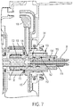
- FIG. 7 is a partial cross sectional view of a third embodiment of the transaxle of FIG. 2 showing the front support and turbine shaft adapted to provide four fluid passageways to a torque converter.
- FIG. 8 is an end view of the front support of the third embodiment.
- a group of rotatable elements are fixedly coupled to one another if they are constrained to rotate at the same speed about the same axis in all operating conditions.
- Rotatable elements may be fixedly coupled by, for example, spline connections, welding, press fitting, or machining from a common solid. Slight variations in rotational displacement between fixedly coupled elements may occur such as displacement due to lash or shaft compliance.
- two rotatable elements are selectively coupled by a shift element when the shift element constrains them to rotate at the same speed about the same axis whenever the shift element is fully engaged and the rotatable elements are free to rotate at distinct speeds in at least some other operating condition.
- a shift element that holds a rotatable element against rotation by selectively connecting it to the housing is called a brake.
- Shift elements may be actively controlled devices such as hydraulically or electrically actuated clutches or brakes or may be passive devices such as one way clutches or brakes. Two rotatable elements are coupled if they are either fixedly coupled or selectively coupled.
- FIG. 2 schematically depicts a gearbox 16 , axis transfer components 22 , and differential 26 .
- This gearing arrangement provides a variety of fixed speed ratios between turbine shaft 30 and first sprocket 32 .
- Turbine shaft 30 is driven by the torque converter 14 .
- the transaxle of FIG. 2 utilizes four simple planetary gear sets 40 , 50 , 60 , and 70 .
- a planet carrier 42 rotates about a central axis and supports a set of planet gears 44 such that the planet gears rotate with respect to the planet carrier.
- External gear teeth on the planet gears mesh with external gear teeth on a sun gear 46 and with internal gear teeth on a ring gear 48 .
- the sun gear and ring gear are supported to rotate about the same axis as the carrier.
- Gear sets 50 , 60 , and 70 are similarly structured.
- Turbine shaft 30 , first sprocket 32 , and gear sets 40 , 50 , 60 , and 70 are all supported within transaxle housing 34 .
- a suggested ratio of gear teeth for each planetary gear set is listed in Table 1.
- Sun gear 66 is fixedly coupled to turbine shaft 30 .
- Ring gear 58 and carrier 72 are fixedly coupled to first sprocket 32 .
- Ring gear 48 , carrier 62 , and ring gear 78 are mutually fixedly coupled.
- Carrier 42 is fixedly coupled to sun gear 56 .
- Carrier 52 is fixedly coupled to ring gear 68 .
- Turbine shaft 30 is selectively coupled to ring gear 48 by clutch 80 .
- Sun gear 46 is selectively coupled to turbine shaft 30 by clutch 82 and selectively held against rotation by brake 84 .
- Carrier 42 and sun gear 56 are selectively held against rotation by brake 86 .
- One way brake 88 permits carrier 52 to rotate in one direction but prevents rotation in the opposite direction.
- Brake 90 selectively holds carrier 52 against rotation in either direction.
- brake 92 selectively holds sun gear 76 against rotation.
- Chain 100 wraps around and engages first sprocket 32 and second sprocket 102 .
- Second sprocket 102 is fixedly coupled to the carrier 104 of differential 24 .
- Second sprocket 102 is approximately 2.5 times larger in diameter than first sprocket 32 . Therefore, the chain and sprocket assembly provides both the final drive ratio torque multiplication and the axis transfer functions.
- a number of beveled planet gears 106 are supported for rotation with respect to carrier 104 .
- Each planet gear meshes with both left and right beveled side gears 108 and 110 respectively.
- Left beveled side gear 108 is fixedly coupled to left half-shaft 112 while right beveled side gear 110 is fixedly coupled to right half-shaft 114 .
- Other types of differential gearing are known and may be substituted, such as a differential based on a double pinion planetary gear set with helical gears instead of bevel gears.
- FIG. 3 shows a partial cross section of a first embodiment of a transmission according to the schematic of FIG. 2 .
- Generating enough final drive ratio with a chain and sprockets requires the first sprocket 32 to be small in diameter. However, it is still important that the sprocket be properly supported.
- Turbine shaft 30 is supported by front support 120 .
- First sprocket 32 is also supported by front support 120 via bearing 122 .
- a bearing would include inner and outer races press fit into the rotating part in addition to the rolling elements themselves. These races require radial space.
- Front support 120 is machined from steel such that it is stronger and more dimensionally accurate than a cast part.
- An outer surface 124 of front support 120 is heat treated and machined to a surface finish that permits it to be the inner race for roller bearing 122 . This reduces the inner diameter of first sprocket 32 which permits reducing the pitch diameter of first sprocket 32 .
- Front support 120 is attached to intermediate member 126 which is attached, in turn, to bell housing 128 and transmission valve body 130 .
- the valve body 130 may be attached to transmission housing 34 .
- Use of intermediate member 126 minimizes the size and cost of front support 120 .
- Intermediate member 126 may be a cast part.
- Fluid is provided from the valve body to torque converter 14 through two channels in intermediate member 126 and front support 120 . Fluid flows into the torque converter through one of the channels and flows out of the torque converter through the other channel. A first portion 130 of one of these channels is formed into intermediate member 126 . A second portion 132 of the channel is formed in front support 120 . The second of the two channels is formed similarly at a different circumferential location. A hole 134 is drilled axially in turbine shaft 30 . A radial hole connects this axial hole to one of the channels in center support 120 . The other channel is connected to a gap 136 between center support 120 and turbine shaft 32 . In order to engage a torque converter lock-up clutch, the pressure difference between the two channels is reversed.
- Park gear 138 is integrally formed with sprocket 32 .
- a parking mechanism forces a parking pawl into engagement with park gear 138 , holding sprocket 32 stationary. This, in turn, holds differential carrier 104 stationary.
- FIG. 4 shows another partial cross section of the first embodiment of a transmission according to the schematic of FIG. 2 , focusing on the differential axis.
- Second sprocket 102 is fixedly coupled to differential carrier 104 by bolt 140 .
- Chain 100 continuously engages second sprocket 102 .
- FIGS. 5 and 6 show partial cross sections of a second embodiment of a transmission according to the schematic of FIG. 2 .
- park gear 138 ′ is integrally formed with second sprocket 102 rather than with first sprocket 32 .
- Placing the park gear on the differential axis offers several advantages.
- the axial length of the transmission along the main axis is reduced. Although the axial length along the differential axis may be increased relative to the first embodiment, it is still much shorter than a transmission having a final drive planetary on the differential axis.
- the chain and sprockets are not park-critical components. Failure of the chain or one of the sprockets would not allow the vehicle to roll while Park is engaged. The maximum distance that the vehicle can move with park engaged must be tightly controlled. Lash in the chain and sprocket mechanism will not contribute to this distance.
- FIGS. 7 and 8 illustrate an embodiment suitable for a transmission having a four-pass torque converter.
- control of the torque converter lock-up clutch is independent of provision of fluid to the hydrodynamic elements. Additional passageways conduct fluid to an apply chamber and a balance chamber. The fluid supplied to the balance chamber is maintained at close to ambient pressure. The pressure of the fluid supplied to the apply chamber is adjusted by the controller to set the torque capacity of the lock-up clutch. The torque capacity of the lock-up clutch is based on the pressure difference between the apply chamber and the balance chamber.
- the balance chamber is supplied with fluid leaving the hydro-dynamic chamber. The pressure of this fluid can vary in response to actions such as stroking of shifting clutches, making accurate control of lock-up clutch torque capacity more challenging.
- FIGS. 7 and 8 provides four separate fluid passageways between the valve body and the torque converter.
- front support 120 of FIGS. 3 and 5 was formed in a single piece
- the front support of FIGS. 7 and 8 is formed in two pieces: front support body 150 and front support insert 152 .
- a hollow input shaft insert 154 is installed into the input shaft to create two channels: 134 ′ on the interior of the input shaft insert and 156 between the exterior of the input shaft insert and the input shaft 30 .
- Outer surface 124 ′ of front support insert 152 is machined to serve as the inner race for bearing 122 .
- Fluid is routed to the hydrodynamic chamber via channel 158 in front support body 150 , axial channel 160 , radial channel 162 in front support insert 152 , and an axial channel between the front support and input shaft 30 .
- Fluid is returned from the hydrodynamic chamber via radial channel 164 in front support body 150 , axial channel 166 , and channel 168 in front support body 150 .
- Fluid is supplied to the lock-up clutch apply chamber via channel 132 ′ in front support body 150 , axial channel 170 , radial channel 172 in front support insert 152 , and channel 156 .
- Radial channels in input shaft 30 connect channel 172 to channel 156 and connect channel 156 to the torque converter turbine housing.
- Axial channels 160 , 166 , and 170 are formed between front support body 150 and front support insert 152 . Fluid is supplied to the lock-up clutch balance chamber via channel 174 in front support body 150 , radial channel 176 in front support insert 152 , and axial channel 134 ′ in input shaft 30 .
Landscapes
- Engineering & Computer Science (AREA)
- General Engineering & Computer Science (AREA)
- Mechanical Engineering (AREA)
- Chemical & Material Sciences (AREA)
- Combustion & Propulsion (AREA)
- Transportation (AREA)
- Transmission Devices (AREA)
- Structure Of Transmissions (AREA)
- General Details Of Gearings (AREA)
Abstract
Description
| TABLE 1 | |||
| Ring 48/ |
1.83 | ||
| |
2.257 | ||
| |
2.70 | ||
| Ring 78/ |
2.35 | ||
| TABLE 2 | |||||||||
| 80 | 82 | 84 | 86 | 90 | 92 | Ratio | Step | ||
| Rev | X | X | −4.27 | 81% | ||||
| M1 | X | X | 5.27 | |||||
| 1st | X | 5.27 | ||||||
| 2nd | X | X | 3.40 | 1.55 | ||||
| 3rd | X | X | 2.64 | 1.29 | ||||
| 4th | X | X | 2.04 | 1.29 | ||||
| 5th | X | X | 1.43 | 1.43 | ||||
| 6th | X | X | 1.00 | 1.43 | ||||
| 7th | X | X | 0.87 | 1.16 | ||||
| 8th | X | X | 0.69 | 1.25 | ||||
Claims (19)
Priority Applications (3)
| Application Number | Priority Date | Filing Date | Title |
|---|---|---|---|
| US15/372,742 US10767742B2 (en) | 2016-12-08 | 2016-12-08 | Transaxle having chain final drive |
| DE202017107363.7U DE202017107363U1 (en) | 2016-12-08 | 2017-12-04 | Transaxle unit with chain axle drive |
| CN201721694274.0U CN207740412U (en) | 2016-12-08 | 2017-12-07 | Transmission device and transmission device front supporting member |
Applications Claiming Priority (1)
| Application Number | Priority Date | Filing Date | Title |
|---|---|---|---|
| US15/372,742 US10767742B2 (en) | 2016-12-08 | 2016-12-08 | Transaxle having chain final drive |
Publications (2)
| Publication Number | Publication Date |
|---|---|
| US20180163835A1 US20180163835A1 (en) | 2018-06-14 |
| US10767742B2 true US10767742B2 (en) | 2020-09-08 |
Family
ID=61525773
Family Applications (1)
| Application Number | Title | Priority Date | Filing Date |
|---|---|---|---|
| US15/372,742 Expired - Fee Related US10767742B2 (en) | 2016-12-08 | 2016-12-08 | Transaxle having chain final drive |
Country Status (3)
| Country | Link |
|---|---|
| US (1) | US10767742B2 (en) |
| CN (1) | CN207740412U (en) |
| DE (1) | DE202017107363U1 (en) |
Cited By (1)
| Publication number | Priority date | Publication date | Assignee | Title |
|---|---|---|---|---|
| KR20210056918A (en) * | 2019-11-08 | 2021-05-20 | 티비아이 모션 테크놀로지 컴퍼니 리미티드 | Linear motion system |
Families Citing this family (8)
| Publication number | Priority date | Publication date | Assignee | Title |
|---|---|---|---|---|
| US10253850B2 (en) | 2016-09-28 | 2019-04-09 | Allison Transmission, Inc. | Multi-speed planetary transmission |
| US10473190B2 (en) | 2016-09-28 | 2019-11-12 | Allison Transmission, Inc. | Multi-speed planetary transmission |
| US10364867B2 (en) | 2016-09-28 | 2019-07-30 | Allison Transmission, Inc. | Multi-speed planetary transmission |
| US10302173B2 (en) * | 2016-09-28 | 2019-05-28 | Allison Transmission, Inc. | Multi-speed planetary transmission |
| US10060512B2 (en) | 2016-09-28 | 2018-08-28 | Allison Transmission, Inc. | Multi-speed planetary transmission |
| US20190136959A1 (en) * | 2017-11-09 | 2019-05-09 | GM Global Technology Operations LLC | Locking bearing assembly |
| DE102020204411A1 (en) | 2020-04-06 | 2021-10-07 | Robert Bosch Gesellschaft mit beschränkter Haftung | Axle differential |
| US11708903B1 (en) * | 2022-10-20 | 2023-07-25 | Borgwarner, Inc. | Park system integration with chain drive |
Citations (13)
| Publication number | Priority date | Publication date | Assignee | Title |
|---|---|---|---|---|
| US3986413A (en) * | 1975-07-03 | 1976-10-19 | Ford Motor Company | Four-speed automatic coupling transmission |
| US6155364A (en) | 1996-02-21 | 2000-12-05 | Toyota Jidosha Kabushiki Kaisha | Hybrid drive system wherein planetary gear mechanism is disposed radially inwardly of stator coil of motor/generator |
| US6354974B1 (en) | 1999-04-26 | 2002-03-12 | Luk Lamellen Und Kupplungsbau Gmbh | Power train for use in motor vehicles and the like |
| US20090011892A1 (en) * | 2007-07-05 | 2009-01-08 | Aisin Aw Co., Ltd. | Automatic transmission |
| US7841960B2 (en) | 2008-03-18 | 2010-11-30 | Ford Global Technologies | Eight speed planetary kinematic arrangement with two rotating clutches |
| US20110098151A1 (en) | 2008-06-12 | 2011-04-28 | Zf Friedrichshafen Ag | Hybrid drive train for a motor vehicle and method for operating the hybrid drive train |
| US8491432B2 (en) | 2009-06-23 | 2013-07-23 | Fisker Automotive, Inc. | Drive configurations for high speed motor drive systems |
| US8517882B2 (en) * | 2007-11-20 | 2013-08-27 | Magna Powertrain Usa, Inc. | Two-speed transaxle gearbox for electric vehicles |
| US8562476B2 (en) * | 2008-05-16 | 2013-10-22 | Borgwarner Inc. | Manual transmission using chain and planetary gear set as final drive |
| WO2015097510A1 (en) | 2013-12-26 | 2015-07-02 | Toyota Jidosha Kabushiki Kaisha | Drive device for hybrid vehicle |
| US9175759B2 (en) | 2011-11-04 | 2015-11-03 | Aisin Aw Co., Ltd. | Vehicle drive device |
| US20160193908A1 (en) | 2013-09-13 | 2016-07-07 | Toyota Jidosha Kabushiki Kaisha | Power transmitting apparatus for hybrid vehicle |
| US20170130812A1 (en) * | 2015-11-10 | 2017-05-11 | Ford Global Technologies, Llc | Four pass torque converter |
Family Cites Families (1)
| Publication number | Priority date | Publication date | Assignee | Title |
|---|---|---|---|---|
| US7601270B1 (en) * | 1999-06-28 | 2009-10-13 | California Institute Of Technology | Microfabricated elastomeric valve and pump systems |
-
2016
- 2016-12-08 US US15/372,742 patent/US10767742B2/en not_active Expired - Fee Related
-
2017
- 2017-12-04 DE DE202017107363.7U patent/DE202017107363U1/en not_active Expired - Lifetime
- 2017-12-07 CN CN201721694274.0U patent/CN207740412U/en not_active Expired - Fee Related
Patent Citations (13)
| Publication number | Priority date | Publication date | Assignee | Title |
|---|---|---|---|---|
| US3986413A (en) * | 1975-07-03 | 1976-10-19 | Ford Motor Company | Four-speed automatic coupling transmission |
| US6155364A (en) | 1996-02-21 | 2000-12-05 | Toyota Jidosha Kabushiki Kaisha | Hybrid drive system wherein planetary gear mechanism is disposed radially inwardly of stator coil of motor/generator |
| US6354974B1 (en) | 1999-04-26 | 2002-03-12 | Luk Lamellen Und Kupplungsbau Gmbh | Power train for use in motor vehicles and the like |
| US20090011892A1 (en) * | 2007-07-05 | 2009-01-08 | Aisin Aw Co., Ltd. | Automatic transmission |
| US8517882B2 (en) * | 2007-11-20 | 2013-08-27 | Magna Powertrain Usa, Inc. | Two-speed transaxle gearbox for electric vehicles |
| US7841960B2 (en) | 2008-03-18 | 2010-11-30 | Ford Global Technologies | Eight speed planetary kinematic arrangement with two rotating clutches |
| US8562476B2 (en) * | 2008-05-16 | 2013-10-22 | Borgwarner Inc. | Manual transmission using chain and planetary gear set as final drive |
| US20110098151A1 (en) | 2008-06-12 | 2011-04-28 | Zf Friedrichshafen Ag | Hybrid drive train for a motor vehicle and method for operating the hybrid drive train |
| US8491432B2 (en) | 2009-06-23 | 2013-07-23 | Fisker Automotive, Inc. | Drive configurations for high speed motor drive systems |
| US9175759B2 (en) | 2011-11-04 | 2015-11-03 | Aisin Aw Co., Ltd. | Vehicle drive device |
| US20160193908A1 (en) | 2013-09-13 | 2016-07-07 | Toyota Jidosha Kabushiki Kaisha | Power transmitting apparatus for hybrid vehicle |
| WO2015097510A1 (en) | 2013-12-26 | 2015-07-02 | Toyota Jidosha Kabushiki Kaisha | Drive device for hybrid vehicle |
| US20170130812A1 (en) * | 2015-11-10 | 2017-05-11 | Ford Global Technologies, Llc | Four pass torque converter |
Cited By (2)
| Publication number | Priority date | Publication date | Assignee | Title |
|---|---|---|---|---|
| KR20210056918A (en) * | 2019-11-08 | 2021-05-20 | 티비아이 모션 테크놀로지 컴퍼니 리미티드 | Linear motion system |
| KR102408686B1 (en) | 2019-11-08 | 2022-06-13 | 티비아이 모션 테크놀로지 컴퍼니 리미티드 | Linear motion system |
Also Published As
| Publication number | Publication date |
|---|---|
| US20180163835A1 (en) | 2018-06-14 |
| CN207740412U (en) | 2018-08-17 |
| DE202017107363U1 (en) | 2018-01-15 |
Similar Documents
| Publication | Publication Date | Title |
|---|---|---|
| US10767742B2 (en) | Transaxle having chain final drive | |
| US8968144B2 (en) | Multi-speed transmission | |
| EP1533543B1 (en) | Power transmission mechanism | |
| US9222550B2 (en) | Multi-speed transmission | |
| US9175748B2 (en) | Multi-speed transmission | |
| US7914413B2 (en) | Automatic transmission | |
| KR101003941B1 (en) | Automatic transmission | |
| US4148229A (en) | Overdrive device for automatic transmission | |
| US8702553B2 (en) | Transfer shaft support | |
| CN107013634B (en) | Multi-speed transmission | |
| CN207470708U (en) | Speed changer | |
| US20150018156A1 (en) | Multi-speed transmission | |
| JP3584448B2 (en) | Automatic transmission | |
| US10801588B2 (en) | Multi-speed transmission | |
| US8454468B2 (en) | Clutch piston support | |
| US9638291B2 (en) | Multi-speed transmission | |
| US8844695B2 (en) | Carrying fluid to balance dams in a servo piston support | |
| US8641574B2 (en) | Transfer shaft support | |
| US10344830B2 (en) | Multi-speed transmission | |
| US20120220405A1 (en) | Front Support for Transmission Gear Box | |
| US8403798B2 (en) | Final drive mechanism for a transmission | |
| US9964183B2 (en) | Transmission with high speed clutch hub | |
| CN101263323B (en) | Automotive transmission | |
| US8544628B2 (en) | Pressure and flow continuity through transmission supports | |
| EP2980450A1 (en) | Automatic transmission for vehicles |
Legal Events
| Date | Code | Title | Description |
|---|---|---|---|
| AS | Assignment |
Owner name: FORD GLOBAL TECHNOLOGIES, LLC, MICHIGAN Free format text: ASSIGNMENT OF ASSIGNORS INTEREST;ASSIGNORS:JANSON, DAVID ALLEN;GOLESKI, GREGORY DANIEL;OH, DAVID GON;REEL/FRAME:040601/0825 Effective date: 20161206 |
|
| STPP | Information on status: patent application and granting procedure in general |
Free format text: DOCKETED NEW CASE - READY FOR EXAMINATION |
|
| STPP | Information on status: patent application and granting procedure in general |
Free format text: NON FINAL ACTION MAILED |
|
| STPP | Information on status: patent application and granting procedure in general |
Free format text: RESPONSE TO NON-FINAL OFFICE ACTION ENTERED AND FORWARDED TO EXAMINER |
|
| STPP | Information on status: patent application and granting procedure in general |
Free format text: NON FINAL ACTION MAILED |
|
| STPP | Information on status: patent application and granting procedure in general |
Free format text: RESPONSE TO NON-FINAL OFFICE ACTION ENTERED AND FORWARDED TO EXAMINER |
|
| ZAAA | Notice of allowance and fees due |
Free format text: ORIGINAL CODE: NOA |
|
| ZAAB | Notice of allowance mailed |
Free format text: ORIGINAL CODE: MN/=. |
|
| STCF | Information on status: patent grant |
Free format text: PATENTED CASE |
|
| FEPP | Fee payment procedure |
Free format text: MAINTENANCE FEE REMINDER MAILED (ORIGINAL EVENT CODE: REM.); ENTITY STATUS OF PATENT OWNER: LARGE ENTITY |
|
| LAPS | Lapse for failure to pay maintenance fees |
Free format text: PATENT EXPIRED FOR FAILURE TO PAY MAINTENANCE FEES (ORIGINAL EVENT CODE: EXP.); ENTITY STATUS OF PATENT OWNER: LARGE ENTITY |
|
| STCH | Information on status: patent discontinuation |
Free format text: PATENT EXPIRED DUE TO NONPAYMENT OF MAINTENANCE FEES UNDER 37 CFR 1.362 |
|
| FP | Lapsed due to failure to pay maintenance fee |
Effective date: 20240908 |