US10766176B2 - Injection-molding systems having hot-runner manifolds containing non-melt internal channels for providing operability enhancements - Google Patents
Injection-molding systems having hot-runner manifolds containing non-melt internal channels for providing operability enhancements Download PDFInfo
- Publication number
- US10766176B2 US10766176B2 US14/905,981 US201414905981A US10766176B2 US 10766176 B2 US10766176 B2 US 10766176B2 US 201414905981 A US201414905981 A US 201414905981A US 10766176 B2 US10766176 B2 US 10766176B2
- Authority
- US
- United States
- Prior art keywords
- injection
- hot
- fluid
- nozzle
- melt
- Prior art date
- Legal status (The legal status is an assumption and is not a legal conclusion. Google has not performed a legal analysis and makes no representation as to the accuracy of the status listed.)
- Active, expires
Links
Images


Classifications
-
- B—PERFORMING OPERATIONS; TRANSPORTING
- B29—WORKING OF PLASTICS; WORKING OF SUBSTANCES IN A PLASTIC STATE IN GENERAL
- B29C—SHAPING OR JOINING OF PLASTICS; SHAPING OF MATERIAL IN A PLASTIC STATE, NOT OTHERWISE PROVIDED FOR; AFTER-TREATMENT OF THE SHAPED PRODUCTS, e.g. REPAIRING
- B29C45/00—Injection moulding, i.e. forcing the required volume of moulding material through a nozzle into a closed mould; Apparatus therefor
- B29C45/17—Component parts, details or accessories; Auxiliary operations
- B29C45/26—Moulds
- B29C45/27—Sprue channels ; Runner channels or runner nozzles
- B29C45/2737—Heating or cooling means therefor
- B29C45/2738—Heating or cooling means therefor specially adapted for manifolds
-
- B—PERFORMING OPERATIONS; TRANSPORTING
- B29—WORKING OF PLASTICS; WORKING OF SUBSTANCES IN A PLASTIC STATE IN GENERAL
- B29C—SHAPING OR JOINING OF PLASTICS; SHAPING OF MATERIAL IN A PLASTIC STATE, NOT OTHERWISE PROVIDED FOR; AFTER-TREATMENT OF THE SHAPED PRODUCTS, e.g. REPAIRING
- B29C45/00—Injection moulding, i.e. forcing the required volume of moulding material through a nozzle into a closed mould; Apparatus therefor
- B29C45/17—Component parts, details or accessories; Auxiliary operations
- B29C45/26—Moulds
- B29C45/27—Sprue channels ; Runner channels or runner nozzles
- B29C45/2725—Manifolds
-
- B—PERFORMING OPERATIONS; TRANSPORTING
- B29—WORKING OF PLASTICS; WORKING OF SUBSTANCES IN A PLASTIC STATE IN GENERAL
- B29C—SHAPING OR JOINING OF PLASTICS; SHAPING OF MATERIAL IN A PLASTIC STATE, NOT OTHERWISE PROVIDED FOR; AFTER-TREATMENT OF THE SHAPED PRODUCTS, e.g. REPAIRING
- B29C45/00—Injection moulding, i.e. forcing the required volume of moulding material through a nozzle into a closed mould; Apparatus therefor
- B29C45/17—Component parts, details or accessories; Auxiliary operations
- B29C45/26—Moulds
- B29C45/27—Sprue channels ; Runner channels or runner nozzles
- B29C45/2737—Heating or cooling means therefor
- B29C2045/2754—Plurality of independent heating or cooling means, e.g. independently controlling the heating of several zones of the nozzle
-
- B—PERFORMING OPERATIONS; TRANSPORTING
- B29—WORKING OF PLASTICS; WORKING OF SUBSTANCES IN A PLASTIC STATE IN GENERAL
- B29C—SHAPING OR JOINING OF PLASTICS; SHAPING OF MATERIAL IN A PLASTIC STATE, NOT OTHERWISE PROVIDED FOR; AFTER-TREATMENT OF THE SHAPED PRODUCTS, e.g. REPAIRING
- B29C45/00—Injection moulding, i.e. forcing the required volume of moulding material through a nozzle into a closed mould; Apparatus therefor
- B29C45/17—Component parts, details or accessories; Auxiliary operations
- B29C45/26—Moulds
- B29C45/27—Sprue channels ; Runner channels or runner nozzles
- B29C45/28—Closure devices therefor
- B29C45/2806—Closure devices therefor consisting of needle valve systems
- B29C45/281—Drive means therefor
- B29C2045/2827—Needle valves driven by an annular piston mounted around the nozzle
Definitions
- the present invention generally relates to the field of injection molding.
- the present invention is directed to injection-molding systems having hot-runner manifolds containing non-melt internal channels for providing operability enhancements.
- An injection-molding manifold distributes one or more molten materials, or one or more “melts,” such as one or more plastics, from an injection-molding machine to injection-molding nozzles via a network of melt-channels within the manifold.
- Each melt is intermittently delivered to one or more mold cavities via the injection-molding nozzles during molding operations.
- the melt in each melt-channel is typically heated using electrical heaters located on the exterior of the manifold. If the nozzles are of a valve-gated type, actuators that reside on the side of the manifold opposite the nozzles are typically used. Sometimes equipment operators disengage and reengage the nozzles with a mold plate/gate inserts while the nozzles are still hot. This is known as “hot latching” and can lead to excessive wear and damage to the nozzles and/or mold plate/gate inserts where the components engage one another.
- the present disclosure is directed to an injection-molding system.
- the system includes a hot-runner manifold comprising a body that includes a melt-inlet, an injection-nozzle region, a melt channel extending from the melt inlet to the injection-nozzle region, a non-melt-fluid inlet, a non-melt-fluid outlet, and a non-melt fluid channel extending from the non-melt-fluid inlet to the non-melt-fluid outlet and being fluidly isolated from the melt channel.
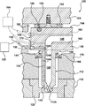
- FIG. 1 is a cross-sectional partial view of an injection-molding apparatus that includes a hot-runner manifold containing non-melt channels for nozzle cooling;
- FIG. 2 is a cross-sectional partial view of an injection-molding apparatus similar to the injection-molding apparatus of FIG. 1 , wherein the nozzles are monolithically formed with the hot-runner manifold;
- FIG. 3 is a cross-sectional partial view of an injection-molding apparatus that includes a hot-runner manifold containing non-melt channels for providing an actuating fluid to nozzle-side valve actuators;
- FIG. 4 is a cross-sectional partial view of an injection-molding apparatus similar to the injection-molding apparatus of FIG. 3 , wherein the nozzles are monolithically formed with the hot-runner manifold;
- FIG. 5 is top view of a hot-runner manifold that includes integrated non-melt channels that circulate a heating fluid for maintaining melt in the melt channels at a desired temperature.
- An aspect of the present invention is the providing of one or more types of non-melt channels to a hot-runner manifold of an injection-molding apparatus to any one or more of a variety of functionalities to the injection-molding apparatus.
- Such functionalities include, but are not limited to, providing a cooling fluid (e.g., air) to tips of injection nozzles, providing an actuating fluid, (e.g., air or liquid) to injection valves, and providing a heating fluid (e.g., a high-temperature alkylated aromatic compound, oil, etc.) for maintaining the temperature of melt in the melt channels within the hot-runner manifold.
- non-melt channels can be provided in any manner, such as via conventional machining processes and conventional casting processes, as well as additive manufacturing processes, among others.
- injection-molding apparatus components such as hot-runner manifolds and nozzles, made using one or more additive manufacturing processes can be “finely tuned” in terms of material usage and optimization and configuration optimization so as to produce highly effective and efficient components.
- this fine tuning also extends to the functionalities and features provided by the non-melt channels described herein. That said, similar non-melt channels can also be executed with conventional manufacturing processes with commensurate success.
- FIG. 1 illustrates an injection-molding apparatus 100 made in accordance with aspects of the present invention.
- Injection-molding apparatus 100 includes a hot-runner assembly 104 that includes a manifold 108 and a plurality of hot-tip type nozzles, one of which is shown as hot-tip nozzle 112 .
- a practice among some injection molders is to perform a “hot-latching” procedure in which a mold, here mold 116 , is disengaged from a hot-runner assembly, here assembly 104 , while apparatus 100 is still hot.
- tip 112 A of nozzle 112 is still hot and, therefore, is typically thermally expanded into firm engagement with the mold, here with a gate insert 120 of mold 116 .
- the firm engagement of tip 112 A with gate insert 120 can result in severe wear of one or both parts or even damage to one or both parts.
- injection-molding apparatus 100 for allowing an operator to cool each nozzle tip, here, tip 112 A, by providing an integral non-melt coolant channel 124 , which in the embodiment shown, has, in conjunction with nozzle 112 , a segment 124 A formed in hot-runner manifold 108 and a segment 124 B formed in nozzle 112 .
- Coolant channel 124 can receive a coolant, such as air, from a coolant source 128 (e.g., an air compressor) via any suitable means, such as a fitting, here a hose 132 having a quick-connect fitting 136 designed and configured to be quickly engaged with hot-runner manifold 108 when the operator (not shown) desires to perform a hot-latching procedure.
- a coolant source 128 e.g., an air compressor
- any suitable means such as a fitting, here a hose 132 having a quick-connect fitting 136 designed and configured to be quickly engaged with hot-runner manifold 108 when the operator (not shown) desires to perform a hot-latching procedure.
- quick-connect fitting 136 eliminates the need for coolant source 128 to be connected to hot-runner manifold 108 during molding operations. That said, any suitable connection can be made between coolant source 128 and hot-runner manifold 108 , including a connection that remains connected during molding operations other than hot-latching.
- hose 132 and quick-connect fitting 136 can serve all hot-tip nozzles (only one nozzle 112 shown for convenience) on hot-runner manifold 108 .
- a segment 124 C of coolant channel 124 within hot-runner manifold 108 can provide coolant to any one or more of the other hot-tip nozzles that are not illustrated but that are off to the right relative to FIG. 1 .
- hot-tip nozzle 112 is formed separately from hot-runner manifold 108 , and each of the nozzle and manifold can be made using any suitable techniques.
- segments 124 A to 124 C of coolant channel 124 can be drilled.
- segments 124 A to 124 C of coolant channel 124 can be formed as part of a casting process or an additive manufacturing process, a/k/a a freeform fabrication process.
- An important aspect of providing cooling for nozzle tip 112 A is to deliver coolant to a location proximate to the nozzle tip.
- FIG. 1 illustrates one location of an outlet 140 for coolant channel 124 .
- hot-tip nozzle 112 is formed separately from hot-runner manifold 108 in this example, provisions may need to be made to ensure proper alignment of segments 124 A and 124 B of coolant channel 124 at interface 144 at operating temperatures. Because similar alignment issues are often encountered in the design and execution of conventional hot-runner assemblies, those skilled in the art will readily be able to configure hot-tip nozzle 112 and hot-runner manifold 108 to ensure such alignment.
- Hot-runner manifold 108 and hot-tip nozzles 112 include melt channels 148 that carry a melt (not shown), such as a plastic melt, from an injection machine (not shown) to mold 116 during injection molding operations.
- melt channels 148 extend from one or more inlets that receive the melt from the injection machine to hot-tip nozzles 112 .
- Each inlet is formed in hot-runner manifold 108 and may receive the melt from a sprue bushing or other structure that interfaces with the injection machine.
- Each hot-tip nozzle 112 is located at a nozzle region 150 of hot-runner manifold 108 .
- hot-runner manifold 108 is a unitary monolithic body that can be readily fabricated using a suitable fabrication technique, such as a freeform fabrication technique (see below). That said, hot-runner manifold 108 may be made using conventional manifold fabrication techniques, such as straight drilling and plugging, as long as the configurations of the various channels within the manifold are not too complex/intricate.
- melt in the melt channels is kept hot using electrical-resistance-type heating elements, such as heating element 152 of FIG. 1 , which is often installed into a recess, here recess 156 , formed in the backside of hot-runner manifold 108 .
- electrical-resistance-type heating elements such as heating element 152 of FIG. 1
- recess 156 formed in the backside of hot-runner manifold 108 .
- a problem that can be experienced with using conventional electrical-resistance-type heating elements of this type is that relatively high heat must be applied by the heating elements because the melt channels are relatively far from the melt channels, and this high heat can cause localized overheating if the heating elements are poorly routed.
- hot-runner manifold 108 optionally includes non-melt heating channels 160 provided to carry a suitable heating fluid, such as a high-temperature alkylated aromatic compound, oil, etc., from a heating-fluid source 164 into the manifold in close proximity to melt channels 148 .
- a suitable heating fluid such as a high-temperature alkylated aromatic compound, oil, etc.
- a benefit of running heating channels 160 close to melt channels 148 is that the temperature of the heating fluid can be kept low relative to the temperature needed in conventional electrical-resistance-type heating elements, such as heating element 152 .
- heating channels 160 are arranged to form a continuous circuit between a fluid inlet 168 , which receives the heating fluid from the heating-fluid source 164 , and a fluid outlet 172 , from which the heating fluid is returned to the heating source for reheating and recirculation.
- heating channels 160 are shown as being straight, such that they can be formed using any suitable manufacturing technique, including drilling and plugging, casting, and additive manufacturing.
- the heating channels can be configured and arranged in virtually any suitable/desired configuration and arrangement to suit a particular design.
- Other examples of heating channels of the present disclosure are illustrated in connection with other figures of this disclosure.
- a single manifold can have a plurality of separate circuits that can be served by either a plurality of fluid inlets and outlets (like inlet 168 and outlet 172 ) or inlet and outlet manifolds (not shown) or a combination of both.
- injection-molding apparatus 100 of FIG. 1 includes a mold plate 176 that defines a manifold cavity 180 in which hot-runner manifold 108 is located.
- a backing plate 184 is provided to close mold cavity 180 , as well as to hold hot-runner manifold 108 and hot-tip nozzle 112 in place via an arrangement that includes a Bellville washer 188 and insulative spacer 192 , among other components.
- FIG. 2 illustrates an embodiment of an injection-molding apparatus 200 that is similar to injection-molding apparatus 100 of FIG. 1 , except for a few differences, including the fact that in apparatus 200 of FIG. 2 , each hot-tip nozzle 204 (one shown) is formed monolithically with the hot-runner manifold 208 , such as by using an additive manufacturing process, for example, a freeform-fabrication process, some of which are described below in connection with FIG. 5 . Another difference is the path of each non-melt nozzle-tip-coolant channel 212 , which unlike the path of coolant channel 124 of FIG. 1 , cannot be formed using conventional straight drilling and plugging techniques.
- the relatively large-radiused bend 212 A of coolant channel 212 needs to be formed using another process, such as an additive-manufacturing process, for example, a freeform-fabrication process.
- a further difference is the arrangement (i.e., path) of the non-melt heating-fluid channels 216 .
- heating-fluid channels 216 of FIG. 2 are arranged to run in an up-and-down (relative to FIG. 2 ) zig-zag path generally on both “sides” (front and back relative to FIG. 2 ) of the melt channel 220 .
- Such an arrangement of heating-fluid channels 216 is suited for manufacturing using freeform-fabrication techniques.
- heating-fluid channels 216 are present only in hot-runner manifold 208 in the manner of heating-fluid channels 160 of FIG. 1 , in injection-molding apparatus 200 of FIG. 2 , heating-fluid channels 216 extend into hot-tip nozzles 204 .
- this eliminates the need for conventional external heating elements (not shown) that are typically electrical-resistance-type heating elements present around each nozzle.
- hot-tip nozzles 204 are monolithically formed with hot-runner manifold 208 can make it relatively easy to run heating fluid channels into the nozzles free of any part-to-part interruptions, such as nozzle-to-manifold interface 144 of FIG. 1
- the heating-fluid channels can likewise be run into the nozzles from the manifold in a manner similar to heating-fluid channels 216 of FIG. 2 .
- care must be taken to ensure that the nozzle-to-manifold interfaces, such as interface 144 of FIG. 1 , is fluid tight in the regions wherein the heating-fluid channels cross those interfaces.
- Suitable fluid-tight seals can be made, for example, using gaskets and/or sealing rings, or a precisely machined pre-loaded interface (such as the one shown in FIG. 1 ), among other things.
- Other components and aspects of injection-molding apparatus 200 of FIG. 2 can be the same as or similar to the like components and aspects of injection-molding apparatus 100 of FIG. 1 .
- FIG. 3 illustrates another use of non-melt channels within a hot-runner manifold, nozzle, and/or other components.
- this figures shows an injection molding apparatus 300 that includes a hot-runner manifold 302 and a nozzle/valve assembly 304 that comprises a valve-gated nozzle 306 and a valve 308 .
- Valve-gated nozzle 306 includes a main body 310 composed of two parts 310 A and 310 B, with part 310 B including a nozzle tip 310 C.
- Nozzle parts 310 A and 310 B contain, respectively, melt-channel segments 312 A and 312 B of a melt channel 312 that carry a melt (not shown) from a melt channel 314 within hot-runner manifold 302 to nozzle tip 310 C.
- Valve 308 includes a valve pin 316 slidably engaged within a receiving passageway 318 within nozzle part 312 B.
- Valve pin 316 is designed and configured to be movable to a closed position (not shown) wherein it sealingly engages a nozzle-tip outlet 320 to controllably stop the flow of the melt from melt-channel segment 312 B.
- valve pin 316 is shown in an open position, wherein the melt in melt-channel segment 312 B can flow through nozzle-tip outlet 320 , through a gate insert 322 , and into a mold cavity 324 within the mold 326 .
- Valve 308 also includes a piston 328 having a collar 330 and a valve-pin support 332 .
- Piston collar 330 is designed and configured to reciprocate within a cavity 334 defined by a nozzle sleeve 336 on the inside and a wall 338 of the mold plate 340 on the inside.
- a first pair of piston rings 342 A and 342 B provide a sliding seal between piston collar 330 and nozzle sleeve 336
- a second pair of piston rings 344 A and 344 B provide a sliding seal between the piston collar and wall 338 of mold plate 340 .
- piston rings 342 A and 344 A cooperate with their respective interfacing parts to form a first actuation chamber 346
- piston rings 342 B and 344 B cooperate with their respective interfacing parts to form a second actuation chamber 348
- Valve-pin support 332 fixedly holds valve pin 316 via a retainer 350 and a fastener 352 .
- first and second actuation chambers 346 and 348 are alternatingly pressurized (or evacuated or one is pressurized and the other is evacuated) to cause piston collar 330 and, therefore, valve pin 316 to move up and down (relative to FIG. 3 ).
- valve pin 316 is alternatingly moved between open and closed positions using one or more actuation fluids (not shown), such as air, hydraulic fluid, etc., in conjunction with first and second actuation chambers 346 and 348 .
- injection-molding apparatus 300 includes, respectively, first and second non-melt actuation-fluid channels 354 and 356 .
- First and second non-melt actuation-fluid channels 354 and 356 are fluidly coupled to one or more actuation-fluid controllers 358 that perform the necessary actuation-fluid pressurization and/or evacuation needed to actuate valve 308 .
- first non-melt actuation-fluid channel 354 extends through hot-runner manifold 308 , nozzle part 310 A, and nozzle sleeve 336 via channel segments 354 A, 354 B, and 354 C, respectively
- second non-melt actuation-fluid channel 356 extends through the hot runner manifold, nozzle part 310 A, and the nozzle sleeve via channel segments 356 A, 356 B, and 356 C, respectively.
- Each of actuation-fluid channels 354 and 356 can be provided with any suitable coupling ports (only one port 360 shown), respectively, for coupling to the one or more actuation-fluid controllers 354 .
- Sealing of the various channel segments 354 A- 354 C and 356 A- 356 C can be effected using any suitable means, such as using gaskets and/or sealing/rings or a precisely machined pre-loaded interface (such as the interface 362 shown in FIG. 3 ), among other things.
- injection-molding apparatus 300 includes a heating-fluid channel 364 , which, as described above in connection with FIGS. 1 and 2 , is provided for the purpose of keeping the melt within hot-runner manifold 308 , here the melt within melt channel segment 312 C within the manifold.
- heating-fluid channel 364 can have any suitable arrangement and configuration, and the configuration and arrangement shown in FIG. 3 is merely exemplary and should in no way be considered limiting.
- heating-fluid channel 364 or plurality of channels can have any configuration and arrangement that performs the function of keeping the melt within hot-runner manifold 308 at the proper temperature.
- heating-fluid channel 364 and associated components can be the same as or similar to the like aspects and components described above in connection with FIGS. 1 and 2 .
- other components and aspects of injection-molding apparatus 300 of FIG. 3 can be the same as or similar to the like components and aspects of injection-molding apparatus 100 of FIG. 1 .
- FIG. 4 illustrates an embodiment of an injection-molding apparatus 400 that is similar to injection-molding apparatus 300 of FIG. 3 , except for a few differences, including the fact that in apparatus 400 of FIG. 4 , main body 404 of each valve-gated nozzle 408 (one shown) is formed monolithically with the hot-runner manifold 412 , such as by using an additive manufacturing process, for example, a freeform-fabrication process. Another difference is the paths of the non-melt actuation-fluid channels 416 and 420 , which unlike the paths of actuation-fluid channels 354 and 356 of FIG. 3 , cannot be formed using conventional straight-line drilling and plugging techniques.
- the relatively large-radiused bends 416 A and 420 A of actuation-fluid channels 416 and 420 need to be formed using another process, such as an additive-manufacturing process, for example, a freeform-fabrication process.
- a further difference is the arrangement (i.e., path) of the non-melt heating-fluid channels 424 .
- heating-fluid channels 424 of FIG. 4 are arranged to run in an up-and-down (relative to FIG. 4 ) zig-zag path generally on both “sides” (front and back relative to FIG. 4 ) of the melt channel 428 .
- Such an arrangement of heating-fluid channel 424 is suited for manufacturing using freeform-fabrication techniques.
- heating-fluid channels 424 are present only in hot-runner manifold 412 in the manner of heating-fluid channels 364 of FIG. 3 , in injection-molding apparatus 400 of FIG. 4 , heating-fluid channels 424 extend into valve-gated nozzles 408 .
- this eliminates the need for conventional external heating elements (not shown) that are typically electrical-resistance-type heating elements present around each nozzle.
- valve-gated nozzles 408 is monolithically formed with hot-runner manifold 412 can make it relatively easy to run heating fluid channels into the nozzles free of any part-to-part interruptions, such as nozzle-to-manifold interface 362 of FIG. 3
- the heating-fluid channels can likewise be run into the nozzles from the manifold in a manner similar to heating-fluid channels 424 of FIG. 4 .
- care must be taken to ensure that each nozzle-to-manifold interface, such as interface 362 of FIG. 3 , is fluid tight in the regions wherein the heating-fluid channels cross the interface.
- Suitable fluid-tight seals can be made, for example, using gaskets and/or sealing/rings), or a precisely machined pre-loaded interface (such as the one shown in FIG. 3 ), among other things.
- Other components and aspects of injection-molding apparatus 400 of FIG. 4 can be the same as or similar to the like components and aspects of injection-molding apparatus 100 of FIG. 1 .
- FIG. 5 illustrates a relatively complexly shaped hot-runner manifold 500 that is formed using a freeform fabrication process, which allows for such complexity, complexity that is not possible with conventional hot-runner manifold fabricating processes.
- Hot-runner manifold 500 includes sixteen nozzles 504 ( 1 ) to 504 ( 16 ), each fed with melt (not shown) by a corresponding melt-channel 508 ( 1 ) to 508 ( 16 ).
- melt-channels 508 ( 1 ) to 508 ( 16 ) are particularly configured to equalize the pressure drops from inlets 512 (only a few of which are labeled to avoid clutter) to nozzles 504 ( 1 ) to 504 ( 16 ) among all of the melt channels so that, during injection of the melt into a mold (not shown) the pressures at the outlets of the nozzles are all the same or substantially the same as one another. This allows for very predictable and uniform flow of melt from the injection machine (not shown) to the mold.
- This pressure-drop equalization is effected in the embodiment shown by adjusting the lengths and/or pathways of the ones of melt channels 508 ( 1 ) to 508 ( 16 ) that feed nozzles 504 ( 2 ) to 504 ( 7 ) and 504 ( 10 ) to 504 ( 15 ), i.e., the ones of nozzles 504 ( 1 ) to 504 ( 16 ) that are closer than nozzles 504 ( 1 ), 504 ( 8 ), 504 ( 9 ), and 504 ( 16 ) that are farthest from their corresponding respective inlets 512 so that they have the same pressure drop as the naturally longest melt channels 508 ( 1 ), 508 ( 8 ), 508 ( 9 ), and 508 ( 16 ) that feed those farthest nozzles 504 ( 1 ), 504 ( 8 ), 504 ( 9 ), and 504 ( 16 ).
- melt channels 508 ( 2 ) to 508 ( 7 ) and 508 ( 10 ) to 508 ( 15 ) are longer and less direct in routing than they would need to be if they were largely straight like melt-channels 508 ( 1 ), 508 ( 9 ), 508 ( 10 ), and 508 ( 16 ).
- melt channels 508 ( 2 ) to 508 ( 7 ) and 508 ( 10 ) to 508 ( 15 ) which are formed in an otherwise unitary monolithic body 516 , are only practicable using freeform fabrication techniques.
- melt channels 508 ( 2 ) to 508 ( 7 ) and 508 ( 10 ) to 508 ( 15 ) simply cannot be made using conventional hot-runner manifold fabrication techniques, such as straight drilling, plugging, and machining.
- Hot-runner manifold 500 further includes a set of complexly shaped non-melt channels that are in the form of heating channels 520 ( 1 ) to 520 ( 16 ) that, like melt channels 508 ( 1 ) to 508 ( 16 ) are formed in unitary monolithic body 516 by virtue of the selected freeform fabrication process.
- an effective and efficient way to implement heating channels is to locate them as close to the melt channels as practicable so as to place the heat as close to the melt channels as possible.
- heating channels 520 ( 1 ) to 520 ( 16 ) are configured as helixes (only four helixes 524 ( 1 ) to 524 ( 4 ) shown to avoid clutter), each “corkscrewing” around a corresponding one of the melt channels.
- all of heating channels 520 ( 1 ) to 520 ( 16 ) share a common inlet 528
- heating channels 520 ( 1 ) to 520 ( 4 ) and 520 ( 13 ) to 520 ( 16 ) share a common outlet 532 ( 1 )
- heating channels 520 ( 5 ) to 520 ( 12 ) share a common outlet 532 ( 2 ).
- the configuration(s) of the heating channel(s) may be different from the configurations of heating channels 520 ( 1 ) to 520 ( 16 ) and the number of inlets and outlets for the heating channels may be any number needed to suit the particular heating-channel configuration(s) used. That said, it is noted that the fewer the inlets and outlets, the less complex the connecting of such inlet(s) and outlet(s) to one or more heating fluid sources.
- heating channels 520 ( 1 ) to 520 ( 16 ) is virtually impossible to execute using conventional hot-runner subtractive manufacturing techniques, such as straight drilling and plugging, for forming channels within a hot-runner manifold body. Rather, such complex and intricate arrangements are enabled using additive manufacturing techniques, such as freeform fabrication techniques.
- Examples of freeform fabrication techniques that could be used for fabricating a hot-runner manifold of the present disclosure include, but are not limited to: (A) electron beam melting (fully fused void-free solid metal parts from powder stock); (B) electron beam freeform fabrication (fully fused void-free solid metal parts from wire feedstock); (C) laser-engineered net shaping (a laser is used to melt metal powder and deposit it on the part directly; this has the advantage that the part is fully solid and the metal alloy composition can be dynamically changed over the volume of the part); (D) POLYJET MATRIX (the first technology that enables simultaneous jetting of multiple types of materials); (E) selective laser sintering (selective laser sintering uses a laser to fuse powdered metal, nylon, or elastomer; additional processing is necessary to produce fully dense metal part); (F) shape deposition manufacturing (part and support materials are deposited by a printhead and then machined to near-final shape
Landscapes
- Engineering & Computer Science (AREA)
- Manufacturing & Machinery (AREA)
- Mechanical Engineering (AREA)
- Moulds For Moulding Plastics Or The Like (AREA)
Abstract
Description
Claims (10)
Priority Applications (1)
| Application Number | Priority Date | Filing Date | Title |
|---|---|---|---|
| US14/905,981 US10766176B2 (en) | 2013-08-01 | 2014-08-01 | Injection-molding systems having hot-runner manifolds containing non-melt internal channels for providing operability enhancements |
Applications Claiming Priority (3)
| Application Number | Priority Date | Filing Date | Title |
|---|---|---|---|
| US201361861096P | 2013-08-01 | 2013-08-01 | |
| PCT/US2014/049326 WO2015017741A1 (en) | 2013-08-01 | 2014-08-01 | Injection-molding systems having hot-runner manifolds containing non-melt internal channels for providing operability enhancements |
| US14/905,981 US10766176B2 (en) | 2013-08-01 | 2014-08-01 | Injection-molding systems having hot-runner manifolds containing non-melt internal channels for providing operability enhancements |
Publications (2)
| Publication Number | Publication Date |
|---|---|
| US20160151948A1 US20160151948A1 (en) | 2016-06-02 |
| US10766176B2 true US10766176B2 (en) | 2020-09-08 |
Family
ID=52432453
Family Applications (1)
| Application Number | Title | Priority Date | Filing Date |
|---|---|---|---|
| US14/905,981 Active 2035-02-27 US10766176B2 (en) | 2013-08-01 | 2014-08-01 | Injection-molding systems having hot-runner manifolds containing non-melt internal channels for providing operability enhancements |
Country Status (6)
| Country | Link |
|---|---|
| US (1) | US10766176B2 (en) |
| EP (1) | EP3027379B1 (en) |
| JP (1) | JP6445007B2 (en) |
| CN (1) | CN105377526B (en) |
| CA (1) | CA2917473C (en) |
| WO (1) | WO2015017741A1 (en) |
Cited By (2)
| Publication number | Priority date | Publication date | Assignee | Title |
|---|---|---|---|---|
| EP4124437A1 (en) * | 2021-07-30 | 2023-02-01 | Witosa GmbH | Hot runner nozzle |
| EP4124439A1 (en) * | 2021-07-30 | 2023-02-01 | Witosa GmbH | Hot runner nozzle |
Families Citing this family (15)
| Publication number | Priority date | Publication date | Assignee | Title |
|---|---|---|---|---|
| PT3157351T (en) * | 2014-06-20 | 2019-09-12 | Live Tech S R L | Injection molding system for a fat-containing product |
| JP6325176B2 (en) * | 2015-06-17 | 2018-05-16 | 株式会社祥起 | Hot runner mold apparatus for molding ultra-thin annular resin body and mold system including the hot runner mold apparatus |
| CN108430730B (en) * | 2015-12-25 | 2020-07-14 | 松下知识产权经营株式会社 | Mold and method for manufacturing mold |
| CN106182628B (en) * | 2016-08-31 | 2018-08-28 | 佛山市顺德区弗伦克热流道科技有限公司 | Quick-assembling hot runner system and its assembling method |
| EP3606718A4 (en) * | 2017-04-06 | 2021-01-27 | Husky Injection Molding Systems Luxembourg IP Development S.à.r.l | MANIFOLD MANUFACTURING PROCESS |
| JP7099119B2 (en) * | 2018-07-20 | 2022-07-12 | セイコーエプソン株式会社 | Injection molding equipment and injection molding method |
| CN111716644A (en) * | 2019-03-22 | 2020-09-29 | 英济股份有限公司 | Glue injection device |
| EP3725489B1 (en) * | 2019-04-17 | 2022-01-26 | Mold-Masters (2007) Limited | Hot runner system |
| CN113811431B (en) * | 2019-08-20 | 2023-10-13 | 圣万提注塑工业(苏州)有限公司 | Injection molding equipment with integrated actuator electronic drive |
| US11931937B2 (en) * | 2021-05-07 | 2024-03-19 | The Gillette Company Llc | Method and system for molding an article |
| EP4124438B1 (en) | 2021-07-30 | 2023-09-20 | Witosa GmbH | Hot runner nozzle |
| EP4124436B8 (en) | 2021-07-30 | 2023-10-25 | Witosa GmbH | Hot runner nozzle |
| DE102021119829A1 (en) | 2021-07-30 | 2023-02-02 | Witosa Gmbh | hot runner nozzle |
| AT526463B1 (en) * | 2022-09-14 | 2025-04-15 | Hasco Austria Ges M B H | Hot runner tool, injection molding device and manufacturing process |
| EP4678370A1 (en) * | 2024-07-10 | 2026-01-14 | Witosa GmbH | Distribution unit for an injection moulding tool with integrated cooling |
Citations (25)
| Publication number | Priority date | Publication date | Assignee | Title |
|---|---|---|---|---|
| US3661487A (en) * | 1969-03-05 | 1972-05-09 | Young Rubber Co | Injection molding apparatus |
| US3671159A (en) * | 1970-03-06 | 1972-06-20 | Walter H Greenberg | Ejecting giant articles from injection mold |
| US3740179A (en) | 1969-12-22 | 1973-06-19 | Schmidt & Clemens | Multi-part injection moulding die means |
| JPS52145463A (en) | 1976-05-30 | 1977-12-03 | Teraoka Shoichi | Nozzle unit |
| US4309163A (en) * | 1979-06-26 | 1982-01-05 | Societe Lyonnaise De Ventilation Industrielle Solyvent-Ventec | Mould assembly for moulding elastomers |
| US4438064A (en) * | 1981-11-20 | 1984-03-20 | Shigeru Tsutsumi | Injection molding process for synthetic resin and its apparatus |
| JPS60206613A (en) | 1984-03-31 | 1985-10-18 | Shigeru Tsutsumi | Method and apparatus for injecting thermoplastic resin |
| US4687613A (en) | 1981-10-30 | 1987-08-18 | Shigeru Tsutsumi | Injection molding process for synthetic resin and its apparatus |
| US4917593A (en) * | 1989-06-02 | 1990-04-17 | Gellert Jobst U | Injection molding system having valve member split ring |
| US4955804A (en) | 1989-06-19 | 1990-09-11 | General Motors Corporation | Tool for molding plastic articles |
| US5007821A (en) * | 1990-02-23 | 1991-04-16 | Mold-Masters Limited | Injection molding manifold having a pair of cooling bores on opposite sides of the melt passage |
| US5118280A (en) * | 1991-01-25 | 1992-06-02 | Gellert Jobst U | Injection molding apparatus with integral cooling in a forward portion of the nozzle |
| US5378138A (en) | 1992-12-21 | 1995-01-03 | Seiki Kabushiki Kaisha | Valve gate injection molding apparatus |
| US5834041A (en) | 1996-05-20 | 1998-11-10 | Yoshino Kogyosho Co Ltd | Valve gate apparatus for an injection mold |
| JPH1148288A (en) | 1997-08-01 | 1999-02-23 | Meiki Co Ltd | Method for prevention of stringiness in injection molding |
| US6030202A (en) | 1998-02-02 | 2000-02-29 | Mold-Masters Limited | Injection molding three portion gate and cavity insert |
| US6149423A (en) | 1996-02-07 | 2000-11-21 | Schottli Ag | Hot channel injection moulding die |
| JP2002210795A (en) | 2001-01-17 | 2002-07-30 | Mitsui Chemicals Inc | Mold for injection-molding synthetic resin |
| US20020110649A1 (en) | 2000-05-09 | 2002-08-15 | Skszek Timothy W. | Fabrication of alloy variant structures using direct metal deposition |
| US6447283B1 (en) * | 1999-06-01 | 2002-09-10 | Jobst Ulrich Gellert | Injection molding heater with melt bore therethrough |
| US20040131722A1 (en) | 2002-10-15 | 2004-07-08 | Manfred Dufner | Extrusion die |
| US7241131B1 (en) * | 2000-06-19 | 2007-07-10 | Husky Injection Molding Systems Ltd. | Thick film heater apparatus |
| CA2781542A1 (en) * | 2009-12-08 | 2011-06-16 | Edward Joseph Jenko | Hot-runner system having manifold assembly manufactured in accordance with free-form fabrication process |
| US7997895B1 (en) | 2010-04-06 | 2011-08-16 | Mold Hotrunner Solutions Inc. | Injection apparatus for injection molding of thermoplastic parts |
| US20110244070A1 (en) * | 2010-04-06 | 2011-10-06 | Mold Hotrunner Solutions, Inc. | Nozzle valve gate apparatus with wiper seal |
Family Cites Families (2)
| Publication number | Priority date | Publication date | Assignee | Title |
|---|---|---|---|---|
| ES2069567T3 (en) * | 1988-12-05 | 1995-05-16 | Mold Masters Ltd | INJECTION MOLDING APPARATUS WITH LIQUID COOLED INSERTS. |
| JP2002355855A (en) * | 2001-05-31 | 2002-12-10 | Mitsubishi Materials Corp | Shut-off nozzle device for injection molding machine |
-
2014
- 2014-08-01 US US14/905,981 patent/US10766176B2/en active Active
- 2014-08-01 CN CN201480037509.1A patent/CN105377526B/en active Active
- 2014-08-01 EP EP14832128.4A patent/EP3027379B1/en active Active
- 2014-08-01 CA CA2917473A patent/CA2917473C/en active Active
- 2014-08-01 JP JP2016531921A patent/JP6445007B2/en active Active
- 2014-08-01 WO PCT/US2014/049326 patent/WO2015017741A1/en not_active Ceased
Patent Citations (25)
| Publication number | Priority date | Publication date | Assignee | Title |
|---|---|---|---|---|
| US3661487A (en) * | 1969-03-05 | 1972-05-09 | Young Rubber Co | Injection molding apparatus |
| US3740179A (en) | 1969-12-22 | 1973-06-19 | Schmidt & Clemens | Multi-part injection moulding die means |
| US3671159A (en) * | 1970-03-06 | 1972-06-20 | Walter H Greenberg | Ejecting giant articles from injection mold |
| JPS52145463A (en) | 1976-05-30 | 1977-12-03 | Teraoka Shoichi | Nozzle unit |
| US4309163A (en) * | 1979-06-26 | 1982-01-05 | Societe Lyonnaise De Ventilation Industrielle Solyvent-Ventec | Mould assembly for moulding elastomers |
| US4687613A (en) | 1981-10-30 | 1987-08-18 | Shigeru Tsutsumi | Injection molding process for synthetic resin and its apparatus |
| US4438064A (en) * | 1981-11-20 | 1984-03-20 | Shigeru Tsutsumi | Injection molding process for synthetic resin and its apparatus |
| JPS60206613A (en) | 1984-03-31 | 1985-10-18 | Shigeru Tsutsumi | Method and apparatus for injecting thermoplastic resin |
| US4917593A (en) * | 1989-06-02 | 1990-04-17 | Gellert Jobst U | Injection molding system having valve member split ring |
| US4955804A (en) | 1989-06-19 | 1990-09-11 | General Motors Corporation | Tool for molding plastic articles |
| US5007821A (en) * | 1990-02-23 | 1991-04-16 | Mold-Masters Limited | Injection molding manifold having a pair of cooling bores on opposite sides of the melt passage |
| US5118280A (en) * | 1991-01-25 | 1992-06-02 | Gellert Jobst U | Injection molding apparatus with integral cooling in a forward portion of the nozzle |
| US5378138A (en) | 1992-12-21 | 1995-01-03 | Seiki Kabushiki Kaisha | Valve gate injection molding apparatus |
| US6149423A (en) | 1996-02-07 | 2000-11-21 | Schottli Ag | Hot channel injection moulding die |
| US5834041A (en) | 1996-05-20 | 1998-11-10 | Yoshino Kogyosho Co Ltd | Valve gate apparatus for an injection mold |
| JPH1148288A (en) | 1997-08-01 | 1999-02-23 | Meiki Co Ltd | Method for prevention of stringiness in injection molding |
| US6030202A (en) | 1998-02-02 | 2000-02-29 | Mold-Masters Limited | Injection molding three portion gate and cavity insert |
| US6447283B1 (en) * | 1999-06-01 | 2002-09-10 | Jobst Ulrich Gellert | Injection molding heater with melt bore therethrough |
| US20020110649A1 (en) | 2000-05-09 | 2002-08-15 | Skszek Timothy W. | Fabrication of alloy variant structures using direct metal deposition |
| US7241131B1 (en) * | 2000-06-19 | 2007-07-10 | Husky Injection Molding Systems Ltd. | Thick film heater apparatus |
| JP2002210795A (en) | 2001-01-17 | 2002-07-30 | Mitsui Chemicals Inc | Mold for injection-molding synthetic resin |
| US20040131722A1 (en) | 2002-10-15 | 2004-07-08 | Manfred Dufner | Extrusion die |
| CA2781542A1 (en) * | 2009-12-08 | 2011-06-16 | Edward Joseph Jenko | Hot-runner system having manifold assembly manufactured in accordance with free-form fabrication process |
| US7997895B1 (en) | 2010-04-06 | 2011-08-16 | Mold Hotrunner Solutions Inc. | Injection apparatus for injection molding of thermoplastic parts |
| US20110244070A1 (en) * | 2010-04-06 | 2011-10-06 | Mold Hotrunner Solutions, Inc. | Nozzle valve gate apparatus with wiper seal |
Non-Patent Citations (5)
| Title |
|---|
| European Search Report; dated Jul. 19, 2017;13 pages. |
| Extended European Search Report, dated Dec. 11, 2017, 12 pages. |
| International Search Report, dated Nov. 18, 2014, 3 pages. |
| Japanese Office Action; dated Jun. 12, 2017. |
| Partial European Search Report, dated Jul. 19, 2017, 13 pages. |
Cited By (2)
| Publication number | Priority date | Publication date | Assignee | Title |
|---|---|---|---|---|
| EP4124437A1 (en) * | 2021-07-30 | 2023-02-01 | Witosa GmbH | Hot runner nozzle |
| EP4124439A1 (en) * | 2021-07-30 | 2023-02-01 | Witosa GmbH | Hot runner nozzle |
Also Published As
| Publication number | Publication date |
|---|---|
| US20160151948A1 (en) | 2016-06-02 |
| CA2917473A1 (en) | 2015-02-05 |
| WO2015017741A1 (en) | 2015-02-05 |
| EP3027379A4 (en) | 2018-01-17 |
| EP3027379B1 (en) | 2020-06-17 |
| CA2917473C (en) | 2020-12-15 |
| CN105377526A (en) | 2016-03-02 |
| JP2016527110A (en) | 2016-09-08 |
| CN105377526B (en) | 2017-08-08 |
| JP6445007B2 (en) | 2018-12-26 |
| EP3027379A1 (en) | 2016-06-08 |
Similar Documents
| Publication | Publication Date | Title |
|---|---|---|
| US10766176B2 (en) | Injection-molding systems having hot-runner manifolds containing non-melt internal channels for providing operability enhancements | |
| EP1911561B1 (en) | Coininjection molding apparatus and related hot-runner nozzle | |
| US7658606B2 (en) | Edge gated injection molding apparatus | |
| US7658605B2 (en) | Edge gated injection molding apparatus | |
| US9649800B2 (en) | Modular side gating nozzle and mold | |
| US20040071817A1 (en) | Valve pin guidance and alignment system for an injection molding apparatus | |
| CA2627144C (en) | Hot runner nozzle having thermal insert at downstream end | |
| US8985997B2 (en) | Valve bushing for an injection molding apparatus | |
| EP1941984B1 (en) | Edge gated injection molding apparatus | |
| EP2247426B1 (en) | Reconfigurable hot runner | |
| US7320590B2 (en) | Manifold plug for an injection molding apparatus | |
| US20130147091A1 (en) | Valve pin actuator | |
| EP3473402B1 (en) | Injection molding apparatus | |
| CN103402729B (en) | Injection molding machine | |
| US20060082031A1 (en) | Edge gated injection molding apparatus | |
| CN105500631B (en) | Side-gated hot runner with temperature control at the tip | |
| WO2012057990A1 (en) | Mold-tool system including air cavity circuit, and means for forcing relatively cooler air stream to air cavity circuit | |
| US10780617B2 (en) | Adaptor plate and injection molding machine having such an adaptor plate | |
| WO2014133702A1 (en) | Hot runner and components thereof with a melt conditioning zone |
Legal Events
| Date | Code | Title | Description |
|---|---|---|---|
| AS | Assignment |
Owner name: HUSKY INJECTION MOLDING SYSTEMS LTD., CANADA Free format text: ASSIGNMENT OF ASSIGNORS INTEREST;ASSIGNOR:JENKO, EDWARD JOSEPH, MR;REEL/FRAME:044240/0645 Effective date: 20130806 |
|
| AS | Assignment |
Owner name: DEUTSCHE BANK AG NEW YORK BRANCH, AS COLLATERAL AGENT, NEW YORK Free format text: SECURITY AGREEMENT;ASSIGNOR:HUSKY INJECTION MOLDING SYSTEMS LTD.;REEL/FRAME:045803/0846 Effective date: 20180328 Owner name: DEUTSCHE BANK AG NEW YORK BRANCH, AS COLLATERAL AG Free format text: SECURITY AGREEMENT;ASSIGNOR:HUSKY INJECTION MOLDING SYSTEMS LTD.;REEL/FRAME:045803/0846 Effective date: 20180328 |
|
| STPP | Information on status: patent application and granting procedure in general |
Free format text: RESPONSE TO NON-FINAL OFFICE ACTION ENTERED AND FORWARDED TO EXAMINER |
|
| STPP | Information on status: patent application and granting procedure in general |
Free format text: FINAL REJECTION MAILED |
|
| STPP | Information on status: patent application and granting procedure in general |
Free format text: DOCKETED NEW CASE - READY FOR EXAMINATION |
|
| STPP | Information on status: patent application and granting procedure in general |
Free format text: NON FINAL ACTION MAILED |
|
| STPP | Information on status: patent application and granting procedure in general |
Free format text: DOCKETED NEW CASE - READY FOR EXAMINATION |
|
| STPP | Information on status: patent application and granting procedure in general |
Free format text: NOTICE OF ALLOWANCE MAILED -- APPLICATION RECEIVED IN OFFICE OF PUBLICATIONS |
|
| STCF | Information on status: patent grant |
Free format text: PATENTED CASE |
|
| MAFP | Maintenance fee payment |
Free format text: PAYMENT OF MAINTENANCE FEE, 4TH YEAR, LARGE ENTITY (ORIGINAL EVENT CODE: M1551); ENTITY STATUS OF PATENT OWNER: LARGE ENTITY Year of fee payment: 4 |
|
| AS | Assignment |
Owner name: WILMINGTON TRUST, NATIONAL ASSOCIATION, AS NOTES COLLATERAL AGENT, MINNESOTA Free format text: PATENT SECURITY AGREEMENT (NOTES);ASSIGNOR:HUSKY INJECTION MOLDING SYSTEMS LTD.;REEL/FRAME:067204/0757 Effective date: 20240423 |
|
| AS | Assignment |
Owner name: HUSKY INJECTION MOLDING SYSTEMS LTD., CANADA Free format text: RELEASE OF SECURITY INTEREST IN PATENTS (RELEASES 67204/0757);ASSIGNOR:WILMINGTON TRUST, NATIONAL ASSOCIATION, AS NOTES COLLATERAL AGENT;REEL/FRAME:074332/0001 Effective date: 20260113 |