US10764686B2 - Speaker - Google Patents
Speaker Download PDFInfo
- Publication number
- US10764686B2 US10764686B2 US16/524,070 US201916524070A US10764686B2 US 10764686 B2 US10764686 B2 US 10764686B2 US 201916524070 A US201916524070 A US 201916524070A US 10764686 B2 US10764686 B2 US 10764686B2
- Authority
- US
- United States
- Prior art keywords
- diaphragm
- speaker
- holder
- sidewalls
- voice coil
- Prior art date
- Legal status (The legal status is an assumption and is not a legal conclusion. Google has not performed a legal analysis and makes no representation as to the accuracy of the status listed.)
- Expired - Fee Related
Links
- 230000000149 penetrating effect Effects 0.000 claims abstract description 3
- 230000007704 transition Effects 0.000 claims description 7
- 239000002184 metal Substances 0.000 claims description 2
- 238000010586 diagram Methods 0.000 description 6
- 239000003292 glue Substances 0.000 description 2
- 238000006243 chemical reaction Methods 0.000 description 1
- 238000005516 engineering process Methods 0.000 description 1
Images


Classifications
-
- H—ELECTRICITY
- H04—ELECTRIC COMMUNICATION TECHNIQUE
- H04R—LOUDSPEAKERS, MICROPHONES, GRAMOPHONE PICK-UPS OR LIKE ACOUSTIC ELECTROMECHANICAL TRANSDUCERS; DEAF-AID SETS; PUBLIC ADDRESS SYSTEMS
- H04R7/00—Diaphragms for electromechanical transducers; Cones
- H04R7/16—Mounting or tensioning of diaphragms or cones
- H04R7/18—Mounting or tensioning of diaphragms or cones at the periphery
- H04R7/20—Securing diaphragm or cone resiliently to support by flexible material, springs, cords, or strands
-
- H—ELECTRICITY
- H04—ELECTRIC COMMUNICATION TECHNIQUE
- H04R—LOUDSPEAKERS, MICROPHONES, GRAMOPHONE PICK-UPS OR LIKE ACOUSTIC ELECTROMECHANICAL TRANSDUCERS; DEAF-AID SETS; PUBLIC ADDRESS SYSTEMS
- H04R9/00—Transducers of moving-coil, moving-strip, or moving-wire type
- H04R9/02—Details
- H04R9/04—Construction, mounting, or centering of coil
- H04R9/041—Centering
- H04R9/043—Inner suspension or damper, e.g. spider
-
- H—ELECTRICITY
- H04—ELECTRIC COMMUNICATION TECHNIQUE
- H04R—LOUDSPEAKERS, MICROPHONES, GRAMOPHONE PICK-UPS OR LIKE ACOUSTIC ELECTROMECHANICAL TRANSDUCERS; DEAF-AID SETS; PUBLIC ADDRESS SYSTEMS
- H04R2400/00—Loudspeakers
- H04R2400/11—Aspects regarding the frame of loudspeaker transducers
-
- H—ELECTRICITY
- H04—ELECTRIC COMMUNICATION TECHNIQUE
- H04R—LOUDSPEAKERS, MICROPHONES, GRAMOPHONE PICK-UPS OR LIKE ACOUSTIC ELECTROMECHANICAL TRANSDUCERS; DEAF-AID SETS; PUBLIC ADDRESS SYSTEMS
- H04R31/00—Apparatus or processes specially adapted for the manufacture of transducers or diaphragms therefor
- H04R31/006—Interconnection of transducer parts
-
- H—ELECTRICITY
- H04—ELECTRIC COMMUNICATION TECHNIQUE
- H04R—LOUDSPEAKERS, MICROPHONES, GRAMOPHONE PICK-UPS OR LIKE ACOUSTIC ELECTROMECHANICAL TRANSDUCERS; DEAF-AID SETS; PUBLIC ADDRESS SYSTEMS
- H04R7/00—Diaphragms for electromechanical transducers; Cones
- H04R7/16—Mounting or tensioning of diaphragms or cones
- H04R7/18—Mounting or tensioning of diaphragms or cones at the periphery
-
- H—ELECTRICITY
- H04—ELECTRIC COMMUNICATION TECHNIQUE
- H04R—LOUDSPEAKERS, MICROPHONES, GRAMOPHONE PICK-UPS OR LIKE ACOUSTIC ELECTROMECHANICAL TRANSDUCERS; DEAF-AID SETS; PUBLIC ADDRESS SYSTEMS
- H04R9/00—Transducers of moving-coil, moving-strip, or moving-wire type
- H04R9/02—Details
- H04R9/025—Magnetic circuit
Definitions
- the present disclosure relates to the field of acoustic-electrical conversion, and in particular, to a speaker used in portable electronic products.
- the speaker in the related art includes a holder and a vibration unit and a magnetic circuit unit that are received in the holder.
- the vibration unit includes a diaphragm, a voice coil located below the diaphragm and used for driving the diaphragm to vibrate and emit sound, and a flexible printed circuit board located below the voice coil.
- FIG. 1 is a perspective structural schematic diagram of a speaker of the present disclosure
- FIG. 2 is an exploded perspective structural schematic diagram of the speaker shown in FIG. 1 ;
- FIG. 3 is an enlarged diagram of a region A of the speaker shown in FIG. 2 ;
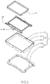
- FIG. 4 is a partial perspective structural schematic diagram of a speaker of the present disclosure
- FIG. 5 is an exploded perspective structural schematic diagram of the speaker shown in FIG. 4 ;
- FIG. 6 is an enlarged diagram of a region B of the speaker shown in FIG. 5 .
- the speaker 100 includes a vibration unit 1 , a magnetic circuit unit 3 , a holder 5 for receiving the vibration unit 1 and the magnetic circuit unit 3 , and a bayonet portion 7 penetrating through the holder 5 .
- the vibration unit 1 includes a diaphragm 11 , a voice coil 13 located at a side of the diaphragm 11 and driving the diaphragm 11 to vibrate and emit sound, and a flexible printed circuit board 15 located at a side of the voice coil 13 facing away from the diaphragm and connected to the voice coil 13 .
- the flexible printed circuit board 15 includes a body portion 151 that supports the voice coil 13 , an extension portion 153 extending from the body portion 151 towards the bayonet portion 7 and passing through the bayonet portion 7 , and a connecting portion 155 that is bent and extends from a distal end of the extension portion 153 along an outer side of the holder 5 .
- the connecting portion 155 is fitted to the outer side of the holder 5 and used for electrical connection with an external circuit.
- the body portion 151 in one aspect, supports the voice coil 13 , and in another aspect, is electrically connected to the voice coil 13 for transmitting an external electrical signal to the voice coil 13 .
- the body portion 151 includes a fixing portion 1511 that is fixedly connected to the voice coil 13 and has a ring shape, an elastic arm 1513 spaced apart from the fixing portion 1511 , and extension arms 1515 respectively extending from the elastic arm 1513 towards the fixing portion 1511 along two opposite ends at a side of the voice coil 13 .
- the elastic arm 1513 , the extension arms 1515 and the fixing portion 1511 form a ring.
- the connecting portion 155 is formed at the elastic arm 1513 .
- the fixing portion 1511 includes a support plate 1517 facing right towards the diaphragm 11 , an inner side-plate 1518 extending from a side of the support plate 1517 facing away from the elastic arm 1513 while being bent towards the diaphragm 11 , and an outer side-plate 1519 extending from a side of the support plate 1517 close to the elastic arm 1513 while being bent towards the diaphragm 11 .
- the support plate 1517 has a ring shape, and the voice coil 13 is sandwiched between the inner side-plate 1518 and the outer side-plate 1519 .
- the outer side-plate is provided with an avoiding notch corresponding to the extension wall 1515 .
- the extension portion 153 and the connecting portion 155 together enclose a buckle structure having a U-shaped cross section, and the connection strength between the flexible printed circuit board 15 and the holder 5 is increased by providing the buckle structure. Moreover, by providing the connecting portion 155 , the flexible printed circuit board 15 can be directly connected to an external electrical device without providing an external pad additionally, thereby saving internal space of the speaker 100 .
- the connecting portion 155 is formed a middle position of the elastic arm 1513 .
- the connecting portion 155 includes a transition portion 1551 extending along the outer side of the holder 5 towards the direction facing away from the diaphragm 11 , and a pad portion 1553 that is bent and extends from an end of the transition portion 1551 facing away from the body portion 151 along the surface of the holder 5 facing away from the diaphragm 11 .
- the pad portion 1553 is arranged opposite to the extension portion 153 and fixedly connected to the surface of the holder 5 facing away from the diaphragm 11 .
- the pad portion 1553 is used for connection with an external circuit.
- the magnetic circuit unit 3 includes a yoke 31 provided at an end of the holder 5 facing away from the diaphragm 11 , a magnet 33 assembled in the center of the yoke 31 , and a pole plate 35 assembled above the magnet 33 .
- the holder 5 may be a metal holder.
- the holder 5 includes a frame body 51 connected to the diaphragm 11 , a support edge 53 provided at an end of the frame body 51 facing away from the diaphragm 11 and connected to the frame body 51 , and a recessed portion 55 formed by recessing from a surface of the frame body 51 facing away from the diaphragm 11 towards the diaphragm 11 .
- the support edge 53 and the recessed portion 55 cooperate to form the bayonet portion 7 .
- the frame body 51 and the support edge 53 are separately formed.
- this is not a limitation to the present disclosure.
- the frame body 51 and the support edge 53 may also be integrally formed.
- the frame body 51 includes two first sidewalls 511 arranged opposite to each other and two second sidewalls 513 arranged opposite to each other.
- the two first sidewalls 511 and the two second sidewalls 513 are connected end to end to form a rectangular frame shape.
- a length of the first sidewall 511 is greater than that of the second sidewall 513 .
- the recessed portion 55 is provided at a middle position of the first sidewall 511 .
- the support edge 53 includes two first support edges 531 respectively connected to the two first sidewalls 511 and two second support edges 533 respectively connected to the two second sidewalls 513 .
- the first support edge 531 is fixedly connected to the elastic arm 1513 and the extension arm 1515 by glue.
- the first support edge 531 is buckled in a buckle structure enclosed by the extension portion 153 and the connecting portion 155 , so as to enhance stability of the connection between the flexible printed circuit board 15 and the holder 5 .
- the first support edge 531 includes a lower surface facing away from the diaphragm 11 , an upper surface arranged opposite to the lower surface, and a side surface connecting the upper surface with the lower surface.
- the extension portion 153 is connected to the upper surface.
- the transition portion 1551 is connected to the side surface, and the pad portion 1553 is connected to the lower surface.
- the number of the bayonet portions 7 is not limited but can be set according to actual needs.
- the number of the bayonet portions 7 is two.
- the number of the recessed portions 55 is also two, and these two recessed portions are respectively provided one the two first sidewalls 511 .
- the two recessed portions 55 and the two first support edges 531 are assembled to form the two bayonet portions 7 .
- the number of the extension portions 153 and the number of the connecting portions 155 are also two.
- the speaker 100 provided by the present disclosure strengthens the fixing connection between the flexible printed circuit board 15 and the holder 5 , and the stability of the speaker 100 is increased.
- the pad portion 1553 connected to the voice coil 13 via the transition portion 1551 , the extension portion 153 and the body portion 151 is provided, so that the voice coil 13 can be directly connected to an external electrical device via the flexible printed circuit board 15 without providing an external pad additionally, thereby saving internal space of the speaker 100 .
Landscapes
- Engineering & Computer Science (AREA)
- Physics & Mathematics (AREA)
- Acoustics & Sound (AREA)
- Signal Processing (AREA)
- Multimedia (AREA)
- Audible-Bandwidth Dynamoelectric Transducers Other Than Pickups (AREA)
- Details Of Audible-Bandwidth Transducers (AREA)
Abstract
Description
Claims (14)
Applications Claiming Priority (3)
| Application Number | Priority Date | Filing Date | Title |
|---|---|---|---|
| CN201821255029.4U CN208638641U (en) | 2018-08-05 | 2018-08-05 | Loudspeaker |
| CN201821255029U | 2018-08-05 | ||
| CN201821255029.4 | 2018-08-05 |
Publications (2)
| Publication Number | Publication Date |
|---|---|
| US20200045431A1 US20200045431A1 (en) | 2020-02-06 |
| US10764686B2 true US10764686B2 (en) | 2020-09-01 |
Family
ID=65740988
Family Applications (1)
| Application Number | Title | Priority Date | Filing Date |
|---|---|---|---|
| US16/524,070 Expired - Fee Related US10764686B2 (en) | 2018-08-05 | 2019-07-28 | Speaker |
Country Status (3)
| Country | Link |
|---|---|
| US (1) | US10764686B2 (en) |
| CN (1) | CN208638641U (en) |
| WO (1) | WO2020029640A1 (en) |
Families Citing this family (4)
| Publication number | Priority date | Publication date | Assignee | Title |
|---|---|---|---|---|
| CN208638641U (en) * | 2018-08-05 | 2019-03-22 | 瑞声科技(新加坡)有限公司 | Loudspeaker |
| CN109889959B (en) * | 2019-05-09 | 2019-07-26 | 瑞声光电科技(常州)有限公司 | Microphone device |
| CN114630247B (en) * | 2020-12-11 | 2024-08-02 | 昆山康龙电子科技有限公司 | Micro speaker with better amplitude stability |
| CN113473335A (en) * | 2021-07-16 | 2021-10-01 | 浙江旗声电子科技股份有限公司 | Small-size high drive power speaker |
Citations (3)
| Publication number | Priority date | Publication date | Assignee | Title |
|---|---|---|---|---|
| US20110293133A1 (en) * | 2010-05-25 | 2011-12-01 | Yan xu-dong | Speaker |
| US20130016874A1 (en) * | 2011-04-04 | 2013-01-17 | Aac Technologies Holdings Inc. | Micro-speaker |
| US20150189442A1 (en) * | 2013-12-31 | 2015-07-02 | AAC Technologies Pte. Ltd. | Electromagnetic transducer |
Family Cites Families (6)
| Publication number | Priority date | Publication date | Assignee | Title |
|---|---|---|---|---|
| CN201290175Y (en) * | 2008-11-07 | 2009-08-12 | 瑞声声学科技(常州)有限公司 | Microtype phonating device |
| JP5322178B2 (en) * | 2009-12-07 | 2013-10-23 | アルパイン株式会社 | Speaker device |
| CN202019447U (en) * | 2011-03-17 | 2011-10-26 | 常州美欧电子有限公司 | Sounder |
| CN203193823U (en) * | 2013-01-18 | 2013-09-11 | 歌尔声学股份有限公司 | Acoustics module |
| CN206923033U (en) * | 2017-06-20 | 2018-01-23 | 瑞声科技(新加坡)有限公司 | Loudspeaker and electronic equipment |
| CN208638641U (en) * | 2018-08-05 | 2019-03-22 | 瑞声科技(新加坡)有限公司 | Loudspeaker |
-
2018
- 2018-08-05 CN CN201821255029.4U patent/CN208638641U/en not_active Expired - Fee Related
-
2019
- 2019-05-23 WO PCT/CN2019/088076 patent/WO2020029640A1/en not_active Ceased
- 2019-07-28 US US16/524,070 patent/US10764686B2/en not_active Expired - Fee Related
Patent Citations (3)
| Publication number | Priority date | Publication date | Assignee | Title |
|---|---|---|---|---|
| US20110293133A1 (en) * | 2010-05-25 | 2011-12-01 | Yan xu-dong | Speaker |
| US20130016874A1 (en) * | 2011-04-04 | 2013-01-17 | Aac Technologies Holdings Inc. | Micro-speaker |
| US20150189442A1 (en) * | 2013-12-31 | 2015-07-02 | AAC Technologies Pte. Ltd. | Electromagnetic transducer |
Also Published As
| Publication number | Publication date |
|---|---|
| US20200045431A1 (en) | 2020-02-06 |
| CN208638641U (en) | 2019-03-22 |
| WO2020029640A1 (en) | 2020-02-13 |
Similar Documents
| Publication | Publication Date | Title |
|---|---|---|
| CN217721456U (en) | coaxial speaker | |
| US10250990B2 (en) | Miniature sounding device | |
| US10341779B2 (en) | Miniature sounding device | |
| US10764686B2 (en) | Speaker | |
| US10750286B2 (en) | Speaker | |
| CN111093138B (en) | sound device | |
| US10764688B2 (en) | Speaker | |
| US10932044B2 (en) | Speaker | |
| CN214413036U (en) | Speakers and Terminal Devices | |
| WO2022143027A1 (en) | Loudspeaker and electronic terminal | |
| US10820113B2 (en) | Speaker | |
| US20170034629A1 (en) | Speaker | |
| US10750289B2 (en) | Speaker | |
| US10743108B2 (en) | Miniature speaker | |
| US20200059732A1 (en) | Multi-function speaker | |
| WO2024044924A1 (en) | Coaxial loudspeaker | |
| CN110418259B (en) | Sound production device monomer, sound production module and electronic terminal | |
| CN217721459U (en) | Coaxial loudspeaker | |
| CN118678270A (en) | Sound producing device and electronic equipment | |
| CN209897257U (en) | Sound production device | |
| US10932055B2 (en) | Speaker | |
| US11589167B1 (en) | Multifunctional electromagnetic transducer | |
| CN209526840U (en) | Loudspeaker and earphone | |
| CN119383536B (en) | speaker | |
| US11057698B2 (en) | Speaker |
Legal Events
| Date | Code | Title | Description |
|---|---|---|---|
| FEPP | Fee payment procedure |
Free format text: ENTITY STATUS SET TO UNDISCOUNTED (ORIGINAL EVENT CODE: BIG.); ENTITY STATUS OF PATENT OWNER: LARGE ENTITY |
|
| AS | Assignment |
Owner name: AAC TECHNOLOGIES PTE. LTD., SINGAPORE Free format text: ASSIGNMENT OF ASSIGNORS INTEREST;ASSIGNOR:ZHANG, GUQING;REEL/FRAME:049981/0782 Effective date: 20190726 |
|
| STPP | Information on status: patent application and granting procedure in general |
Free format text: DOCKETED NEW CASE - READY FOR EXAMINATION |
|
| STPP | Information on status: patent application and granting procedure in general |
Free format text: NOTICE OF ALLOWANCE MAILED -- APPLICATION RECEIVED IN OFFICE OF PUBLICATIONS |
|
| ZAAA | Notice of allowance and fees due |
Free format text: ORIGINAL CODE: NOA |
|
| ZAAB | Notice of allowance mailed |
Free format text: ORIGINAL CODE: MN/=. |
|
| STPP | Information on status: patent application and granting procedure in general |
Free format text: PUBLICATIONS -- ISSUE FEE PAYMENT RECEIVED |
|
| STCF | Information on status: patent grant |
Free format text: PATENTED CASE |
|
| FEPP | Fee payment procedure |
Free format text: MAINTENANCE FEE REMINDER MAILED (ORIGINAL EVENT CODE: REM.); ENTITY STATUS OF PATENT OWNER: LARGE ENTITY |
|
| LAPS | Lapse for failure to pay maintenance fees |
Free format text: PATENT EXPIRED FOR FAILURE TO PAY MAINTENANCE FEES (ORIGINAL EVENT CODE: EXP.); ENTITY STATUS OF PATENT OWNER: LARGE ENTITY |
|
| STCH | Information on status: patent discontinuation |
Free format text: PATENT EXPIRED DUE TO NONPAYMENT OF MAINTENANCE FEES UNDER 37 CFR 1.362 |
|
| FP | Lapsed due to failure to pay maintenance fee |
Effective date: 20240901 |