US10764548B2 - Luminous device using a high-resolution light source - Google Patents
Luminous device using a high-resolution light source Download PDFInfo
- Publication number
- US10764548B2 US10764548B2 US16/333,937 US201716333937A US10764548B2 US 10764548 B2 US10764548 B2 US 10764548B2 US 201716333937 A US201716333937 A US 201716333937A US 10764548 B2 US10764548 B2 US 10764548B2
- Authority
- US
- United States
- Prior art keywords
- measurement
- luminous
- electronic device
- vehicle
- land
- Prior art date
- Legal status (The legal status is an assumption and is not a legal conclusion. Google has not performed a legal analysis and makes no representation as to the accuracy of the status listed.)
- Active
Links
Images


Classifications
-
- H—ELECTRICITY
- H04—ELECTRIC COMMUNICATION TECHNIQUE
- H04N—PICTORIAL COMMUNICATION, e.g. TELEVISION
- H04N9/00—Details of colour television systems
- H04N9/12—Picture reproducers
- H04N9/31—Projection devices for colour picture display, e.g. using electronic spatial light modulators [ESLM]
- H04N9/3191—Testing thereof
- H04N9/3194—Testing thereof including sensor feedback
-
- B—PERFORMING OPERATIONS; TRANSPORTING
- B60—VEHICLES IN GENERAL
- B60Q—ARRANGEMENT OF SIGNALLING OR LIGHTING DEVICES, THE MOUNTING OR SUPPORTING THEREOF OR CIRCUITS THEREFOR, FOR VEHICLES IN GENERAL
- B60Q1/00—Arrangement of optical signalling or lighting devices, the mounting or supporting thereof or circuits therefor
- B60Q1/0017—Devices integrating an element dedicated to another function
-
- B—PERFORMING OPERATIONS; TRANSPORTING
- B60—VEHICLES IN GENERAL
- B60Q—ARRANGEMENT OF SIGNALLING OR LIGHTING DEVICES, THE MOUNTING OR SUPPORTING THEREOF OR CIRCUITS THEREFOR, FOR VEHICLES IN GENERAL
- B60Q1/00—Arrangement of optical signalling or lighting devices, the mounting or supporting thereof or circuits therefor
- B60Q1/02—Arrangement of optical signalling or lighting devices, the mounting or supporting thereof or circuits therefor the devices being primarily intended to illuminate the way ahead or to illuminate other areas of way or environments
- B60Q1/04—Arrangement of optical signalling or lighting devices, the mounting or supporting thereof or circuits therefor the devices being primarily intended to illuminate the way ahead or to illuminate other areas of way or environments the devices being headlights
- B60Q1/06—Arrangement of optical signalling or lighting devices, the mounting or supporting thereof or circuits therefor the devices being primarily intended to illuminate the way ahead or to illuminate other areas of way or environments the devices being headlights adjustable, e.g. remotely-controlled from inside vehicle
- B60Q1/08—Arrangement of optical signalling or lighting devices, the mounting or supporting thereof or circuits therefor the devices being primarily intended to illuminate the way ahead or to illuminate other areas of way or environments the devices being headlights adjustable, e.g. remotely-controlled from inside vehicle automatically
- B60Q1/085—Arrangement of optical signalling or lighting devices, the mounting or supporting thereof or circuits therefor the devices being primarily intended to illuminate the way ahead or to illuminate other areas of way or environments the devices being headlights adjustable, e.g. remotely-controlled from inside vehicle automatically due to special conditions, e.g. adverse weather, type of road, badly illuminated road signs or potential dangers
-
- B—PERFORMING OPERATIONS; TRANSPORTING
- B60—VEHICLES IN GENERAL
- B60Q—ARRANGEMENT OF SIGNALLING OR LIGHTING DEVICES, THE MOUNTING OR SUPPORTING THEREOF OR CIRCUITS THEREFOR, FOR VEHICLES IN GENERAL
- B60Q1/00—Arrangement of optical signalling or lighting devices, the mounting or supporting thereof or circuits therefor
- B60Q1/02—Arrangement of optical signalling or lighting devices, the mounting or supporting thereof or circuits therefor the devices being primarily intended to illuminate the way ahead or to illuminate other areas of way or environments
- B60Q1/04—Arrangement of optical signalling or lighting devices, the mounting or supporting thereof or circuits therefor the devices being primarily intended to illuminate the way ahead or to illuminate other areas of way or environments the devices being headlights
- B60Q1/14—Arrangement of optical signalling or lighting devices, the mounting or supporting thereof or circuits therefor the devices being primarily intended to illuminate the way ahead or to illuminate other areas of way or environments the devices being headlights having dimming means
- B60Q1/1415—Dimming circuits
- B60Q1/1423—Automatic dimming circuits, i.e. switching between high beam and low beam due to change of ambient light or light level in road traffic
-
- F—MECHANICAL ENGINEERING; LIGHTING; HEATING; WEAPONS; BLASTING
- F21—LIGHTING
- F21S—NON-PORTABLE LIGHTING DEVICES; SYSTEMS THEREOF; VEHICLE LIGHTING DEVICES SPECIALLY ADAPTED FOR VEHICLE EXTERIORS
- F21S41/00—Illuminating devices specially adapted for vehicle exteriors, e.g. headlamps
- F21S41/10—Illuminating devices specially adapted for vehicle exteriors, e.g. headlamps characterised by the light source
- F21S41/14—Illuminating devices specially adapted for vehicle exteriors, e.g. headlamps characterised by the light source characterised by the type of light source
- F21S41/141—Light emitting diodes [LED]
- F21S41/155—Surface emitters, e.g. organic light emitting diodes [OLED]
-
- F—MECHANICAL ENGINEERING; LIGHTING; HEATING; WEAPONS; BLASTING
- F21—LIGHTING
- F21S—NON-PORTABLE LIGHTING DEVICES; SYSTEMS THEREOF; VEHICLE LIGHTING DEVICES SPECIALLY ADAPTED FOR VEHICLE EXTERIORS
- F21S41/00—Illuminating devices specially adapted for vehicle exteriors, e.g. headlamps
- F21S41/60—Illuminating devices specially adapted for vehicle exteriors, e.g. headlamps characterised by a variable light distribution
- F21S41/65—Illuminating devices specially adapted for vehicle exteriors, e.g. headlamps characterised by a variable light distribution by acting on light sources
- F21S41/663—Illuminating devices specially adapted for vehicle exteriors, e.g. headlamps characterised by a variable light distribution by acting on light sources by switching light sources
-
- G—PHYSICS
- G06—COMPUTING OR CALCULATING; COUNTING
- G06F—ELECTRIC DIGITAL DATA PROCESSING
- G06F13/00—Interconnection of, or transfer of information or other signals between, memories, input/output devices or central processing units
- G06F13/38—Information transfer, e.g. on bus
- G06F13/42—Bus transfer protocol, e.g. handshake; Synchronisation
-
- H01L27/156—
-
- H01L33/24—
-
- H—ELECTRICITY
- H04—ELECTRIC COMMUNICATION TECHNIQUE
- H04N—PICTORIAL COMMUNICATION, e.g. TELEVISION
- H04N9/00—Details of colour television systems
- H04N9/12—Picture reproducers
- H04N9/31—Projection devices for colour picture display, e.g. using electronic spatial light modulators [ESLM]
- H04N9/3138—Projection devices for colour picture display, e.g. using electronic spatial light modulators [ESLM] using arrays of modulated light sources
-
- H—ELECTRICITY
- H04—ELECTRIC COMMUNICATION TECHNIQUE
- H04N—PICTORIAL COMMUNICATION, e.g. TELEVISION
- H04N9/00—Details of colour television systems
- H04N9/12—Picture reproducers
- H04N9/31—Projection devices for colour picture display, e.g. using electronic spatial light modulators [ESLM]
- H04N9/3141—Constructional details thereof
- H04N9/315—Modulator illumination systems
- H04N9/3155—Modulator illumination systems for controlling the light source
-
- H—ELECTRICITY
- H05—ELECTRIC TECHNIQUES NOT OTHERWISE PROVIDED FOR
- H05B—ELECTRIC HEATING; ELECTRIC LIGHT SOURCES NOT OTHERWISE PROVIDED FOR; CIRCUIT ARRANGEMENTS FOR ELECTRIC LIGHT SOURCES, IN GENERAL
- H05B44/00—Circuit arrangements for operating electroluminescent light sources
-
- H—ELECTRICITY
- H05—ELECTRIC TECHNIQUES NOT OTHERWISE PROVIDED FOR
- H05B—ELECTRIC HEATING; ELECTRIC LIGHT SOURCES NOT OTHERWISE PROVIDED FOR; CIRCUIT ARRANGEMENTS FOR ELECTRIC LIGHT SOURCES, IN GENERAL
- H05B47/00—Circuit arrangements for operating light sources in general, i.e. where the type of light source is not relevant
- H05B47/10—Controlling the light source
- H05B47/105—Controlling the light source in response to determined parameters
- H05B47/11—Controlling the light source in response to determined parameters by determining the brightness or colour temperature of ambient light
-
- H—ELECTRICITY
- H05—ELECTRIC TECHNIQUES NOT OTHERWISE PROVIDED FOR
- H05B—ELECTRIC HEATING; ELECTRIC LIGHT SOURCES NOT OTHERWISE PROVIDED FOR; CIRCUIT ARRANGEMENTS FOR ELECTRIC LIGHT SOURCES, IN GENERAL
- H05B47/00—Circuit arrangements for operating light sources in general, i.e. where the type of light source is not relevant
- H05B47/10—Controlling the light source
- H05B47/105—Controlling the light source in response to determined parameters
- H05B47/115—Controlling the light source in response to determined parameters by determining the presence or movement of objects or living beings
- H05B47/125—Controlling the light source in response to determined parameters by determining the presence or movement of objects or living beings by using cameras
-
- H—ELECTRICITY
- H10—SEMICONDUCTOR DEVICES; ELECTRIC SOLID-STATE DEVICES NOT OTHERWISE PROVIDED FOR
- H10H—INORGANIC LIGHT-EMITTING SEMICONDUCTOR DEVICES HAVING POTENTIAL BARRIERS
- H10H20/00—Individual inorganic light-emitting semiconductor devices having potential barriers, e.g. light-emitting diodes [LED]
- H10H20/80—Constructional details
- H10H20/81—Bodies
- H10H20/819—Bodies characterised by their shape, e.g. curved or truncated substrates
- H10H20/821—Bodies characterised by their shape, e.g. curved or truncated substrates of the light-emitting regions, e.g. non-planar junctions
-
- H—ELECTRICITY
- H10—SEMICONDUCTOR DEVICES; ELECTRIC SOLID-STATE DEVICES NOT OTHERWISE PROVIDED FOR
- H10H—INORGANIC LIGHT-EMITTING SEMICONDUCTOR DEVICES HAVING POTENTIAL BARRIERS
- H10H29/00—Integrated devices, or assemblies of multiple devices, comprising at least one light-emitting semiconductor element covered by group H10H20/00
- H10H29/10—Integrated devices comprising at least one light-emitting semiconductor component covered by group H10H20/00
- H10H29/14—Integrated devices comprising at least one light-emitting semiconductor component covered by group H10H20/00 comprising multiple light-emitting semiconductor components
- H10H29/142—Two-dimensional arrangements, e.g. asymmetric LED layout
-
- B—PERFORMING OPERATIONS; TRANSPORTING
- B60—VEHICLES IN GENERAL
- B60Q—ARRANGEMENT OF SIGNALLING OR LIGHTING DEVICES, THE MOUNTING OR SUPPORTING THEREOF OR CIRCUITS THEREFOR, FOR VEHICLES IN GENERAL
- B60Q2300/00—Indexing codes for automatically adjustable headlamps or automatically dimmable headlamps
- B60Q2300/05—Special features for controlling or switching of the light beam
- B60Q2300/054—Variable non-standard intensity, i.e. emission of various beam intensities different from standard intensities, e.g. continuous or stepped transitions of intensity
-
- B—PERFORMING OPERATIONS; TRANSPORTING
- B60—VEHICLES IN GENERAL
- B60Q—ARRANGEMENT OF SIGNALLING OR LIGHTING DEVICES, THE MOUNTING OR SUPPORTING THEREOF OR CIRCUITS THEREFOR, FOR VEHICLES IN GENERAL
- B60Q2300/00—Indexing codes for automatically adjustable headlamps or automatically dimmable headlamps
- B60Q2300/10—Indexing codes relating to particular vehicle conditions
- B60Q2300/11—Linear movements of the vehicle
- B60Q2300/112—Vehicle speed
-
- B—PERFORMING OPERATIONS; TRANSPORTING
- B60—VEHICLES IN GENERAL
- B60Q—ARRANGEMENT OF SIGNALLING OR LIGHTING DEVICES, THE MOUNTING OR SUPPORTING THEREOF OR CIRCUITS THEREFOR, FOR VEHICLES IN GENERAL
- B60Q2300/00—Indexing codes for automatically adjustable headlamps or automatically dimmable headlamps
- B60Q2300/10—Indexing codes relating to particular vehicle conditions
- B60Q2300/11—Linear movements of the vehicle
- B60Q2300/114—Vehicle acceleration or deceleration
-
- B—PERFORMING OPERATIONS; TRANSPORTING
- B60—VEHICLES IN GENERAL
- B60Q—ARRANGEMENT OF SIGNALLING OR LIGHTING DEVICES, THE MOUNTING OR SUPPORTING THEREOF OR CIRCUITS THEREFOR, FOR VEHICLES IN GENERAL
- B60Q2300/00—Indexing codes for automatically adjustable headlamps or automatically dimmable headlamps
- B60Q2300/10—Indexing codes relating to particular vehicle conditions
- B60Q2300/12—Steering parameters
- B60Q2300/122—Steering angle
-
- B—PERFORMING OPERATIONS; TRANSPORTING
- B60—VEHICLES IN GENERAL
- B60Q—ARRANGEMENT OF SIGNALLING OR LIGHTING DEVICES, THE MOUNTING OR SUPPORTING THEREOF OR CIRCUITS THEREFOR, FOR VEHICLES IN GENERAL
- B60Q2300/00—Indexing codes for automatically adjustable headlamps or automatically dimmable headlamps
- B60Q2300/10—Indexing codes relating to particular vehicle conditions
- B60Q2300/13—Attitude of the vehicle body
- B60Q2300/132—Pitch
-
- B—PERFORMING OPERATIONS; TRANSPORTING
- B60—VEHICLES IN GENERAL
- B60Q—ARRANGEMENT OF SIGNALLING OR LIGHTING DEVICES, THE MOUNTING OR SUPPORTING THEREOF OR CIRCUITS THEREFOR, FOR VEHICLES IN GENERAL
- B60Q2300/00—Indexing codes for automatically adjustable headlamps or automatically dimmable headlamps
- B60Q2300/10—Indexing codes relating to particular vehicle conditions
- B60Q2300/13—Attitude of the vehicle body
- B60Q2300/136—Roll
-
- B—PERFORMING OPERATIONS; TRANSPORTING
- B60—VEHICLES IN GENERAL
- B60Q—ARRANGEMENT OF SIGNALLING OR LIGHTING DEVICES, THE MOUNTING OR SUPPORTING THEREOF OR CIRCUITS THEREFOR, FOR VEHICLES IN GENERAL
- B60Q2300/00—Indexing codes for automatically adjustable headlamps or automatically dimmable headlamps
- B60Q2300/30—Indexing codes relating to the vehicle environment
- B60Q2300/32—Road surface or travel path
-
- B—PERFORMING OPERATIONS; TRANSPORTING
- B60—VEHICLES IN GENERAL
- B60Q—ARRANGEMENT OF SIGNALLING OR LIGHTING DEVICES, THE MOUNTING OR SUPPORTING THEREOF OR CIRCUITS THEREFOR, FOR VEHICLES IN GENERAL
- B60Q2400/00—Special features or arrangements of exterior signal lamps for vehicles
- B60Q2400/20—Multi-color single source or LED matrix, e.g. yellow blinker and red brake lamp generated by single lamp
-
- F—MECHANICAL ENGINEERING; LIGHTING; HEATING; WEAPONS; BLASTING
- F21—LIGHTING
- F21S—NON-PORTABLE LIGHTING DEVICES; SYSTEMS THEREOF; VEHICLE LIGHTING DEVICES SPECIALLY ADAPTED FOR VEHICLE EXTERIORS
- F21S41/00—Illuminating devices specially adapted for vehicle exteriors, e.g. headlamps
- F21S41/10—Illuminating devices specially adapted for vehicle exteriors, e.g. headlamps characterised by the light source
- F21S41/14—Illuminating devices specially adapted for vehicle exteriors, e.g. headlamps characterised by the light source characterised by the type of light source
- F21S41/141—Light emitting diodes [LED]
-
- H01L33/0075—
-
- H01L33/32—
-
- H—ELECTRICITY
- H04—ELECTRIC COMMUNICATION TECHNIQUE
- H04L—TRANSMISSION OF DIGITAL INFORMATION, e.g. TELEGRAPHIC COMMUNICATION
- H04L12/00—Data switching networks
- H04L12/28—Data switching networks characterised by path configuration, e.g. LAN [Local Area Networks] or WAN [Wide Area Networks]
- H04L12/40—Bus networks
- H04L2012/40267—Bus for use in transportation systems
- H04L2012/40273—Bus for use in transportation systems the transportation system being a vehicle
-
- H—ELECTRICITY
- H05—ELECTRIC TECHNIQUES NOT OTHERWISE PROVIDED FOR
- H05B—ELECTRIC HEATING; ELECTRIC LIGHT SOURCES NOT OTHERWISE PROVIDED FOR; CIRCUIT ARRANGEMENTS FOR ELECTRIC LIGHT SOURCES, IN GENERAL
- H05B45/00—Circuit arrangements for operating light-emitting diodes [LED]
- H05B45/10—Controlling the intensity of the light
-
- H—ELECTRICITY
- H10—SEMICONDUCTOR DEVICES; ELECTRIC SOLID-STATE DEVICES NOT OTHERWISE PROVIDED FOR
- H10H—INORGANIC LIGHT-EMITTING SEMICONDUCTOR DEVICES HAVING POTENTIAL BARRIERS
- H10H20/00—Individual inorganic light-emitting semiconductor devices having potential barriers, e.g. light-emitting diodes [LED]
- H10H20/01—Manufacture or treatment
- H10H20/011—Manufacture or treatment of bodies, e.g. forming semiconductor layers
- H10H20/013—Manufacture or treatment of bodies, e.g. forming semiconductor layers having light-emitting regions comprising only Group III-V materials
- H10H20/0137—Manufacture or treatment of bodies, e.g. forming semiconductor layers having light-emitting regions comprising only Group III-V materials the light-emitting regions comprising nitride materials
-
- H—ELECTRICITY
- H10—SEMICONDUCTOR DEVICES; ELECTRIC SOLID-STATE DEVICES NOT OTHERWISE PROVIDED FOR
- H10H—INORGANIC LIGHT-EMITTING SEMICONDUCTOR DEVICES HAVING POTENTIAL BARRIERS
- H10H20/00—Individual inorganic light-emitting semiconductor devices having potential barriers, e.g. light-emitting diodes [LED]
- H10H20/80—Constructional details
- H10H20/81—Bodies
- H10H20/822—Materials of the light-emitting regions
- H10H20/824—Materials of the light-emitting regions comprising only Group III-V materials, e.g. GaP
- H10H20/825—Materials of the light-emitting regions comprising only Group III-V materials, e.g. GaP containing nitrogen, e.g. GaN
-
- Y—GENERAL TAGGING OF NEW TECHNOLOGICAL DEVELOPMENTS; GENERAL TAGGING OF CROSS-SECTIONAL TECHNOLOGIES SPANNING OVER SEVERAL SECTIONS OF THE IPC; TECHNICAL SUBJECTS COVERED BY FORMER USPC CROSS-REFERENCE ART COLLECTIONS [XRACs] AND DIGESTS
- Y02—TECHNOLOGIES OR APPLICATIONS FOR MITIGATION OR ADAPTATION AGAINST CLIMATE CHANGE
- Y02B—CLIMATE CHANGE MITIGATION TECHNOLOGIES RELATED TO BUILDINGS, e.g. HOUSING, HOUSE APPLIANCES OR RELATED END-USER APPLICATIONS
- Y02B20/00—Energy efficient lighting technologies, e.g. halogen lamps or gas discharge lamps
- Y02B20/40—Control techniques providing energy savings, e.g. smart controller or presence detection
Definitions
- the invention relates to the field of luminous land-vehicle devices, i.e. devices allowing, during use of the vehicle, light to be projected so as to illuminate the road or the passenger compartment and/or so as to allow the vehicle to be made more visible.
- luminous devices are position lights or low-beam and/or high-beam lights (commonly referred to as “headlights”).
- Land vehicles are equipped with luminous devices, in particular lighting and/or signaling devices, such as headlamps or rear lights, that are intended to illuminate the road in front of the vehicle at night or in case of low visibility. They may also serve to illuminate the passenger compartment of the vehicle.
- luminous devices may comprise one or more luminous modules. Each lighting function may be performed by one or more modules.
- electroluminescent light sources solid-state lighting arrays for example
- These light sources may consist of light-emitting diodes or LEDs, of organic light-emitting diodes or OLEDs, or even of polymer light-emitting diodes or PLEDs.
- These light sources have advantages in particular in terms of bulk and lifetime with respect to conventional light sources such as incandescent bulbs for example.
- high-pixel-density electroluminescent light sources also known as monolithic LED arrays
- the LEDs are also referred to as pixels.
- These high-density light sources make it possible to select with a very great precision which zones of a scene are illuminated and with which light intensity.
- a monolithic array comprises several thousand LEDs that are located on the same substrate, the LEDs being separated from the others by lanes or streets. Each of the LEDs is electrically independent from the others and therefore illuminates autonomously from the other LEDs of the array.
- a luminous land-vehicle device for illuminating a scene.
- This device comprises a monolithic electroluminescent source comprising electroluminescent elements, an optical system arranged to form an image of the monolithic electroluminescent source, and an electronic device able to—receive at least one first measurement regarding at least one physical parameter of the vehicle—receive at least one second measurement regarding at least one physical parameter of the scene, and—control the electroluminescent elements of the source depending on the received first and/or second measurements.
- the luminous device may comprise one or more of the following features combined together:
- a method for illuminating a scene with the above luminous device comprising steps in which:
- This method may furthermore comprise:
- FIG. 1 schematically shows a first example of a luminous module able to be used in the luminous device according to the invention
- FIG. 2 schematically shows a second example of a luminous module able to be used in the luminous device according to the invention
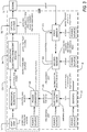
- FIG. 3 schematically shows one example of a luminous device according to the invention
- FIG. 4 shows a flowchart of one example of a method for illuminating a scene according to the invention.
- FIG. 3 shows one example of a luminous device 30 according to the invention.
- the luminous device may be included in a land vehicle in order to illuminate a scene 32 , i.e. the volume of space that needs to be illuminated, a road for example.
- the luminous device 30 comprises a monolithic electroluminescent source that is a solid-state lighting array that comprises a high number of electroluminescent elements; typically this number is higher than 1000 electroluminescent elements.
- An electroluminescent element may be, non-limitingly, a light-emitting diode (LED), an organic light-emitting diode (OLED) or a polymer light-emitting diode (PLED).
- the electroluminescent source is therefore a semiconductor light source and it includes a substrate on which the electroluminescent elements are placed.
- An electroluminescent element is more generally called a pixel. Therefore, the light source comprises a plurality of pixels deposited on or extending from the first face of the substrate.
- the electroluminescent elements may each be semiconductor, i.e. they may each include at least one semiconductor.
- the electroluminescent elements may mainly be made of semiconductor. This semiconductor may be the same as or different from the material of the substrate.
- the electroluminescent elements may more generally all be produced from the same material or materials.
- the electroluminescent elements may be of the same nature and, for example, be substantially identical or similar. All the electroluminescent elements may be positioned to form a regular pattern, a grid for example.
- the elements are electroluminescent. This means that they emit light when the material of the electroluminescent elements is supplied with electricity.
- the electroluminescent elements use electroluminescence to emit light. Electroluminescence is an optical and electrical effect during which a material emits light in response to an electrical current flowing therethrough, or to a strong electric field. It is to be distinguished from light emission due to temperature (incandescence) or to the action of chemical products (chemiluminescence). A pixel may be said to be turned on when an electroluminescent element emits light.
- the electroluminescent source is a monolithic electroluminescent source, also referred to as a high-pixel-density solid-state lighting array.
- a monolithic array comprises hundreds or thousands of electroluminescent elements that are located on the same substrate, and preferably on the same face of the substrate, which may for example be made of sapphire.
- the LEDs of the monolithic array are separated from one another by lanes or streets.
- the monolithic array is therefore a grid of electroluminescent elements or even a grid of pixels.
- the electroluminescent elements may be LEDs; in this case, a monolithic LED array is spoken of. Any other technology may be envisioned, such as for example organic light-emitting diodes (OLEDs) or polymer light-emitting diodes (PLEDs), etc.
- OLEDs organic light-emitting diodes
- PLEDs polymer light-emitting diodes
- the monolithic electroluminescent source is a high-density source, i.e. it comprises a very high number of electroluminescent elements, at least several hundred electroluminescent elements.
- the source includes more than 500 electroluminescent elements on the same substrate.
- the pixel density is preferably higher than 500 pixels per cm 2 . It is typically comprised between 500 and 2500 pixels per cm 2 . It will be understood that the pixel density of a light source of high light-element density may be higher than 2500 pixels per cm 2 .
- Each of the electroluminescent elements of the array is electrically independent from the others and emits or does not emit light independently from the other elements of the array.
- Each element of the array is controlled individually by an electronic circuit called a driver.
- the driver manages the supply of electrical power to the monolithic array, this amounting to saying that it individually manages the supply of electrical power to each electroluminescent element.
- electroluminescent elements may be grouped together electrically, for example by supplying them with electrical power via a parallel or series set-up, in order to decrease the number of elements to be managed.
- the groups may comprise between two and four electroluminescent elements, this number allowing a sufficiently pixelized light beam to be preserved.
- the driver is therefore an electronic device that is able to control the elements of a monolithic array of electroluminescent elements.
- a plurality of drivers may be used to control the electroluminescent elements of the array.
- the monolithic electroluminescent source may be comprised in a luminous module 300 . It will be understood that the luminous module may have a plurality of monolithic electroluminescent sources. A plurality of luminous modules comprising such a monolithic electroluminescent source may be integrated into the luminous device according to the invention. The term “luminous module” therefore designates at least one monolithic electroluminescent source.
- FIG. 1 schematically shows an example of a luminous module.
- the luminous motor-vehicle module 10 comprises a monolithic electroluminescent source 12 , for example an LED array, a PCB 14 (acronym of printed circuit board) that bears the source 12 and the device 19 for controlling the electroluminescence elements of the monolithic light source 12 . Any other holder other than a PCB may be envisioned.
- the luminous module may furthermore comprise at least one heat sink 18 that may be arranged directly or indirectly on the source 12 . In this example, the heat sink 18 is arranged indirectly on the source since the PCB 14 and a thermal interface 16 are located between the heat sink 18 and the source 12 .
- the heat sink allows the heat of the electroluminescent source that the latter transmits to the PCB during use of a luminous module to be transferred.
- the heat sink allows heat to be dissipated via an interaction with the holder 14 of the monolithic electroluminescent source; i.e. the heat sink receives the heat produced by the electroluminescent source.
- the heat sink 18 is thus in thermal communication with the PCB 14 , which itself is in thermal communication with the heat source 12 .
- the transmission may be ensured by the fact that the heat sink is in one example arranged directly against the PCB 14 . This means that the heat sink makes physical (i.e. material) contact with the PCB.
- the heat sink 18 may however alternatively be arranged on the interposer via an intermediate element that improves heat transfer.
- This intermediate element is also called the thermal interface 16 .
- the intermediate element 16 may for example comprise a thermal grease or a phase-change material.
- the intermediate element may comprise copper, and for example the thermal interface 16 is a copper plate.
- a second example of a luminous module which comprises a so-called “3D” monolithic electroluminescent source, i.e. the electroluminescent sources are not solely deposited on the substrate of the source: the electroluminescent elements extend from the substrate of the source, will now be discussed.
- the luminous module comprises a high number of semiconductor electroluminescent sources including a substrate mainly made of semiconductor. It is thus possible to make reference to the substrate using the expression “semiconductor substrate”.
- the substrate may include one or more other materials, for example non-semiconductors. Therefore, the luminous module comprises at least a plurality of such elements extending from the first face of the substrate.
- the elements may be grouped together into one or more sets.
- Each set consists of a plurality of elements extending from a respective segment of the first face of the substrate.
- the electroluminescent elements may therefore be distributed in various light-emitting zones. In one example, these various zones may be selectively activatable.
- the elements may have a rod-like general shape and thus be called “rods”.
- the electroluminescent elements may be supplied with electricity via the substrate from one side (e.g. the substrate for example forming the cathode) and via a layer of electrical conductor that electrically connects the electroluminescent elements together on the other side (e.g. the layer of electrical conductor forming for example the anode).
- the contact between the semiconductor of each electroluminescent element and the semiconductor of the substrate may therefore be suitable for electrical conduction.
- the layer of electrical conductor may cover the electroluminescent elements.
- the layer of electrical conductor may also cover each segment of surface of the substrate from which the electroluminescent elements extend, or any surface or face of the substrate from which the sets of electroluminescent elements extend.
- the layer of electrical conductor may be electrically insulated from the semiconductor of the substrate by any means. This allows the electroluminescent elements to be supplied with electricity via the substrate. Thus, it is possible to supply the electroluminescent elements with electricity simply, i.e. by giving the semiconductor of the substrate one polarity and the layer of electrical conductor the other polarity.
- the electroluminescent source may be manufactured using a process comprising at least a step of providing the substrate, then a step of forming the rods integrally with the substrate by growth from the substrate.
- the layer of electrical conductor may be produced via a step of depositing a finishing metal, for example copper in order to allow the rods to be controlled.
- This step may also comprise creating aluminium or copper pads on one face of the substrate, said pads being suitable for wire or ribbon bonding between the source and the control component.
- Wire or ribbon bonding is one of the techniques used to form electrical connections between the electroluminescent source and the power supply device of the source.
- An electrical connection is simply produced by bonding a wire (or ribbon) to the two connection pads provided for this purpose on each of the elements. The bond may be achieved ultrasonically.
- the material of the wire or ribbon may be aluminium, gold or copper.
- the diameter of the wire may be about 20 ⁇ m.
- a ribbon of rectangular cross section may also be used.
- FIG. 2 shows an example of such a so-called “3D” monolithic electroluminescent light source.
- the light source S here shown in cross section, comprises a substrate 210 from which rods 211 , 212 extend in a privileged direction.
- This substrate 210 is, in particular in this example, a silicon substrate, this having a cost much lower than that of conventional LEDs, in which the substrates are made of sapphire.
- the rods 211 , 212 may be obtained by crystalline growth on this substrate 210 .
- the rods 211 , 212 are arranged so as to form rods made of electroluminescent semiconductor.
- the rods 211 , 212 may for example be formed essentially from gallium nitride.
- these rods 211 , 212 comprise a core made of a semiconductor able to be doped in electrons, around which is formed a first layer made of a semiconductor able to present deficits in electrons, in this case a layer doped in “holes” or in positive charges is sometimes spoken of. At the interface of this core and this first layer, an intermediate layer forms in which the electrons and the deficits in electrons recombine.
- each rod 211 , 212 is an electroluminescent semiconductor element.
- a nucleation layer 219 is formed on the substrate 210 and around the rods 211 , 212 .
- the rods 211 , 212 are, in this example, distant by about 30 ⁇ m and each have a height, measured from the nucleation layer 219 to the top thereof, of 2.5 ⁇ m. Their diameter is 1.5 ⁇ m. It will be understood that these values are given by way of indication and may vary.
- the light source S therefore essentially comprises a substrate 210 forming a plate bristling with a multitude of small rods 211 , 212 that are electroluminescent and of submillimetre size, i.e. the largest dimension thereof is smaller than one millimetre.
- the light source S is divided into a plurality of luminous zones 201 , 202 that are separated by divisions 221 that correspond to partitions of the set of all the rods 211 , 212 .
- each rod 211 , 212 of a given zone 201 , 202 is deposited an electrically conductive layer that electrically links these rods, thus forming a separate anode 225 , 226 for each of the luminous zones 201 , 202 .
- the four anodes 225 , 226 thus formed make contact with the nucleation layer 219 , which itself makes contact with the cathode formed by the substrate 210 .
- each anode is connected to one or more positive terminals by a connecting means 220 , which is intended to be connected to the positive terminal of an electrical power source (not shown) of a vehicle.
- the cathode 210 is connected to the negative terminal of the connecting means 220 .
- the activating means therefore allows electrical power to be supplied to each of these luminous zones 201 , 202 .
- this light source S by selectively activating its luminous zones 201 , 202 , via the activating means 220 .
- This driving may also be achieved via a specific means separate from the luminous device, or indeed, as in this example, by a driver 229 that is integrated into the luminous device.
- the driving is achieved directly via a driver 229 .
- the latter is connected on the one hand to the connecting means 220 and on the other hand to the connector C.
- the connecting means 220 is for its part connected to each anode 225 , 226 , via electrical conductors.
- the driver 229 and the light source S are mounted on the same printed circuit board (not shown).
- the electrical conductors are formed by electronic tracks of this printed circuit board. Likewise, other electronic tracks connect the connecting means 220 to the driver 229 .
- the luminous efficacy of the luminous zones 201 , 202 may be improved by depositing a reflective layer 217 , 218 on the nucleation layer 219 .
- This reflective layer 217 , 218 is for example deposited on the nucleation layer 219 before growth of the rods, then holes are produced in this reflective layer 217 , 218 , and in the nucleation layer, before growth of the rods 211 , 212 , 213 , 214 on the substrate 10 .
- the rods of the luminous zones may have the following features:
- a diameter comprised between 1.4 ⁇ m and 1.6 ⁇ m, for example 1 ⁇ m
- a height comprised between 2 ⁇ m and 10 ⁇ m, for example 8 ⁇ m,
- each rod comprised between 3 and 10 ⁇ m.
- the light source S may comprise a light converter 223 arranged above the rods 211 , 212 .
- a light converter comprises at least one luminescent material designed to absorb at least some of at least one exciting emission emitted by a light source and to convert at least some of said absorbed exciting emission into a luminous emission having a wavelength different from that of the exciting emission.
- the material may for example be cerium—or europium-doped YAG.
- the light source is a high-density source, i.e. it comprises a very high number of sets of electroluminescent elements, at least several hundred sets of electroluminescent elements.
- the luminous device according to the invention also comprises an optical system 302 that is arranged to form an image of the monolithic electroluminescent source.
- the image may be a real image or indeed even a virtual image.
- the optical system is therefore placed downstream of the monolithic electroluminescent source in the direction of travel of the emitted light.
- the optical system may comprise a forming optic, i.e. at least one of the rays emitted by the light source is deviated by the forming optic.
- the term “deviated” means that the direction of entrance of the light ray into the forming optic is different from the direction of exit of the light ray from the forming optic.
- the optical system comprises at least one optical element such as one or more lenses, or one or more reflectors, one or more light guides or a combination of these possibilities.
- the optical system 302 is not comprised in the luminous module 300 . This allows the optical system to be preserved when the luminous module is faulty. It will be understood that the system could be comprised in the luminous module 300 .
- the optical system may have a resolution that is lower than or equal to 0.25 degrees and a field larger than or equal to 5 degrees.
- the luminous device according to the invention comprises one (or more than one) electronic device(s) 330 able to control the electroluminescent elements of the electroluminescent source.
- an electronic device may for example be an integrated circuit or a power converter.
- a power converter is a device for converting a supply of electrical power obtained from a vehicle electrical network into an electrical supply suitable for the performance of a desired luminous function, and optionally for delivering said suitable electrical supply to an electroluminescent source for the performance of said desired luminous function.
- An integrated circuit also called an electronic chip, is an electronic component that performs one or more electronic functions and that may incorporate several types of basic electronic components, for example in a small volume (i.e. on a small chip). This makes the circuit easy to implement.
- the integrated circuit may for example be an ASIC or an ASSP.
- An ASIC (acronym of application-specific integrated circuit) is an integrated circuit developed for at least one specific application (i.e. for a customer).
- An ASIC is therefore a specialized (microelectronic) integrated circuit. In general, it has many unique or made-to-measure functionalities.
- An ASSP (acronym of application-specific standard product) is an integrated (microelectronic) electronic circuit having many functionalities for addressing an application that is generally standardized.
- An ASIC is designed for a more particular (specific) need than an ASSP.
- Electricity is supplied to the electroluminescent source, and therefore to the electroluminescent elements, via the electronic device, which itself is supplied with electricity for example using at least one connector that connects it to a source of electricity.
- the electronic device thus supplies the electroluminescent elements with electricity.
- the electronic device is thus able to control the electroluminescent elements.
- the luminous modules of the examples of FIGS. 1 and 2 each comprise at least one driver 19 , 229 (also called a driver) integrated into the luminous module.
- the one or more electronic devices 330 configure the one or more drivers of the luminous module: they transmit a configuration to the one or more drivers of the luminous module in order that they drive the turn-on of one or more electroluminescent elements of the source. It will be understood that the one or more electronic devices 330 may conversely transmit a configuration to the one or more drivers of the luminous module in order that they drive the turn-off of one or more electroluminescent elements of the source.
- the driving is achieved directly by the electronic device, which will configure the one or more drivers of the monolithic electroluminescent source.
- the electronic device 330 is able to directly control the electroluminescent elements of the source, or alternatively it is able to indirectly control the electroluminescent elements of the source by configuring the one or more drivers of the one or more luminous modules, a combination of these possibilities also being envisionable.
- the electroluminescent elements are configured depending on measurements received by the electronic device 330 , i.e. the electronic device determines which electroluminescent elements of the monolithic electroluminescent source must be turned on depending on parameters that it receives. More precisely, the electronic device 330 receives measurements of these parameters. The measurements used will now be discussed.
- the electronic device 330 is able to receive first measurements regarding at least one physical parameter of the vehicle.
- a physical parameter of the vehicle is any measurable characteristic of the vehicle, and it in particular varies when the vehicle is moving.
- a physical parameter of the vehicle may be, but is not limited to, the speed of the vehicle, the acceleration of the vehicle, the drift angle of the steerable wheels (or of the steerable wheel) of the vehicle, the roll angle of the vehicle, the pitch angle of the vehicle, the geoposition of the vehicle (GPS coordinates or coordinates provided by another system), the compression/decompression of the suspension of the vehicle, the activation of a brake pedal, clutch pedal, accelerator, etc.
- the electronic device 330 is also able to receive second measurements that relate to at least one physical parameter of the scene illuminated by the optical system ( 302 ).
- This physical parameter of the scene may be light emitted by the scene, for example light emitted by a white luminous strip on the road illuminated by the optical system 302 or even light reflected and/or emitted by another vehicle, a streetlamp, a road sign, etc.
- the physical parameter of the scene may also comprise cartographic information of the latter, which may for example be delivered by a GPS guidance system. This cartographic information may comprise, but is not limited to, the curvature of the road, altitude, the presence of an intersection, the presence of a piece of infrastructure (bridge, tunnel, etc.), etc.
- the electronic device 330 may receive the first and/or second measurements synchronously. It is therefore a question of a transmission mode employing a synchronous link, in which the emitter of the measurements and the receiver of the measurements are clocked by the same clock. The receiver continuously receives (even when no bits are transmitted) information at the rate at the which the emitter sends it.
- the electronic device 330 may receive the first and/or second measurements asynchronously. It is therefore a question of a transmission mode employing an asynchronous link, in which the emitter of the measurements sends to the receiver the data of the measurements and the clock signal.
- the electronic device 330 may receive the first measurements synchronously and the second measurements asynchronously, or indeed vice versa.
- the exchanges of information in which the luminous device according to the invention participates are based on asynchronous exchanges, which facilitate the overall management of the transmissions and of the computations carried out by the electronic device 330 .
- Synchronous exchanges may also take place—although they are more rapid, they require more data to be transmitted.
- the measurements of the physical parameters received by the electronic device 330 are carried out by sensors that may belong to the device, or indeed in contrast that do not belong to the device.
- the vehicle comprises many sensors that measure physical parameters of the vehicle and it is not necessary to add any more.
- the luminous device according to the invention will therefore preferably exploit the measurements made by these sensors in order to not complexify the construction of the vehicle.
- the speed of the vehicle is continuously measured by a speed sensor that transmits it to the on-board computer of the vehicle, which in turn may transmit, for example asynchronously, the measured values to the electronic device 330 .
- the same goes for other physical parameters of the vehicle such as its acceleration, the drift angle of its steerable wheels, its roll, the pitch of the vehicle, its geoposition, the compression/decompression of the suspension of the vehicle, etc.
- there are as many types of first measurements as there are types of sensors of physical parameters of the vehicle.
- the device according to the invention is able to determine with precision the orientation of the vehicle using information regarding (i) the pitch angle of the vehicle, which may be delivered by sensors of acceleration, deceleration, braking, suspension, and (ii) regarding the roll angle of the vehicle, which may be delivered by sensors measuring the angle of the steerable wheels or the angle of the steering wheel or the speed of the vehicle or sideways accelerations.
- the pitch angle of the vehicle which may be delivered by sensors of acceleration, deceleration, braking, suspension
- the roll angle of the vehicle which may be delivered by sensors measuring the angle of the steerable wheels or the angle of the steering wheel or the speed of the vehicle or sideways accelerations.
- these parameters may be captured by a camera 310 placed on the vehicle, and/or by an infrared camera and/or a radar and/or a lidar.
- the infrared camera, radar and lidar allow non-reflective objects such as for example pedestrians or animals to be detected.
- the camera produces an image stream, for example of 25 to 30 images per second. Each image produced by the camera captures the luminosity of objects present in the illuminated scene.
- the camera as sensor, may be associated with a unit 312 for analysing the image stream that it produces. Specifically, the images contain a very large amount of information that may be too much for the electronic device 330 to process.
- the analysing unit 312 extracts the relevant information of each image of the image stream produced by the camera, for example using image-processing algorithms.
- the relevant information may be, but is not limited to, the detection of objects such as an oncoming vehicle, a road user (motorcyclist, cyclist, etc.), a pedestrian, an animal, traffic signals such as road markings, road signs, etc.
- the data contained in the images may therefore be segmented and categorized in order to allow the electronic device to determine what objects are present and what is the location of each of the objects with respect to the vehicle.
- Image segmentation is an image-processing operation, the aim of which is to group pixels together according to predefined criteria.
- the pixels are thus grouped into regions, which form a tiling or a partition of the image.
- the assignment of a moving vehicle to a first segment may be based on detection of its front lights or its rear lights.
- the electronic device will determine whether it is necessary to illuminate it or not, or even with which intensity to illuminate it.
- Physical parameters may also be measured by sensors that are not placed on the vehicle. For example, information regarding traffic signals may be transmitted to the vehicle by terminals located in proximity to the road. Furthermore, information regarding traffic (for example a hazard on the route of the vehicle) may be transmitted via a telecommunication system such as a mobile telecommunication network.
- a telecommunication system such as a mobile telecommunication network.
- the analysing unit 312 may also use segmentation results computed beforehand to make a prediction on the nature of the objects present and their location.
- Predictive image-analysing filters may be used, for example a Kalman filter or a particle filter.
- the camera comprises an analysing unit 312 , it is the latter that transmits to the electronic device 330 the performed measurements—in this case, it is more precisely a question of information extracted from the images produced by the camera.
- the information is preferably transmitted asynchronously; synchronous transmission is however envisionable.
- the transmission is carried out using one or more communication buses, for example using communication buses already present in the vehicle.
- any type of communication bus is envisionable, but wired transmission is preferred for reasons of transmission rapidity and reliability.
- a standardized controller area network or CAN i.e. a system of asynchronous series buses
- ISO 11898 may be used.
- each of the sensors measuring one physical parameter of the vehicle is able to deliver a measurement more frequently than the camera: specifically, the analysis of the images produced by the camera involves processing operations that require many computations that take more time than a simple acquisition of a value of one physical parameter.
- the refresh frequency of the sensors measuring the physical parameters of the vehicle may be about 100-200 hertz (Hz), whereas the refresh frequency of the camera may be three times lower (i.e. about 25-30 Hz).
- the refresh frequency of the sensors measuring the physical parameters of the vehicle is 20 Hz
- the refresh frequency of the sensors measuring the parameters of the scene is 5 Hz.
- the electronic device may receive at least three times more measurements per sensor of the physical parameters of the vehicle and per unit time than physical scene parameters captured using a camera.
- the measurements of the physical parameters of the vehicle may be used by the electronic device to configure the electroluminescent elements and the measurements obtained by the camera may be used to correct, if necessary, the configurations obtained with the measurements of the physical parameters.
- the higher refresh frequency of the measurements of the physical parameters allows the turn-on or turn-off of the elements of the source to be rapidly controlled.
- the electronic device may not refresh the configuration of the electroluminescent elements of the source on each new arrival of received measurements in order to decrease the number of configurations that must be transmitted to the one or more drivers of the luminous module.
- step S 100 the electronic device receives at least one first measurement of at least one physical parameter of the vehicle.
- each sensor transmits a measurement as soon as it has been acquired via a suitable means, for example an asynchronous communication bus connecting it to the electronic device.
- step 102 the electronic device determines which electroluminescent elements must be turned on depending on one or more than one of the received measurements of the physical parameters of the vehicle.
- step S 104 the electronic device determines which electroluminescent elements must be turned on depending on one or more than one of the received measurements. This step may be carried out as soon as a new measurement is delivered to the electronic device, or indeed it may wait to have received at least one measurement from each of the sensors. Another possibility is that the electronic device perform the determination at a given frequency, independently of whether or not a new measurement has been received from all or some of the sensors present.
- a configuration of the electroluminescent elements that must be turned on is obtained, which is sent to the one or more drivers of the monolithic electroluminescent source for execution.
- the lighting provided by the vehicle is modified if the measurements delivered by the sensors of the physical parameters of the vehicle mean a correction is required.
- steps S 100 , S 102 , S 104 are repeated so that the lighting is configured solely depending on the physical parameters of the vehicle.
- step S 110 the electronic device receives at least one second measurement of at least one physical parameter of the scene.
- the analysing unit 312 transmits the result of the analysis of one or more images of the image stream generated by the camera.
- the electronic device may receive at least one third measurement of at least one physical parameter of the scene (step S 112 ) that is different from the physical parameter of the second measurement.
- a camera may have delivered the second measurement and an infrared camera a third measurement.
- the second and third measurements are fused (step S 114 ) in order to provide consolidated information on the physical parameters of the scene.
- step 122 the electronic device determines which electroluminescent elements must be turned on depending on the received second measurement or indeed depending on the fused second and third measurements.
- step S 122 no new measurements were delivered by the sensors of the physical parameters of the vehicle (step S 120 ) after step S 110 or S 114 was carried out. A correction is thus applied using information gathered by the camera to the configuration computed beforehand on the basis of the first measurements.
- a step S 132 may be carried out in which the electronic device determines which electroluminescent elements must be turned on depending on the received second measurement—or indeed depending on the fused second and third measurements—and depending on new measurements that were delivered by the sensors of the physical parameters of the vehicle (step 130 ) to the electronic device after step S 110 or S 114 was carried out, i.e. after a second measurement or a third measurement was received.
- the new configuration of the electroluminescent elements that must be turned on is transmitted in turn to the one or more drivers of the monolithic electroluminescent source for execution, in step S 140 .
- the lighting produced by the light source is modified.
- step S 100 The method is repeated starting with step S 100 until there is no longer any need for the luminous device to illuminate the scene, the luminosity of the scene captured by the camera for example being judged to be suitable by the electronic device.
Landscapes
- Engineering & Computer Science (AREA)
- Physics & Mathematics (AREA)
- Multimedia (AREA)
- Signal Processing (AREA)
- General Engineering & Computer Science (AREA)
- Microelectronics & Electronic Packaging (AREA)
- Optics & Photonics (AREA)
- Mechanical Engineering (AREA)
- Theoretical Computer Science (AREA)
- General Physics & Mathematics (AREA)
- Lighting Device Outwards From Vehicle And Optical Signal (AREA)
- Electroluminescent Light Sources (AREA)
Abstract
Description
- the electronic device comprises at least one power converter and/or one integrated circuit;
- the electronic device receives the first and second measurements asynchronously;
- the reception frequency of the first measurements is at least three times higher than that of the second measurements;
- at least one first sensor that generates the first measurements;
- at least one second sensor that generates the second measurements;
- the second sensor is a camera that produces an image stream;
- the second sensor furthermore comprises a unit for analysing the image stream produced by the camera;
- the analysing unit carries out segmenting operations on the images of the image stream;
- a heatsink arranged on at least the monolithic electroluminescent source;
- the optical system has a resolution that is lower than or equal to 0.25 degrees and a field larger than or equal to 5 degrees.
- (i) the electronic device receives a first measurement of at least one physical parameter of the vehicle;
- (ii) the electronic device determines which electroluminescent elements of the monolithic electroluminescent source must be turned on depending on the received first measurement;
- (iii) the electronic device configures at least the electroluminescent elements determined in step (ii) so that they emit light.
- after step (iii), steps in which:
- (iv) the electronic device receives a second measurement of at least one physical parameter of the scene;
- (v) the electronic device determines which electroluminescent elements of the monolithic electroluminescent source must be turned on depending on the received second measurement;
- (vi) the electronic device configures at least the electroluminescent elements determined in step (v) so that they emit light.
- after step (iii), steps in which:
- (iv) the electronic device receives second and third measurements of at least two physical parameters of the scene;
- (v) the received second and third measurements are fused;
- (vi) the electronic device receives a new first measurement of at least one physical parameter of the vehicle;
- (vii) the electronic device determines which electroluminescent elements of the monolithic electroluminescent source must be turned on depending on the received new first measurement and the received second and third measurements;
- (viii) the electronic device configures at least the electroluminescent elements determined in step (vii) so that they emit light.
- steps (i), (ii) and (iii) are repeated provided that a second measurement of a physical parameter of the scene has not been received.
Claims (19)
Applications Claiming Priority (3)
| Application Number | Priority Date | Filing Date | Title |
|---|---|---|---|
| FR1658652A FR3055946B1 (en) | 2016-09-15 | 2016-09-15 | LIGHT DEVICE USING HIGH RESOLUTION LIGHT SOURCE |
| FR1658652 | 2016-09-15 | ||
| PCT/EP2017/068935 WO2018050338A1 (en) | 2016-09-15 | 2017-07-26 | Light device using a high-resolution light source and method for illuminating a scene with said device |
Publications (2)
| Publication Number | Publication Date |
|---|---|
| US20190215502A1 US20190215502A1 (en) | 2019-07-11 |
| US10764548B2 true US10764548B2 (en) | 2020-09-01 |
Family
ID=57396637
Family Applications (1)
| Application Number | Title | Priority Date | Filing Date |
|---|---|---|---|
| US16/333,937 Active US10764548B2 (en) | 2016-09-15 | 2017-07-26 | Luminous device using a high-resolution light source |
Country Status (4)
| Country | Link |
|---|---|
| US (1) | US10764548B2 (en) |
| EP (1) | EP3513117B1 (en) |
| FR (1) | FR3055946B1 (en) |
| WO (1) | WO2018050338A1 (en) |
Cited By (1)
| Publication number | Priority date | Publication date | Assignee | Title |
|---|---|---|---|---|
| US12198582B2 (en) | 2020-10-30 | 2025-01-14 | Valeo Vision | Lighting system for a motor vehicle with data compression |
Families Citing this family (3)
| Publication number | Priority date | Publication date | Assignee | Title |
|---|---|---|---|---|
| DE102018132691A1 (en) * | 2018-12-18 | 2020-06-18 | Osram Opto Semiconductors Gmbh | Lighting device |
| FR3115915A1 (en) * | 2020-10-30 | 2022-05-06 | Valeo Vision | MOTOR VEHICLE LIGHTING SYSTEM |
| DE102021113138B4 (en) | 2021-05-20 | 2025-05-08 | Marelli Automotive Lighting Reutlingen (Germany) GmbH | Motor vehicle headlight, system of several such motor vehicle headlights and motor vehicle with such a system of several motor vehicle headlights |
Citations (7)
| Publication number | Priority date | Publication date | Assignee | Title |
|---|---|---|---|---|
| EP2380774A1 (en) | 2010-04-21 | 2011-10-26 | Audi AG | Method for controlling a headlamp system of a motor vehicle and motor vehicle |
| US20140034806A1 (en) * | 2012-08-01 | 2014-02-06 | Delphi Technologies, Inc. | Windshield display with obstruction detection |
| US20140219506A1 (en) | 2011-03-31 | 2014-08-07 | Johannes Foltin | Method and control unit for transmitting data on a current vehicle environment to an headlight control unit of a vehicle |
| US20150085507A1 (en) | 2013-09-23 | 2015-03-26 | Hella Kgaa Hueck & Co. | Method for controlling a light distribution of a headlamp and headlamp therefor |
| US20150331235A1 (en) * | 2012-12-18 | 2015-11-19 | Valeo Études Électroniques | Display for displaying a virtual image in the field of vision of a driver, and device for generating images for said display |
| US20170144591A1 (en) * | 2014-06-18 | 2017-05-25 | Hitachi Maxell, Ltd. | Headlight device and vehicle device using same |
| US20170160094A1 (en) * | 2015-05-11 | 2017-06-08 | Boe Technology Group Co., Ltd. | Vehicle-mounted projection method and system |
-
2016
- 2016-09-15 FR FR1658652A patent/FR3055946B1/en active Active
-
2017
- 2017-07-26 US US16/333,937 patent/US10764548B2/en active Active
- 2017-07-26 WO PCT/EP2017/068935 patent/WO2018050338A1/en not_active Ceased
- 2017-07-26 EP EP17758802.7A patent/EP3513117B1/en active Active
Patent Citations (7)
| Publication number | Priority date | Publication date | Assignee | Title |
|---|---|---|---|---|
| EP2380774A1 (en) | 2010-04-21 | 2011-10-26 | Audi AG | Method for controlling a headlamp system of a motor vehicle and motor vehicle |
| US20140219506A1 (en) | 2011-03-31 | 2014-08-07 | Johannes Foltin | Method and control unit for transmitting data on a current vehicle environment to an headlight control unit of a vehicle |
| US20140034806A1 (en) * | 2012-08-01 | 2014-02-06 | Delphi Technologies, Inc. | Windshield display with obstruction detection |
| US20150331235A1 (en) * | 2012-12-18 | 2015-11-19 | Valeo Études Électroniques | Display for displaying a virtual image in the field of vision of a driver, and device for generating images for said display |
| US20150085507A1 (en) | 2013-09-23 | 2015-03-26 | Hella Kgaa Hueck & Co. | Method for controlling a light distribution of a headlamp and headlamp therefor |
| US20170144591A1 (en) * | 2014-06-18 | 2017-05-25 | Hitachi Maxell, Ltd. | Headlight device and vehicle device using same |
| US20170160094A1 (en) * | 2015-05-11 | 2017-06-08 | Boe Technology Group Co., Ltd. | Vehicle-mounted projection method and system |
Non-Patent Citations (2)
| Title |
|---|
| "TPS92661-Q1: High-Brightness LED Matrix Manager for Automotive Headlight Systems" Texas Instruments, XP055348745, Feb. 1, 2016, pp. 1-53. |
| International Search Report dated Nov. 9, 2017 in PCT/EP2017/068935, 3 pages. |
Cited By (1)
| Publication number | Priority date | Publication date | Assignee | Title |
|---|---|---|---|---|
| US12198582B2 (en) | 2020-10-30 | 2025-01-14 | Valeo Vision | Lighting system for a motor vehicle with data compression |
Also Published As
| Publication number | Publication date |
|---|---|
| EP3513117B1 (en) | 2024-05-15 |
| US20190215502A1 (en) | 2019-07-11 |
| FR3055946A1 (en) | 2018-03-16 |
| EP3513117A1 (en) | 2019-07-24 |
| WO2018050338A1 (en) | 2018-03-22 |
| FR3055946B1 (en) | 2020-07-17 |
Similar Documents
| Publication | Publication Date | Title |
|---|---|---|
| US10764548B2 (en) | Luminous device using a high-resolution light source | |
| JP7235659B2 (en) | Vehicle lighting system and vehicle | |
| US10584842B2 (en) | Lamp for vehicle and vehicle | |
| US11631594B2 (en) | Fan out structure for light-emitting diode (LED) device and lighting system | |
| Elger et al. | LED Matrix light source for adaptive driving beam applications | |
| US8721146B2 (en) | Motor vehicle headlamp | |
| CN110808326B (en) | Light emitting device and method of manufacturing the same | |
| US10189398B2 (en) | Laser head lamp for vehicle and vehicle | |
| CN113423620A (en) | Dirt detection system, LiDAR unit, sensing system for vehicle, and vehicle | |
| US12007088B2 (en) | LED module and vehicle headlight with such LED module | |
| US20220126792A1 (en) | Sensing system for vehicle and vehicle | |
| CN112918372B (en) | Lighting device for a motor vehicle headlight | |
| CN116114062A (en) | Low Z height LED array package with TSV support structure | |
| KR102796591B1 (en) | Head lamp device | |
| JP2019535098A (en) | Wiring of high resolution light source | |
| CN210778583U (en) | Flip-chip Micro-LED smart car light chip and smart car light | |
| US12049998B2 (en) | Late configurable LED module and vehicle headlight | |
| CN110068835B (en) | Method and apparatus for detecting luminous objects at a traffic node for a vehicle | |
| US11181364B2 (en) | Object detection system and method for a motor vehicle | |
| CN110928317A (en) | Street Lights and Autonomous Driving Road Systems | |
| US20240290106A1 (en) | Method for detecting an object in a road surface, method for autonomous driving and automotive lighting device | |
| US20190312085A1 (en) | Lighting and/or signalling device for a motor vehicle | |
| CN121844225A (en) | Light emitting device and distance measuring device |
Legal Events
| Date | Code | Title | Description |
|---|---|---|---|
| AS | Assignment |
Owner name: VALEO VISION, FRANCE Free format text: ASSIGNMENT OF ASSIGNORS INTEREST;ASSIGNORS:DE LAMBERTERIE, ANTOINE;MBATA, SAMIRA;CANONNE, THOMAS;AND OTHERS;SIGNING DATES FROM 20190312 TO 20190313;REEL/FRAME:048615/0505 |
|
| FEPP | Fee payment procedure |
Free format text: ENTITY STATUS SET TO UNDISCOUNTED (ORIGINAL EVENT CODE: BIG.); ENTITY STATUS OF PATENT OWNER: LARGE ENTITY |
|
| STPP | Information on status: patent application and granting procedure in general |
Free format text: DOCKETED NEW CASE - READY FOR EXAMINATION |
|
| AS | Assignment |
Owner name: VALEO VISION, FRANCE Free format text: CORRECTIVE ASSIGNMENT TO CORRECT THE FOURTH ASSIGNOR'S EXECUTION DATE PREVIOUSLY RECORDED ON REEL 048615 FRAME 0505. ASSIGNOR(S) HEREBY CONFIRMS THE ASSIGNMENT;ASSIGNORS:DE LAMBERTERIE, ANTOINE;MBATA, SAMIRA;CANONNE, THOMAS;AND OTHERS;REEL/FRAME:049773/0136 Effective date: 20190312 |
|
| STPP | Information on status: patent application and granting procedure in general |
Free format text: NON FINAL ACTION MAILED |
|
| STPP | Information on status: patent application and granting procedure in general |
Free format text: NOTICE OF ALLOWANCE MAILED -- APPLICATION RECEIVED IN OFFICE OF PUBLICATIONS |
|
| STPP | Information on status: patent application and granting procedure in general |
Free format text: PUBLICATIONS -- ISSUE FEE PAYMENT RECEIVED |
|
| STCF | Information on status: patent grant |
Free format text: PATENTED CASE |
|
| MAFP | Maintenance fee payment |
Free format text: PAYMENT OF MAINTENANCE FEE, 4TH YEAR, LARGE ENTITY (ORIGINAL EVENT CODE: M1551); ENTITY STATUS OF PATENT OWNER: LARGE ENTITY Year of fee payment: 4 |