US10761859B2 - Information processing system, management device, and method for controlling information processing system - Google Patents
Information processing system, management device, and method for controlling information processing system Download PDFInfo
- Publication number
- US10761859B2 US10761859B2 US15/982,679 US201815982679A US10761859B2 US 10761859 B2 US10761859 B2 US 10761859B2 US 201815982679 A US201815982679 A US 201815982679A US 10761859 B2 US10761859 B2 US 10761859B2
- Authority
- US
- United States
- Prior art keywords
- information
- command
- server
- virtual
- name
- Prior art date
- Legal status (The legal status is an assumption and is not a legal conclusion. Google has not performed a legal analysis and makes no representation as to the accuracy of the status listed.)
- Active, expires
Links
Images


Classifications
-
- G—PHYSICS
- G06—COMPUTING OR CALCULATING; COUNTING
- G06F—ELECTRIC DIGITAL DATA PROCESSING
- G06F9/00—Arrangements for program control, e.g. control units
- G06F9/06—Arrangements for program control, e.g. control units using stored programs, i.e. using an internal store of processing equipment to receive or retain programs
- G06F9/44—Arrangements for executing specific programs
- G06F9/445—Program loading or initiating
- G06F9/44505—Configuring for program initiating, e.g. using registry, configuration files
-
- G—PHYSICS
- G06—COMPUTING OR CALCULATING; COUNTING
- G06F—ELECTRIC DIGITAL DATA PROCESSING
- G06F9/00—Arrangements for program control, e.g. control units
- G06F9/06—Arrangements for program control, e.g. control units using stored programs, i.e. using an internal store of processing equipment to receive or retain programs
- G06F9/44—Arrangements for executing specific programs
- G06F9/455—Emulation; Interpretation; Software simulation, e.g. virtualisation or emulation of application or operating system execution engines
- G06F9/45533—Hypervisors; Virtual machine monitors
- G06F9/45558—Hypervisor-specific management and integration aspects
- G06F2009/45562—Creating, deleting, cloning virtual machine instances
-
- G—PHYSICS
- G06—COMPUTING OR CALCULATING; COUNTING
- G06F—ELECTRIC DIGITAL DATA PROCESSING
- G06F9/00—Arrangements for program control, e.g. control units
- G06F9/06—Arrangements for program control, e.g. control units using stored programs, i.e. using an internal store of processing equipment to receive or retain programs
- G06F9/44—Arrangements for executing specific programs
- G06F9/455—Emulation; Interpretation; Software simulation, e.g. virtualisation or emulation of application or operating system execution engines
- G06F9/45533—Hypervisors; Virtual machine monitors
- G06F9/45558—Hypervisor-specific management and integration aspects
- G06F2009/45579—I/O management, e.g. providing access to device drivers or storage
-
- G—PHYSICS
- G06—COMPUTING OR CALCULATING; COUNTING
- G06F—ELECTRIC DIGITAL DATA PROCESSING
- G06F9/00—Arrangements for program control, e.g. control units
- G06F9/06—Arrangements for program control, e.g. control units using stored programs, i.e. using an internal store of processing equipment to receive or retain programs
- G06F9/44—Arrangements for executing specific programs
- G06F9/455—Emulation; Interpretation; Software simulation, e.g. virtualisation or emulation of application or operating system execution engines
- G06F9/45533—Hypervisors; Virtual machine monitors
- G06F9/45558—Hypervisor-specific management and integration aspects
- G06F2009/45583—Memory management, e.g. access or allocation
-
- G—PHYSICS
- G06—COMPUTING OR CALCULATING; COUNTING
- G06F—ELECTRIC DIGITAL DATA PROCESSING
- G06F9/00—Arrangements for program control, e.g. control units
- G06F9/06—Arrangements for program control, e.g. control units using stored programs, i.e. using an internal store of processing equipment to receive or retain programs
- G06F9/44—Arrangements for executing specific programs
- G06F9/4401—Bootstrapping
- G06F9/4411—Configuring for operating with peripheral devices; Loading of device drivers
Definitions
- the present invention relates to an information processing system, a management device, and a method for controlling the information processing system.
- An information processing system comprising:
- a plurality of electronic devices each including a processing unit that changes a configuration of a device, in which the processing unit itself is included, on the basis of received control information;
- the management device includes:
- a collecting unit that collects present configuration information of the information processing system from the plurality of electronic devices
- a storage unit that stores first configuration definition information indicating a present configuration of the information processing system on the basis of the configuration information collected by the collecting unit and second configuration definition information indicating an input-configuration after the change of the information processing system;
- control unit that generates control information on the basis of difference information which is about a difference between the first configuration definition information and the second configuration definition information and transmits the generated control information to the processing unit included in each of the plurality of electronic devices.
- an information processing system capable of generating a system configuration dynamically and suppressing an identical configuration that does not change before and after the system configuration is changed from being generated wastefully and to provide a management device and a method for controlling the information processing system.
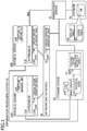
- FIG. 1 is a diagram illustrating a configuration of an information processing system 10 .
- FIG. 2 is a diagram illustrating a hardware configuration of the physical server 20 .
- FIG. 3 is a diagram illustrating a hardware configuration of the management server 50 .
- FIG. 4 is a diagram for describing a major function of the management server 50 .
- FIG. 5 illustrates a specific example of the configuration definition information.
- FIG. 6 illustrates a specific example of the master table.
- FIG. 7 illustrates a specific example of the work table.
- FIG. 8 illustrates a specific example of the command generated by the management server 50 .
- FIG. 9 illustrates a specific example of the command generated by the management server 50 .
- FIG. 10 illustrates a specific example of the command generated by the management server 50 .
- FIG. 11 is a flowchart for describing Operation Example 1 (virtual server creation process) of the management server 50 .
- FIG. 12 is a flowchart for describing Operation Example 1 (virtual server creation process) of the management server 50 .
- FIG. 13 is a flowchart for describing Operation Example 1 (virtual server creation process) of the management server 50 .
- FIG. 14 is a sequence diagram for describing Operation Example 1 of the information processing system 10 .
- FIG. 15 is a sequence diagram for describing Operation Example 1 of the information processing system 10 .
- FIG. 16 is a sequence diagram for describing Operation Example 1 of the information processing system 10 .
- FIG. 17 is a sequence diagram for describing Operation Example 1 of the information processing system 10 .
- FIG. 18 illustrates a state in which the virtual server 22 A (the virtual server name: Dom0001) and the virtual server 22 B (the virtual server name: Dom0002) are not generated in the physical server 20 A (the physical server name: HW001) and the physical server 20 B (the physical server name: HW002), respectively, and an environment for connecting the virtual servers 22 A and 22 B in common to the storage device 40 (the volume name: vd-1101) is not constructed.
- FIG. 19 illustrates a state in which a volume (volume name: vd-1101) is created in the state illustrated in FIG. 18 .
- FIG. 20 illustrates a state in which the LUN group (LUN group name: Dom0001 and Dom0002) is created (the connection with the physical server 20 is configured) in the state illustrated in FIG. 19 .
- FIG. 21 illustrates a state in which a VLAN (VLAN name: 1101) is created (the connection with the physical server 20 is configured) in the state illustrated in FIG. 20 .
- VLAN name: 1101 the connection with the physical server 20 is configured
- FIG. 22 illustrates a state in which the virtual server 22 (the virtual CPU, the memory, the virtual disk, the virtual network, and the like) is created in the state illustrated in FIG. 21 .
- the virtual server 22 the virtual CPU, the memory, the virtual disk, the virtual network, and the like
- FIG. 23 illustrates a specific example of such as a virtual server definition table.
- FIG. 24 illustrates a specific example of the configuration definition information used in Operation Example 2.
- FIG. 25 illustrates a specific example of the master table used in Operation Example 2.
- FIG. 26 illustrates a specific example of the work table used in Operation Example 2.
- FIG. 27 illustrates a specific example of the command generated by the management server 50 in Operation Example 2.
- FIG. 28 illustrates a specific example of the command generated by the management server 50 in Operation Example 2.
- FIG. 29 illustrates a specific example of the command generated by the management server 50 in Operation Example 2.
- FIG. 30 is a flowchart for describing Operation Example 2 (a virtual server removal process) of the management server 50 .
- FIG. 31 is a flowchart for describing Operation Example 2 (a virtual server removal process) of the management server 50 .
- FIG. 32 is a flowchart for describing Operation Example 2 (a virtual server removal process) of the management server 50 .
- FIG. 33 is a sequence diagram for describing Operation Example 2 of the information processing system 10 .
- FIG. 34 is a sequence diagram for describing Operation Example 2 of the information processing system 10 .
- FIG. 35 is a sequence diagram for describing Operation Example 2 of the information processing system 10 .
- FIG. 36 is a specific example of the configuration definition information used in Operation Example 3.
- FIG. 37 illustrates a specific example of the master table used in Operation Example 3.
- FIG. 38 illustrates a specific example of the work table used in Operation Example 3.
- FIG. 39 is a flowchart for describing Operation Example 3 (a virtual server moving process) of the management server 50 .
- FIG. 40 is a flowchart for describing Operation Example 3 (a virtual server moving process) of the management server 50 .
- FIG. 41 is a flowchart for describing Operation Example 3 (a virtual server moving process) of the management server 50 .
- FIG. 42 is a flowchart for describing Operation Example 3 (a virtual server moving process) of the management server 50 .
- FIG. 43 is a flowchart for describing Operation Example 3 (a virtual server moving process) of the management server 50 .
- FIG. 44 is a sequence diagram for describing Operation Example 3 of the information processing system 10 .
- FIG. 45 is a sequence diagram for describing Operation Example 3 of the information processing system 10 .
- FIG. 46 is a sequence diagram for describing Operation Example 3 of the information processing system 10 .
- FIG. 47 is a sequence diagram for describing Operation Example 3 of the information processing system 10 .
- FIG. 48 is a sequence diagram for describing Operation Example 3 of the information processing system 10 .
- FIG. 49 illustrates a state in which the virtual server 22 A (the virtual server name: Dom0001) and the virtual server 22 B (the virtual server name: Dom0002) are generated in the physical server 20 A (the physical server name: HW001) and the physical server 20 B (the physical server name: HW002), respectively, and an environment for connecting the virtual servers 22 A and 22 B in common to the storage device 40 (the volume name: vd-1101) is constructed.
- FIG. 50 illustrates a state in which the virtual server 22 B (the virtual server name: Dom0002) is removed in the state illustrated in FIG. 49 .
- FIG. 51 illustrates a state in which the virtual server 22 B (the virtual server name: Dom0002) is created in the state illustrated in FIG. 50 .
- FIG. 1 is a diagram illustrating a configuration of an information processing system 10 .
- the information processing system 10 illustrated in FIG. 1 includes a plurality of electronic devices and a management device (hereinafter referred to as a management server 50 ).
- the plurality of electronic devices include a plurality of information processing devices (hereinafter referred to as physical servers 20 A and 20 B) that execute virtual servers, a storage device 40 that can be shared by the physical servers 20 A and 20 B, and a communication device (hereinafter referred to as a network switch device 30 ) that can connect to the physical servers 20 A and 20 B.
- a physical server name of the physical server 20 A is HW001
- a physical server name of the physical server 20 B is HW002
- a storage device name of the storage device 40 is ET200-1
- a switch name of the network switch device 30 is Nex2.
- the information processing system 10 may have three or more physical servers.
- the physical servers and the storage device 40 may be connected directly, and although not illustrated in the drawings, they may be connected via an FC switch or a network switch (for example, iSCSI). In this way, a larger number of physical servers can be connected to the storage device 40 .
- the information processing system 10 may have two or more storage devices.
- the information processing system 10 may have two or more network switch devices.
- a high-speed communication network switch device and a low-speed communication network switch device may be connected to a network NW.
- the physical servers 20 A and 20 B, the storage device 40 , the network switch device 30 , and the management server 50 are connected to a network NW such as a LAN and can communicate with each other via the network NW. Although not illustrated in FIG. 1 , actually, the physical server 20 A and the management server 50 are connected by the network NW.
- the physical servers 20 A and 20 B operate hypervisors 21 A and 21 B (dedicated software for generating a virtualization environment) on hardware, respectively. At least one set of virtual servers 22 A and 22 B are generated by the hypervisors 21 A and 21 B, respectively.
- a virtual server name of the virtual server 22 A is Dom0001
- a virtual server name of the virtual server 22 B is Dom0002.
- the physical server is also referred to as a physical machine.
- the virtual server is also referred to as a virtual machine.
- the virtual servers 22 A and 22 B are virtual hardware generated by the hypervisors 21 A and 21 B, respectively, and can operate an OS (guest OS) and an application program on the virtual servers 22 A and 22 B, respectively, similarly to ordinary hardware. Since the virtual servers 22 A and 22 B are separated from the physical servers 20 A and 20 B serving as bases by the hypervisors 21 A and 21 B, it is possible to allocate resources such as a CPU, a memory, a storage, a network, and the like dynamically and flexibly.
- the physical servers 20 A and 20 B, the storage device 40 , and the network switch device 30 have processing units 23 A, 23 B, 43 , and 31 (hereinafter referred to as SVPs 23 A, 23 B, 43 , and 31 ), respectively.
- the SVP is an abbreviation of a service processor.
- the hypervisors 21 A and 21 B (or the SVPs 23 A and 23 B), the SVP 43 , and the SVP 31 change the configurations of devices that include the SVPs, for example, on the basis of control information (hereinafter referred to as commands) received from the management server 50 .
- the physical servers 20 A and 20 B will be referred to as a physical server 20 when the physical servers are not distinguished particularly.
- the hypervisors 21 A and 21 B will be referred to as a hypervisor 21 when the hypervisors are not distinguished particularly.
- the virtual servers 22 A and 22 B will be referred to as a virtual server 22 when the virtual servers are not distinguished particularly.
- the SVPs 23 A and 23 B will be referred to as an SVP 23 when the SVPs are not distinguished particularly.
- the management server 50 includes a master table MT and a work table WT.
- the master table MT and the work table WT are stored in a storage unit (hereinafter referred to as a database 56 ) connected to the management server 50 , for example.
- the database 56 may be stored in a storage 53 (see FIG. 3 ) included in the management server 50 .
- Information indicating a present configuration (a logical configuration) of the information processing system 10 is registered in the master table MT.
- Information (configuration definition information) for changing a present configuration (a logical configuration) of the information processing system 10 is registered in the work table WT.
- the management server 50 generates a command (control information or a control file) that the physical server 20 (the hypervisor 21 or the SVP 23 ), the storage device 40 (the SVP 43 ), and the network switch device 30 (the SVP 31 ) execute on the basis of difference information which is a difference between the master table MT and the work table WT.
- the command is generated in the format of a file (a control file), for example.
- the management server 50 transmits the generated command to the physical server 20 , the storage device 40 , and the network switch device 30 via the network NW.
- the physical server 20 , the storage device 40 , and the network switch device 30 receive the command transmitted from the management server 50 via the network NW.
- the physical server 20 A Upon receiving the command transmitted from the management server 50 via the network NW, the physical server 20 A (the hypervisor 21 or the SVP 23 A) rejisters the data in a virtual server definition table T1A stored in a memory included in the SVP 23 A. Moreover, the physical server 20 A (the hypervisor 21 A or the SVP 23 A) executes the received command. Similarly, upon receiving the command transmitted from the management server 50 via the network NW, the physical server 20 B (the hypervisor 21 B or the SVP 23 B) rejisters the data in a virtual server definition table T1B stored in a memory (not illustrated) included in the SVP 23 B. Moreover, the physical server 20 B (the hypervisor 21 B or the SVP 23 B) executes the received command.
- the virtual server definition tables T1A and T1B will be referred to as a virtual server definition table T1 when the virtual server definition tables are not distinguished particularly.
- the command transmitted from the management server 50 may be received by the SVP 23 of the physical server 20 and may be received by a network interface circuit 20 d (see FIG. 2 ) different from the SVP 23 .
- the received command may be executed by the SVP 23 of the physical server 20 and may be executed by the hypervisor 21 , for example, different from the SVP 23 .
- the command transmitted from the management server 50 is received by the network interface circuit 20 d , and the received command is executed by the hypervisor 21 .
- the storage device 40 upon receiving the command transmitted from the management server 50 via the network NW, the storage device 40 (the SVP 43 ) registers the data in a disk-and-server connection definition table T2 stored in a memory (not illustrated) included in the SVP 43 . Moreover, the storage device 40 (the SVP 43 ) executes the received command.
- the network switch device 30 Upon receiving the command transmitted from the management server 50 via the network NW, the network switch device 30 (the SVP 31 ) registers the data in a virtual network definition table T3 stored in a memory (not illustrated) included in the SVP 31 . Moreover, the network switch device 30 (the SVP 31 ) executes the received command.
- the data is stored in the virtual server definition table T1, the disk-and-server connection definition table T2, and the virtual network definition table T3 and the physical server 20 (the hypervisor 21 ), the storage device 40 (the SVP 43 ), and the network switch device 30 (the SVP 31 ) execute the command transmitted from the management server 50 .
- the virtual server definition table T1 the disk-and-server connection definition table T2
- the virtual network definition table T3 and the physical server 20 the hypervisor 21
- the storage device 40 the SVP 43
- the network switch device 30 the SVP 31
- FIG. 2 is a diagram illustrating a hardware configuration of the physical server 20 .
- the physical server 20 is a desktop computer, a laptop computer, or a server computer, for example.
- the physical server 20 includes a CPU 20 a , an input/output device interface circuit 20 b , a memory 20 c , a network interface circuit 20 d , a storage 20 e , and the SVP 23 .
- the CPU 20 a accesses interface circuits such as the memory 20 c and the input/output device interface circuit 20 b via an internal bus 20 f .
- the CPU 20 a is an electronic component of a processor such as a central processing unit (CPU) and a microprocessing unit (MPU).
- the CPU 20 a may be provided solely or plurally.
- the CPU 20 a reads a program and data stored in the storage 20 e into the memory 20 c to execute program processing related to a virtualization environment and an application program and the like executed by the virtual server 22 .
- the input/output device interface circuit 20 b is a circuit for controlling input and output to and from a peripheral device including devices such as a mouse or a keyboard (not illustrated).
- the memory 20 c is a storage device such as a random access memory (RAM).
- the memory 20 c may be provided solely or plurally.
- the network interface circuit 20 d is an interface circuit for performing communication with other devices (the management server 50 and the like) via the network NW and is a network interface card (NIC), for example.
- the network interface circuit 20 d (hereinafter also referred to a NIC 20 d ) receives a command transmitted from the management server 50 via the network NW.
- the hypervisor 21 executes a process of causing the SVP 23 to register the data in the virtual server definition table T1 stored in the memory (not illustrated) included in the SVP 23 and a process of executing the command received from the management server 50 .
- An OS and an application program executed by the physical server 20 , and data and the like used by the application program are stored in the storage 20 e.
- the SVP 23 includes a CPU, a memory such as a RAM, a NIC, and the like although not illustrated in the drawings.
- a program and data used for the processing of the SVP 23 and the virtual server definition table T1 are stored in the memory included in the SVP 23 .
- the SVP 23 is an independent system separated from the CPU 20 a allocated to the virtual server 22 and performs management of the physical server 20 itself.
- the SVP 23 has a network interface circuit (NIC) separated from the network interface circuit 20 d of the physical server 20 .
- the SVP 23 communicates with other devices (the management server 50 and the like) via the network NW.
- the SVP 23 executes a process of registering the data in the virtual server definition table T1 stored in the memory included in the SVP 23 according to the control from the hypervisor 21 .
- the network switch device 30 is a layer-2 switch, for example, and includes the SVP 31 and the like as illustrated in FIG. 1 .
- the SVP 31 is a device for managing the network switch device 30 and includes a CPU, a memory such as a RAM, a NIC, and the like although not illustrated in the drawings.
- a program and data used for the processing of the SVP 31 and the virtual network definition table T3 are stored in the memory included in the SVP 31 .
- the SVP 31 communicates with other devices (the management server 50 and the like) via the network NW.
- the SVP 31 executes a process of receiving the command transmitted from the management server 50 via the network NW, a process of registering the data in the virtual network definition table T3 stored in the memory included in the SVP 31 , and a process of executing the command received from the management server 50 .
- the storage device 40 includes a plurality of physical disks 42 divided into redundant arrays of inexpensive disks (RAID) groups 41 , the SVP 43 , and the like.
- the physical disk 42 may be a rotating disk and may be a solid disk.
- a logical unit number (LUN) 44 is a volume identifier.
- a physical storage space is dynamically allocated to the LUN 44 .
- the SVP 43 is a device for managing the storage device 40 and includes a CPU, a memory such as a RAM, a NIC, and the like although not illustrated in the drawings.
- a program and data used for processing of the SVP 43 and the disk-and-server connection definition table T2 are stored in the memory included in the SVP 43 .
- the SVP 43 communicates with other devices (the management server 50 and the like) via the network NW.
- the SVP 43 executes a process of receiving the command transmitted from the management server 50 via the network NW, a process of registering the data in the disk-and-server connection definition table T2 stored in the memory included in the SVP 43 , and a process of executing the command received from the management server 50 to create a volume.
- FIG. 3 is a diagram illustrating a hardware configuration of the management server 50 .
- the management server 50 includes a CPU 51 , a memory 52 , a storage 53 , an I/O unit 54 (an external interface), a network interface circuit 55 , and a database 56 .
- the respective units are connected to each other via a bus 61 .
- the CPU 51 executes a predetermined program read from the storage 53 into the memory 52 to thereby realize an input processing unit 57 , a command generation processing unit 58 , a direct control unit 59 , a collecting unit 60 , and the like as illustrated in FIG. 4 .
- the memory 52 is a storage device such as a RAM.
- An OS and an application program executed by the management server 50 and data and the like used by the application program are stored in the storage 53 .
- the I/O unit 54 communicates with the database 56 , for example.
- the network interface circuit 55 is an interface circuit for communicating with other devices (the physical server 20 and the like) via the network NW and is a NIC, for example.
- FIG. 4 is a diagram for describing a major function of the management server 50 .
- the management server 50 includes the input processing unit 57 , the command generation processing unit 58 , the direct control unit 59 , the collecting unit 60 , the database 56 , and the like. These respective functions are realized by the management server 50 (the CPU 51 ) executing a predetermined program read from the storage 53 into the memory 52 .
- “configuration information” indicates the content of the work table WT that the collecting unit 60 transmits to the command generation processing unit 58
- “status information” indicates the content of the master table MT that the collecting unit 60 transmits to the command generation processing unit 58 .
- the input processing unit 57 mainly executes a process of receiving (acquiring) pieces of configuration definition information D1 to D3 input by a user.
- the command generation processing unit 58 mainly executes a process of comparing the work table WT and the master table MT to extract difference information which is a difference between the work table WT and the master table MT and a process of generating the commands to be executed by the physical server 20 (the hypervisor 21 ), the storage device 40 (the SVP 43 ), and the network switch device 30 (the SVP 31 ) on the basis of the extracted difference information.
- the command generation processing unit 58 corresponds to a control information generating unit of the present invention.
- the command generation processing unit 58 may generate a command (for example, i1 to i10) for causing the physical servers 20 A and 20 B to be connected in common to the storage device 40 .
- the command generation processing unit 58 may generate control information (for example, i11 to i19 to be described later) for cancelling the sharing state of the storage device 40 to which the physical servers 20 A and 20 B are connected in common.
- This command may be generated according to a determination result obtained by the command generation processing unit 58 (or the direct control unit 59 ) determining whether the physical servers 20 A and 20 B share the storage device 40 on the basis of the extracted difference information.
- the command generation processing unit 58 may generate a command (for example, i1 to i10) for causing the physical servers 20 A and 20 B to be connected via a virtual switch allocated to the network switch device 30 .
- This command may be generated according to a determination result obtained by the command generation processing unit 58 (or the direct control unit 59 ) determining whether the physical servers 20 A and 20 B are to be connected via the network switch device 30 on the basis of the extracted difference information.
- the direct control unit 59 mainly executes a process of transmitting the command generated by the command generation processing unit 58 to the physical server 20 , the storage device 40 , and the network switch device 30 via the network NW.
- the direct control unit 59 corresponds to a control unit of the present invention.
- the collecting unit 60 mainly executes a process of reading the contents of the work table WT and the master table MT from the database 56 .
- the collecting unit 60 may collect present configuration information of the information processing system 10 from a plurality of electronic devices (the physical server 20 , the storage device 40 , and the network switch device 30 ).
- first configuration definition information (the master table MT) indicating a present configuration of the information processing system 10 may be registered in the database 56 on the basis of the configuration information collected by the collecting unit 60 .
- second configuration definition information (the work table WT) indicating an input-configuration after the change of the information processing system 10 may be registered in the database 56 .
- the work table WT and the master table MT are mainly stored in the database 56 .
- FIG. 4 The details of the respective functions illustrated in FIG. 4 will be described later (see FIGS. 11 to 17 ).
- FIG. 5 illustrates a specific example of the configuration definition information.
- the configuration definition information illustrated in FIG. 5 is information for generating the virtual server 22 A (the virtual server name: Dom0001) and the virtual server 22 B (the virtual server name: Dom0002) in the physical server 20 A (the physical server name: HW001) and the physical server 20 B (the physical server name: HW002), respectively, and constructing an environment for connecting the virtual server 22 A and 22 B in common to the storage device 40 (the volume name: vd-1101).
- the configuration definition information includes server configuration definition information D1, network configuration definition information D2, and storage configuration definition information D3.
- the pieces of configuration definition information D1 to D3 include a correlation between the virtual servers 22 A and 22 B and the physical servers 20 A and 20 B, a correlation between the virtual servers 22 A and 22 B and the storage device 40 , and a correlation between the virtual servers 22 A and 22 B and the network switch device 30 .
- the server configuration definition information D1 includes items such as “user”, “virtual server”, “virtual disk”, and “virtual network”.
- the “user” includes items such as “user name” and “user ID”.
- a user name like “AA corporation” is set in the “user name”.
- Identification information for identifying a user like “0001” is set in the “user ID”.
- the server configuration definition information D1 when a cluster system including two virtual servers 22 A and 22 B is configured, the server configuration definition information D1 includes two rows of server configuration definition information correlated with a “user name” (for example, “AA corporation”).
- the server configuration definition information D1 includes three rows of server configuration definition information correlated with a “user name”. The same is true for the network configuration definition information D2 and the storage configuration definition information D3.
- the “virtual server” includes items such as “status”, “host name”, “virtual server name”, “physical server name”, “cluster group”, “type”, “server type”, and “OS_type”.
- a content (for example, “new” or “operating”) indicating an operating state of a virtual server indicated by “virtual server name” is set in the “status”.
- a host name like “AAA” is set in the “host name”.
- a virtual server name like “Dom0001” is set in the “virtual server name”.
- the name of the physical server 20 like “HW001” is set in the “physical server name”. “A” or “B”, for example, is set in the “cluster group”.
- the content (part or all of the content) of a row immediately above a row that contains the “A” is copied to the row.
- “redundant” or “single” is set in the “type”.
- the “type” in a master table MT8 (see FIG. 6 ) is set in the “server type”.
- the type of an OS that operates on the virtual server 22 is stored in the “OS_type”.
- the “virtual disk” includes items such as “ID”, “Disk name”, and “Disk_type”. Identification information of a virtual disk like “1101” is set in the “ID”. A virtual disk name like “vd-1101” is set in the “Disk name”. “shared” or “single” is set in the “Disk_type”. For example, when “shared” is set, the content (part or all of the content) of a row immediately above a row that contains the “shared” is copied to the row.
- the “virtual network” includes items such as “Port”, “virtual network switch name”, and “VLAN”.
- the port of a virtual network like “Vnet001” is set in the “Port”.
- a virtual network switch name like “vNex2” is set in the “virtual network switch name”.
- An identification number of VLAN like “1101” is set in the “VLAN”.
- the network configuration definition information D2 includes items such as “user”, “status”, “network switch device name”, “Port”, “connection destination server”, “Type”, and “VLAN”.
- the “user” includes items such as “user name” and “user ID”.
- the same contents as those of the server configuration definition information D1 are set in the “user name”, the “user ID”, and the “status”.
- the name of the network switch device 30 like “Nex2” is set in the “network switch device name”.
- a port number of the network switch device 30 is set in the “Port”.
- a physical server name of a connection destination like “HW001” is set in the “connection destination server”.
- the type (Tag or Port) of the “Port” is set in the “Type”.
- An identification number of VLAN like “1101” is set in the “VLAN”.
- the storage configuration definition information D3 includes items such as “user”, “status”, “storage device name”, “LUN”, and “volume”.
- the “user” includes items such as “user name” and “user ID”.
- the same contents as those of the server configuration definition information D1 are set in the “user name”, the “user ID”, and the “status”.
- the name of the storage device 40 like “ET200-1” is set in the “storage device name”.
- the “LUN” includes items such as “LUN group” and “Lun number”.
- the same content as the “virtual server name” in the server configuration definition information D1 like “Dom0001” is set in the “LUN group”.
- a LUN number like “1101” is set in the “Lun number”.
- the “volume” includes items such as “RAID group”, “Vol number”, “Vol name”, and “size”.
- a RAID group like “RG #020” is set in the “RAID group”.
- a Vol number like “1101” is set in the “Vol number”.
- a Vol name (volume name) like “vd-1101” is set in the “Vol name”.
- the size of a volume like “1 TB” is set in the “size”.
- FIG. 6 illustrates a specific example of the master table.
- the master table MT corresponds to first configuration definition information of the present invention.
- the contents illustrated in FIG. 6 are registered in the master table MT as information indicating the present configuration (a logical configuration) of the information processing system 10 .
- the master table MT includes a user table MT1, a virtual server table MT2, a virtual disk table MT3, a virtual network table MT4, a LUN table MT5, a network configuration definition table MT6, a volume table MT7, and a machine type table MT8. Since the respective items in the master tables MTs (MT1 to MT7) are the same as the respective items in the respective pieces of configuration definition information D1 to D3, the description thereof will be omitted.
- FIG. 7 illustrates a specific example of the work table.
- the work table WT corresponds to second configuration definition information of the present invention.
- information for generating the virtual server 22 A (the virtual server name: Dom0001) and the virtual server 22 B (the virtual server name: Dom0002) in the physical server 20 A (the physical server name: HW001) and the physical server 20 B (the physical server name: HW002), respectively, and constructing an environment for connecting the virtual servers 22 A and 22 B in common to the storage device 40 (the volume name: vd-1101) is registered in the work table WT as information for changing the present configuration (a logical configuration) of the information processing system 10 .
- the work table WT includes a user table WT1, a virtual server table WT2, a virtual disk table WT3, a virtual network table WT4, a LUN table WT5, a network configuration definition table WT6, and a volume table WT7.
- the work tables WTs (WT1 to WT7) are obtained by dividing the respective pieces of configuration definition information D1 to D3 illustrated in FIG. 5 for respective categories such as a virtual server, a virtual storage, a virtual network, a network, and a storage. Since the respective items in the work tables WTs (WT1 to WT7) are the same as the respective items in the respective pieces of configuration definition information D1 to D3, the description thereof will be omitted.
- FIGS. 8 to 10 illustrate a specific example of the command generated by the management server 50 .
- the command generated by the management server 50 mainly includes commands related to virtual server creation (see FIG. 8 ), commands related to volume creation (see FIG. 9 ), and commands related to VLAN creation (see FIG. 10 ).
- the commands related to virtual server creation include a virtual server creation command i1, a CPU addition command i2, a Memory addition command i3, a virtual disk addition command i4, a virtual network addition command i5, and a multipath driver addition command i6.
- the commands related to virtual server creation i1 to i6 are transmitted from the management server 50 to the physical servers 20 A and 20 B via the network NW.
- the commands related to volume creation include a volume creation command i7 and a LUN group mapping command i8.
- the commands related to volume creation i7 to i8 are transmitted from the management server 50 to the storage device 40 via the network NW.
- the commands related to VLAN creation include a VLAN creation command i9 and a VLAN addition command i10.
- the commands related to VLAN creation i9 to i10 are transmitted from the management server 50 to the network switch device 30 via the network NW.
- FIGS. 11 to 13 are flowcharts for describing Operation Example 1 (virtual server creation process) of the management server 50 .
- a user deploys the respective pieces of configuration definition information D1 to D3 (see FIG. 5 ) in the management server 50 (step S 11 ). Specifically, the user inputs the respective pieces of configuration definition information D1 to D3 from a terminal (not illustrated) connected to the network NW. The pieces of inputted configuration definition information D1 to D3 are transmitted to the management server 50 via the network NW and the management server 50 (the input processing unit 57 ) receives (acquires) the same.
- the input processing unit 57 extracts the content (row) of which the “status” is “new” from the pieces of configuration definition information D1 to D3 and divides the same for respective categories such as a virtual server, a virtual storage, a virtual network, a network, and a storage (step S 12 ).
- the input processing unit 57 instructs the direct control unit 59 to register the divided pieces of configuration definition information D1 to D3 in the database 56 (the work tables WT1 to WT7) (step S 13 ).
- the direct control unit 59 registers the divided pieces of configuration definition information D1 to D3 in the database 56 (the work tables WT1 to WT7) (step S 14 ). In this way, the contents illustrated in FIG. 7 is registered in the work tables WT1 to WT7.
- the collecting unit 60 reads the contents of the work tables WT1 to WT7 and the master tables MT1 to MT7 from the database 56 and transmits the contents to the command generation processing unit 58 (step S 15 ).
- the command generation processing unit 58 compares the work tables WT1 to WT7 and the master tables MT1 to MT7 (step S 16 ).
- the content of the work tables WT1 to WT7 is included in the master tables MT1 to MT7 (step S 17 : Yes)
- the process ends.
- the command generation processing unit 58 extracts difference information (for example, the information of a volume and a LUN) which is a difference between the work tables WT1 to WT7 and the master tables MT1 to MT7 from the database 56 (the work tables WT1 to WT7) (step S 18 ).
- difference information for example, the information of a volume and a LUN
- the command generation processing unit 58 generates the volume creation command i7 on the basis of the extracted difference information and transmits the volume creation command i7 to the direct control unit 59 (step S 19 ).
- the direct control unit 59 accesses the storage device 40 and executes the volume creation command i7 to create a volume (step S 20 ). Specifically, the direct control unit 59 transmits the volume creation command i7 to the storage device 40 via the network NW. The storage device 40 (the SVP 43 ) receives the volume creation command i7 and executes the same to create a volume.
- step S 21 When a volume creation operation is completed (step S 21 : Yes), the command generation processing unit 58 generates the LUN group mapping command i8 for collaborating the volume with server connection on the basis of the extracted difference information and transmits the LUN group mapping command i8 to the direct control unit 59 (step S 22 ).
- the direct control unit 59 accesses the storage device 40 and executes the LUN group mapping command i8 (step S 23 ). Specifically, the direct control unit 59 transmits the LUN group mapping command i8 to the storage device 40 via the network NW.
- the storage device 40 (the SVP 43 ) receives the LUN group mapping command i8 and executes the same to create a LUN group (configures a connection with the physical server 20 ).
- the management server 50 determines presence of a multipath driver of the physical server 20 (step S 24 ).
- the command generation processing unit 58 generates the multipath driver addition command i6 of the physical server 20 and transmits the same to the direct control unit 59 (step S 25 ).
- the direct control unit 59 accesses the physical server 20 and executes the multipath driver addition command i6 (step S 26 ). Specifically, the direct control unit 59 transmits the multipath driver addition command i6 to the physical server 20 via the network NW.
- the physical server 20 receives the multipath driver addition command i6 (for example, the NIC 20 d receives the command) and executes the same (for example, the hypervisor 21 executes the command) to thereby incorporate an LU into a multipath driver.
- the command generation processing unit 58 extracts difference information (for example, information of a network) which is a difference between the work tables WT1 to WT7 and the master tables MT1 to MT7 from the database 56 (the work tables WT1 to WT7) (step S 27 ).
- difference information for example, information of a network
- the command generation processing unit 58 generates the VLAN creation command i9 and the VLAN addition command i10 of the network port of the network switch device 30 on the basis of the extracted difference information and transmits the commands to the direct control unit 59 (step S 28 ).
- the direct control unit 59 accesses the network switch device 30 and executes the VLAN creation command i9 and the VLAN addition command i10 (step S 29 ). Specifically, the direct control unit 59 transmits the VLAN creation command i9 and the VLAN addition command i10 to the network switch device 30 via the network NW.
- the network switch device 30 (the SVP 31 ) receives the VLAN creation command i9 and the VLAN addition command i10 and executes the commands to thereby add a VLAN.
- the command generation processing unit 58 extracts difference information (for example, information on a virtual server) which is a difference between the work tables WT1 to WT7 and the master tables MT1 to MT7 from the database 56 (the work tables WT1 to WT7) (step S 30 ).
- difference information for example, information on a virtual server
- the command generation processing unit 58 generates the virtual server creation command i1, the CPU addition command i2, the Memory addition command i3, the virtual disk addition command i4, and the virtual network addition command i5 on the basis of the extracted difference information and transmits the commands to the direct control unit 59 (step S 31 ).
- the direct control unit 59 accesses the physical server 20 and executes the virtual server creation command i1, the CPU addition command i2, the Memory addition command i3, the virtual disk addition command i4, and the virtual network addition command i5 (step S 32 ). Specifically, the direct control unit 59 transmits the virtual server creation command i1, the CPU addition command i2, the Memory addition command i3, the virtual disk addition command i4, and the virtual network addition command i5 to the physical server 20 via the network NW.
- the physical server 20 receives the virtual server creation command i1, the CPU addition command i2, the Memory addition command i3, the virtual disk addition command i4, and the virtual network addition command i5 (for example, the NIC 20 d receives the commands) and executes the commands (for example, the hypervisor 21 executes the commands) to thereby create the virtual server 22 .
- step S 33 When creation of all virtual servers 22 is completed (step S 33 : Yes), the command generation processing unit 58 inserts (registers) the contents of the work tables WT1 to WT7 in the master tables MT1 to MT7 (step S 34 ).
- FIGS. 14 to 17 are sequence diagrams for describing Operation Example 1 of the information processing system 10 .
- FIG. 18 a process of generating the virtual server 22 A (the virtual server name: Dom0001) and the virtual server 22 B (the virtual server name: Dom0002) in the physical server 20 A (the physical server name: HW001) and the physical server 20 B (the physical server name: HW002), respectively, from the state illustrated in FIG. 18 , and constructing an environment for connecting the virtual servers 22 A and 22 B in common to the storage device 40 (the volume name: vd-1101) as illustrated in FIG. 22 will be described as Operation Example 1 of the information processing system 10 .
- FIG. 1 Operation Example 1 of the information processing system 10 .
- the virtual server 22 A (the virtual server name: Dom0001) and the virtual server 22 B (the virtual server name: Dom0002) are not generated in the physical server 20 A (the physical server name: HW001) and the physical server 20 B (the physical server name: HW002), respectively, and an environment for connecting the virtual servers 22 A and 22 B in common to the storage device 40 (the volume name: vd-1101) is not constructed.
- a user inputs pieces of configuration definition information D1 to D3 (see FIG. 5 ) (step S 40 ).
- the user inputs the pieces of configuration definition information D1 to D3 from a terminal (not illustrated) or the like connected to the network NW.
- the pieces of configuration definition information D1 to D3 may be input from a keyboard or the like connected to the terminal and may be input by reading a file including the pieces of configuration definition information D1 to D3 into the terminal.
- the pieces of inputted configuration definition information D1 to D3 are transmitted to the management server 50 via the network NW and are received (acquired) by the management server 50 (the input processing unit 57 ).
- the input processing unit 57 divides the pieces of configuration definition information D1 to D3 (step S 41 ). Specifically, the input processing unit 57 extracts a content (row) of which the “status” is “new” from the pieces of configuration definition information D1 to D3 and divides the extracted content corresponding to the “new” for respective categories such as a virtual server, a virtual storage, a virtual network, a network, a storage, and the like.
- the input processing unit 57 instructs the command generation processing unit 58 to generate a command for registering the divided pieces of configuration definition information D1 to D3 in the database 56 (the work tables WT1 to WT7) (step S 42 ).
- the command generation processing unit 58 generates a command for registering the divided pieces of configuration definition information D1 to D3 in the database 56 (the work tables WT1 to WT7) and transmits the command to the direct control unit 59 (step S 43 ).
- the direct control unit 59 reads the divided pieces of configuration definition information D1 to D3 from the input processing unit 57 (step S 44 ).
- the direct control unit 59 registers the read divided pieces of configuration definition information D1 to D3 in the database 56 (the work tables WT1 to WT7) (step S 45 ). In this way, the contents illustrated in FIG. 7 are registered in the work tables WT1 to WT7.
- the collecting unit 60 reads the contents of the work tables WT1 to WT7 and the master tables MT1 to MT7 from the database 56 and transmits the contents to the command generation processing unit 58 (step S 46 ).
- the command generation processing unit 58 compares the work tables WT1 to WT7 and the master tables MT1 to MT7 (step S 47 ).
- the command generation processing unit 58 generates the commands i1 to i10 on the basis of the difference information (in this example, the content of the work tables WT1 to WT7) between the work tables WT1 to WT7 and the master tables MT1 to MT7 (step S 48 ).
- the command generation processing unit 58 generates the commands i1 to i10 in which the difference information (in this example, the content of the work table WT) between the work tables WT1 to WT7 and the master tables MT1 to MT7 is set (applied).
- the difference information in this example, the content of the work table WT
- the master tables MT1 to MT7 is set (applied).
- the command generation processing unit 58 extracts difference information (for example, information of a volume and a LUN) which is a difference between the work tables WT1 to WT7 and the master tables MT1 to MT7 from the database 56 (the work tables WT1 to WT7) and generates the volume creation command i7 on the basis of the extracted difference information.
- difference information for example, information of a volume and a LUN
- volume creation command i7 A specific example of the volume creation command i7 will be described with reference to FIG. 9 .
- the volume creation command i7 includes a character string “ssh” arranged at the start, “ ⁇ management user>”, “ ⁇ storage device name>”, a command “create volume-name”, “ ⁇ volume name>”, “ ⁇ RAID group name>”, “ ⁇ size>”, and “ ⁇ volume number>”.
- a management user name (for example, root) of the storage device 40 is set in the portion “management user”.
- “housing name (ET200-1)” in the volume table WT7 is set in the portion “storage device name”.
- “vol name (vd-1101)” in the volume table WT7 is set in the portion “volume name”.
- “RAID group (RG #020)” in the volume table WT7 is set in the portion “RAID group name”.
- size (1 TB)” in the volume table WT7 is set in the portion “size”.
- “vol number (1101)” in the volume table WT7 is set in the portion “volume number”.
- the following command is generated as the volume creation command i7.
- the command generation processing unit 58 transmits the generated volume creation command i7 to the direct control unit 59 (step S 49 ).
- the direct control unit 59 accesses the storage device 40 and executes the volume creation command i7 (step S 50 ). Specifically, the direct control unit 59 transmits the volume creation command i7 to the storage device 40 using an IP address correlated with the “storage device name (ET200-1)” in the volume creation command i7.
- the IP address can be acquired by referring to a correlation (not illustrated) between the IP address and the “storage device name” retained by the storage 53 of the management server 50 , for example.
- the “storage device name” and the IP address are acquired from the storage device 40 (the SVP 43 ) by the collecting unit 60 , for example, and are stored in the storage 53 of the management server 50 in a correlated state.
- the storage device 40 executes a process of receiving the volume creation command i7 transmitted from the management server 50 via the network NW and a process of registering the data in the disk-and-server connection definition table T2 stored in the memory included in the SVP 43 (step S 51 ).
- the “storage device name (ET200-1)” and the “volume name (vd-1011)” in the volume creation command i7 are registered in the “storage device name” and the “Vol name” in the disk-and-server connection definition table T2 (see FIG. 23 ), respectively.
- a connection state of the disk and the server is registered in the “state” in the disk-and-server connection definition table T2.
- the storage device 40 executes the volume creation command i7 received from the management server 50 to thereby create a volume (volume name: vd-1101) as illustrated in FIG. 19 (step S 52 ).
- FIG. 19 illustrates a state in which a volume (volume name: vd-1101) in the state illustrated in FIG. 18 .
- the storage device 40 (the SVP 43 ) notifies the direct control unit 59 of completion of volume creation (step S 53 ).
- the command generation processing unit 58 generates the LUN group mapping command i8 on the basis of the extracted difference information and transmits the same to the direct control unit 59 (step S 54 ).
- the LUN group mapping command i8 includes a character string “ssh” arranged at the start, “ ⁇ management user>”, “ ⁇ storage device name>”, a command “set lun-group-lg-name”, “ ⁇ LUN group name>”, “ ⁇ volume name>”, and “ ⁇ lun number>”.
- a management user name (for example, root) of the storage device 40 is set in the portion “management user”.
- “storage device name (ET200-1)” in the LUN table WT5 is set in the portion “storage device name”.
- “LUN group name (Dom0001 and Dom0002)” in the LUN table WT5 is set in the portion “LUN group name”.
- “Vol name (vd-1101)” in the LUN table WT5 is set in the portion “volume name”.
- “LUN number (1101)” in the LUN table WT5 is set in the portion “lun number”.
- the direct control unit 59 accesses the storage device 40 and executes the LUN group mapping command i8 (step S 55 ). Specifically, the direct control unit 59 transmits the LUN group mapping command i8 to the storage device 40 using an IP address correlated with the “storage device name (ET200-1)” in the LUN group mapping command i8.
- the storage device 40 executes a process of receiving the LUN group mapping command i8 transmitted from the management server 50 via the network NW and a process of registering the data in the disk-and-server connection definition table T2 stored in the memory included in the SVP 43 (step S 56 ).
- the “LUN group name (Dom0001)” in the LUN group mapping command i8 is registered in “connection server name” in the disk-and-server connection definition table T2 (see FIG. 23 ).
- the storage device 40 executes the LUN group mapping command i8 received from the management server 50 to thereby create a LUN group (LUN group name: Dom0001 and Dom0002) (configure the connection with the physical server 20 ) as illustrated in FIG. 20 (step S 57 ).
- FIG. 20 illustrates a state in which the LUN group (LUN group name: Dom0001 and Dom0002) is created (the connection with the physical server 20 is configured) in the state illustrated in FIG. 19 .
- the command generation processing unit 58 generates commands related to VLAN creation (the VLAN creation command i9 and the VLAN addition command i10) and transmits the commands related to VLAN creation i9 and i10 to the direct control unit 59 (step S 58 ).
- VLAN creation command i9 A specific example of the VLAN creation command i9 will be described with reference to FIG. 10 .
- the VLAN creation command i9 includes a character string “ssh” arranged at the start, “ ⁇ management user>”, “ ⁇ network switch name>”, a command “vlan”, and “ ⁇ VLAN ID>”.
- the management user (for example, root) of the network switch device 30 is set in the portion “management user”.
- switch name (Nex2)” in the network configuration definition table WT6 is set in the portion “network switch name”.
- “VLAN (1101)” in the network configuration definition table WT6 is set in the portion “VLAN ID”.
- the following command is generated as the VLAN creation command i9.
- VLAN addition command i10 A specific example of the VLAN addition command i10 will be described with reference to FIG. 10 .
- the VLAN addition command i10 includes a character string “ssh” arranged at the start, “ ⁇ management user>”, “ ⁇ network switch name>”, a command “interface”, and “ ⁇ port>”. Moreover, the VLAN addition command i10 includes a character string “ssh” arranged at the start, “ ⁇ management user>”, “ ⁇ network switch name>”, a command “switch mode trunk”. Moreover, the VLAN addition command i10 includes a character string “ssh” arranged at the start, “ ⁇ management user>”, “ ⁇ network switch name>”, a command “switch trunk allowed vlan add”, and “ ⁇ VLAN ID>”.
- the management user name (for example, root) of the network switch device 30 is set in the portion “management user”.
- the “switch name (Nex2)” in the network configuration definition table WT6 is set in the portion “network switch name”.
- the “port (010 and 011)” in the network configuration definition table WT6 is set in the portion “port”.
- the “VLAN (1101)” in the network configuration definition table WT6 is set in the portion “VLAN ID”.
- the direct control unit 59 accesses the network switch device 30 and executes commands related to VLAN creation i9 and i10 (step S 59 ). Specifically, the direct control unit 59 transmits the commands related to VLAN creation i9 and i10 to the network switch device 30 using an IP address correlated with the “network switch name (Nex2)” in the commands related to VLAN creation i9 and i10.
- the IP address can be acquired by referring to a correlation (not illustrated) between the IP address and the “network switch name” retained by the storage 53 of the management server 50 , for example.
- the “network switch name” and the IP address are acquired from the network switch device 30 (the SVP 31 ) by the collecting unit 60 , for example, and are stored in the storage 53 of the management server 50 in a correlated state.
- the network switch device 30 executes a process of receiving the commands related to VLAN creation i9 and i10 transmitted from the management server 50 via the network NW and a process of registering the data in the virtual network definition table T3 stored in the memory included in the SVP 31 (step S 60 ).
- “port (010 and 011)” and “VLAN ID (1101)” in the commands related to VLAN creation i9 and i10 are registered in “Port” and “VLAN” in the virtual network definition table T3 (see FIG. 23 ), respectively.
- “Tag” is registered in the “Type” in the virtual network definition table T3 (see FIG. 23 ) when the VLAN addition command i10 contains a command “trunk (meaning of tag)”.
- the state of the virtual network is registered in the “state” in the virtual network definition table T3.
- the network switch device 30 executes the commands related to VLAN creation i9 and i10 received from the management server 50 to thereby create a VLAN (VLAN name: 1101) (configure the connection with the physical server 20 ) as illustrated in FIG. 21 (step S 61 ).
- FIG. 21 illustrates a state in which a VLAN (VLAN name: 1101) is created (the connection with the physical server 20 is configured) in the state illustrated in FIG. 20 .
- the command generation processing unit 58 generates the multipath driver addition command i6 of the physical server 20 and transmits the command to the direct control unit 59 (step S 62 ).
- the multipath driver addition command i6 includes a character string “ssh” arranged at the start, “ ⁇ management user>”, “ ⁇ physical server name>”, and a command “grmpdautoconf”.
- the management user name (for example, root) of the physical server 20 is set in the portion “management user”.
- the “physical server name (HW001 and HW002)” in the virtual server table WT2 is set in the portion “physical server name”.
- the direct control unit 59 accesses the physical server 20 and executes the multipath driver addition command i6 (step S 63 ). Specifically, the direct control unit 59 transmits the multipath driver addition command i6 to the physical server 20 using an IP address correlated with the “physical server name (HW001 and HW002)” in the multipath driver addition command i6.
- the “physical server name” and the IP address are acquired from the physical server 20 (for example, the NIC 20 d ) by the collecting unit 60 , for example, and are stored in the storage 53 of the management server 50 in a correlated state.
- the physical server 20 executes a process of receiving the multipath driver addition command i6 from the management server 50 via the network NW (for example, the NIC 20 d receives the command) and a process of registering the data in the virtual server definition table T1 stored in the memory (not illustrated) included in the SVP 23 (for example, the hypervisor 21 causes the SVP 23 to register the data) (step S 64 ).
- the multipath driver is present in the physical server 20
- “present” is registered in the “multipath” in the virtual server definition table T1 (see FIG. 23 ).
- the physical server 20 executes the multipath driver addition command i6 received from the management server 50 (for example, the hypervisor 21 executes the command) to thereby incorporate an LU into the multipath driver (step S 65 ).
- the command generation processing unit 58 generates commands related to virtual server creation (the virtual server creation command i1, the CPU addition command i2, the Memory addition command i3, the virtual disk addition command i4, and the virtual network addition command i5) and transmits the commands related to virtual server creation i1 to i5 to the direct control unit 59 (step S 66 ).
- the virtual server creation command i1 includes a character string “ssh” arranged at the start, “ ⁇ management user>”, “ ⁇ physical server name>”, a command “Idm add-domain”, and a “ ⁇ virtual server name>”.
- the management user name (for example, root) of the physical server 20 is set in the portion “management user”.
- the “physical server name (HW001 and HW002)” in the virtual server table WT2 is set in the portion “physical server name”.
- the “virtual server name (Dom0001 and Dom0002)” in the virtual server table WT2 is set in the portion “virtual server name”.
- the CPU addition command i2 includes a character string “ssh” arranged at the start, “ ⁇ management user>”, “ ⁇ physical server name>”, a command “Idm set-core”, “ ⁇ number of cores>”, and “ ⁇ virtual server name>”.
- the management user name (for example, root) of the physical server 20 is set in the portion “management user”.
- the “physical server name (HW001 and HW002)” in the virtual server table WT2 is set in the portion “physical server name”.
- the “number of CPUs” in the machine type table MT8 corresponding to the “type” the same as the “machine type” in the virtual server table WT2 is set in the portion “number of cores”. For example, as illustrated in FIG.
- the “number of CPUs (in this example, 4)” in the machine type table MT8 corresponding to the “type (in this example, 2)” the same as the “machine type (in this example, 2)” in the virtual server table WT2 is set in the “number of cores”.
- the “virtual server name (Dom0001 and Dom0002)” in the virtual server table WT2 is set in the portion “virtual server name”.
- the Memory addition command i3 includes a character string “ssh” arranged at the start, “ ⁇ management user>”, “ ⁇ physical server name>”, a command “Idm set-memory”, “ ⁇ capacity>”, and “ ⁇ virtual server name>”.
- the management user name (for example, root)” of the physical server 20 is set in the portion “management user”.
- the “physical server name (HW001 and HW002)” in the virtual server table WT2 is set in the portion “physical server name”.
- the “Memory capacity” in the machine type table MT8 corresponding to the “type” the same as the “machine type” in the virtual server table WT2 is set in the portion “capacity”. For example, as illustrated in FIG.
- the “Memory capacity (in this example, 64 GB)” in the machine type table MT8 corresponding to the “type (in this example, 2)” the same as the “machine type (in this example, 2)” in the virtual server table WT2 is set in the portion “capacity”.
- the “virtual server name (Dom0001 and Dom0002)” in the virtual server table WT2 is set in the portion “virtual server name”.
- the virtual disk addition command i4 includes a character string “ssh” arranged at the start, “ ⁇ management user>”, “ ⁇ physical server name>”, a command “Idm add-vdsdev”, “ ⁇ LUN>”, “ ⁇ virtual disk name>”, and “ ⁇ virtual disk service name>”.
- the virtual disk addition command i4 includes a character string “ssh” arranged at the start, “ ⁇ management user>”, “ ⁇ physical server name>”, a command “Idm add-vdisk”, “ ⁇ virtual disk name>”, “ ⁇ virtual disk service name>”, and “ ⁇ virtual server name>”.
- the management user name (for example, root) of the physical server 20 is set in the portion “management user”.
- the “physical server name (HW001 and HW002)” in the virtual server table WT2 is set in the portion “physical server name”.
- the “Lun number (1101)” in the virtual disk table WT3 is set in the portion “LUN”.
- the “Disk name (vd-1101)” in the virtual disk table WT3 is set in the portion “virtual disk name”.
- a default name is set in the portion “virtual disk service name”.
- the “virtual server name (Dom0001 and Dom0002)” in the virtual disk table WT3 is set in the portion “virtual server name”.
- the management user name (for example, root) of the physical server 20 is set in the portion “management user”.
- the “physical server name (HW001 and HW002)” in the virtual server table WT2 is set in the portion “physical server name”.
- the “VLAN (1101)” in the virtual network table WT4 is set in the portion “VLAN ID”.
- the “port name (Vnet001)” in the virtual network table WT4 is set in the portion “virtual network port name”.
- the “virtual switch name (VNex2)” in the network configuration definition table WT6 is set in the portion “virtual switch name”.
- the “virtual server name (Dom0001 and Dom0002)” in the virtual network table WT4 is set in the portion “virtual server name”.
- the direct control unit 59 accesses the physical server 20 and executes the commands related to virtual server creation i1 to i5 (step S 67 ). Specifically, the direct control unit 59 transmits the commands related to virtual server creation i1 to i5 to the physical server 20 using an IP address correlated with the “physical server name (HM001 and HM002) in the commands related to virtual server creation i1 to i5.
- the IP address can be acquired by referring to a correlation (not illustrated) between the IP address and the “physical server name” retained by the storage 53 of the management server 50 , for example.
- the physical server 20 executes a process of receiving the commands related to virtual server creation i1 to i5 transmitted from the management server 50 via the network NW (for example, the NIC 20 d receives the commands) and a process of registering the data in the virtual server definition table T1 stored in the memory (not illustrated) included in the SVP 23 (for example, the hypervisor 21 causes the SVP 23 to register the data) (step S 68 ).
- the “virtual server name” in the virtual server creation command i1, the “number of cores” in the CPU addition command i2, the “capacity” in the Memory addition command i3, the “virtual disk name” in the virtual disk addition command i4, the “virtual network port name” in the virtual network addition command i5, the “virtual switch name” in the virtual network addition command i5, and the “VLAN ID” in the virtual network addition command i5 are registered in the “virtual server name”, the “number of CPUs”, the “Memory capacity”, the “Disk name”, the “port name”, the “virtual switch name”, and the “VLAN” in the virtual server definition table T1 (see FIG. 23 ), respectively.
- the type of a physical port like “dedicated switch” is registered in the “physical port” in the virtual server definition table T1.
- the state of the virtual server is registered in the “state” in the virtual server definition table T1.
- the physical server 20 executes the commands related to virtual server creation i1 to i5 received from the management server 50 to thereby create the virtual server 22 (a virtual CPU, a memory, a virtual disk, a virtual network, and the like) as illustrated in FIG. 22 (steps S 69 to S 72 ).
- FIG. 22 illustrates a state in which the virtual server 22 (the virtual CPU, the memory, the virtual disk, the virtual network, and the like) is created in the state illustrated in FIG. 21 .
- the physical server 20 (the hypervisor 21 or the SVP 23 ) notifies the direct control unit 59 of completion of creation of the virtual servers (step S 73 ).
- the command generation processing unit 58 accesses the database 56 according to an instruction (step S 74 ) of the direct control unit 59 and inserts the contents of the work tables WT1 to WT7 into the master tables MT1 to MT7 (step S 75 ).
- FIG. 26 illustrates the master tables MTs (MT1A to MT7A) after insertion.
- the creation commands i1 to i10 for virtual servers and the like on the basis of the difference information (for example, the contents of the work tables WT1 to WT7) which is a difference between the work tables WT1 to WT7 and the master tables MT1 to MT7, transmit the generated creation commands i1 to i10 for virtual servers and the like to the physical server 20 (for example, the hypervisor), the network switch device 30 (the SVP 31 ), and the storage device 40 (the SVP 43 ) to generate the virtual servers 22 , and construct an environment for connecting the virtual servers 22 in common to the storage device 40 (the volume).
- the physical server 20 for example, the hypervisor
- the network switch device 30 the SVP 31
- the storage device 40 the SVP 43
- FIG. 24 illustrates a specific example of the configuration definition information used in Operation Example 2.
- the configuration definition information illustrated in FIG. 24 is information for removing the virtual server 22 A (the virtual server name: Dom0001) and the virtual server 22 B (the virtual server name: Dom0002), and removing an environment for connecting the virtual server 22 A and 22 B in common to the storage device 40 (the volume name: vd-1101) in a case in which the virtual server 22 A (the virtual server name: Dom0001) and the virtual server 22 B (the virtual server name: Dom0002) are generated in the physical server 20 A (the physical server name: HW001) and the physical server 20 B (the physical server name: HW002) and an environment for connecting the virtual servers 22 A and 22 B in common to the storage device 40 (the volume name: vd-1101) is constructed as illustrated in FIG. 22 .
- the configuration definition information includes server configuration definition information D4, network configuration definition information D5, and storage configuration definition information D6.
- the pieces of configuration definition information D4 to D6 correspond to information in which “new” of the “status” in the pieces of configuration definition information D1 to D3 is replaced with “removal”. Since the respective items in the pieces of configuration definition information D4 to D6 are the same as the respective items in the pieces of configuration definition information D1 to D3, the description thereof will be omitted.
- FIG. 25 illustrates a specific example of the master table used in Operation Example 2.
- the master table MT includes a user table MT1A, a virtual server table MT2A, a virtual disk table MT3A, a virtual network table MT4A, a LUN table MT5A, a network configuration definition table MT6A, a volume table MT7A, and a machine type table MT8A. Since the respective items in the master tables MTs (MT1A to MT7A) are the same as the respective items in the configuration definition information D4 to D6, the description thereof will be omitted.
- FIG. 26 illustrates a specific example of the work table used in Operation Example 2.
- Information for changing (removing) the present configuration (the logical configuration) of the information processing system 10 is registered in the work table WT.
- the work table WT Information for changing (removing) the present configuration (the logical configuration) of the information processing system 10 is registered in the work table WT.
- information for removing the virtual server 22 A (the virtual server name: Dom0001) and the virtual server 22 B (the virtual server name: Dom0002) and removing an environment for connecting the virtual servers 22 A and 22 B in common to the storage device 40 (the volume name: vd-1101) is registered in the work table WT as information for changing (removing) the present configuration (the logical configuration) of the information processing system 10 .
- the work table WT includes a user table WT1A, a virtual server table WT2A, a virtual disk table WT3A, a virtual network table WT4A, a LUN table WT5A, a network configuration definition table WT6A, and a volume table WT7A.
- the work tables WTs (WT1A to WT7A) are obtained by dividing the pieces of configuration definition information D4 to D6 illustrated in FIG. 24 for respective categories such as a virtual server, a virtual storage, a virtual network, a network, a storage, and the like. Since the respective items of the work tables WTs (WT1A to WT7A) are the same as the respective items of the pieces of configuration definition information D4 to D6, the description thereof will be omitted.
- FIGS. 27 to 29 illustrate specific examples of the commands generated by the management server 50 in Operation Example 2.
- the commands generated by the management server 50 mainly include commands related to virtual server removal (see FIG. 27 ), commands related to volume deletion (see FIG. 28 ), and commands related to VLAN removal (see FIG. 29 ).
- the commands related to virtual server removal include a virtual server stop command i11, a virtual server removal command i12, a virtual disk removal command i13, a virtual network removal command i14, and a multipath driver removal command i15.
- the commands related to virtual server removal i11 to i15 are transmitted from the management server 50 to the physical servers 20 A and 20 B via the network NW.
- the commands related to volume deletion include a volume deletion command i16 and a LUN group mapping cancel command i17.
- the commands related to volume deletion i16 to i17 are transmitted from the management server 50 to the storage device 40 via the network NW.
- the commands related to VLAN removal include a VLAN removal command i18 and a VLAN removal command i19.
- the commands related to VLAN removal i18 to i19 are transmitted from the management server 50 to the network switch device 30 via the network NW.
- FIGS. 30 to 32 are flowcharts for describing Operation Example 2 (a virtual server removal process) of the management server 50 .
- a user deploys the respective pieces of configuration definition information D4 to D6 (see FIG. 24 ) in the management server 50 (step S 81 ). Specifically, the user inputs the respective pieces of configuration definition information D4 to D6 from a terminal (not illustrated) connected to the network NW. The pieces of inputted configuration definition information D4 to D6 are transmitted to the management server 50 via the network NW and the management server 50 (the input processing unit 57 ) receives (acquires) the same.
- the input processing unit 57 extracts the content (row) of which the “status” is “removal” from the pieces of configuration definition information D4 to D6 and divides the same for respective categories such as a virtual server, a virtual storage, a virtual network, a network, and a storage (step S 82 ).
- the input processing unit 57 instructs the direct control unit 59 to register the divided pieces of configuration definition information D4 to D6 in the database 56 (the work tables WT1A to WT7A) (step S 83 ).
- the direct control unit 59 registers the divided pieces of configuration definition information D4 to D6 in the database 56 (the work tables WT1A to WT7A) (step S 84 ). In this way, the contents illustrated in FIG. 26 is registered in the work tables WT1A to WT7A.
- the collecting unit 60 reads the contents of the work tables WT1A to WT7A and the master tables MT1A to MT7A from the database 56 and transmits the contents to the command generation processing unit 58 (step S 85 ).
- the command generation processing unit 58 compares the work tables WT1A to WT7A and the master tables MT1A to MT7A (step S 86 ).
- the content of the work tables WT1A to WT7A is not included in the master tables MT1A to MT7A (step S 87 : No), the process ends.
- the command generation processing unit 58 extracts identical information (for example, the information of a virtual server) between the work tables WT1A to WT7A and the master tables MT1A to MT7A from the database 56 (the work tables WT1A to WT7A) (step S 88 ).
- the command generation processing unit 58 generates the commands related to virtual server removal i11 to i14 (the virtual server stop command i11, the virtual server removal command i12, the virtual disk removal command i13, and the virtual network removal command i14) on the basis of the extracted identical information and transmits the commands to the direct control unit 59 (step S 89 ).
- the direct control unit 59 accesses the physical server 20 and executes the commands related to virtual server removal i11 to i14 (step S 90 ). Specifically, the direct control unit 59 transmits the commands related to virtual server removal i11 to i14 to the physical server 20 via the network NW. The physical server 20 receives the commands related to virtual server removal i11 to i14 and executes the commands to thereby remove the virtual server 22 .
- step S 91 When removal of all virtual servers 22 is completed (step S 91 : Yes), the command generation processing unit 58 extracts identical information (for example, information of a network) between the work tables WT1A to WT7A and the master table MT1A to MT7A from the database 56 (the work tables WT1A to WT7A) (step S 92 ).
- identical information for example, information of a network
- the command generation processing unit 58 generates commands related to VLAN removal i18 to i19 (the VLAN removal command i18 and the VLAN removal command i19) of the network port of the network switch device 30 on the basis of the extracted identical information and transmits the commands to the direct control unit 59 (step S 93 ).
- the direct control unit 59 accesses the network switch device 30 and executes the commands related to VLAN removal i18 to i19 (step S 94 ). Specifically, the direct control unit 59 transmits the commands related to VLAN removal i18 to i19 to the network switch device 30 via the network NW. The network switch device 30 receives the commands related to VLAN removal i18 to i19 and executes the commands to thereby remove the VLAN.
- the command generation processing unit 58 generates the LUN group mapping cancel command i17 on the basis of the identical information between the work tables WT1A to WT7A and the master tables MT1A to MT7A and transmits the command to the direct control unit 59 (step S 95 ).
- the direct control unit 59 accesses the storage device 40 and executes the LUN group mapping cancel command i17 (step S 96 ). Specifically, the direct control unit 59 transmits the LUN group mapping cancel command i17 to the storage device 40 via the network NW. The storage device 40 receives the LUN group mapping cancel command i17 and executes the command to thereby cancel the LUN group mapping.
- the management server 50 determines whether the multipath driver of the physical server 20 is present (step S 97 ).
- the command generation processing unit 58 generates the multipath driver removal command i15 on the basis of the identical information between the work tables WT1A to WT7A and the master tables MT1A to MT7A and transmits the command to the direct control unit 59 (step S 98 ).
- the direct control unit 59 accesses the physical server 20 and executes the multipath driver removal command i15 (step S 99 ). Specifically, the direct control unit 59 transmits the multipath driver removal command i15 to the physical server 20 via the network NW. The physical server 20 receives the multipath driver removal command i15 and executes the command to thereby remove an LU from the multipath driver.
- the command generation processing unit 58 extracts the identical information (for example, information of a volume and a LUN) between the work tables WT1A to WT7A and the master tables MT1A to MT7A from the database 56 (the work tables WT1 to WT7) (step S 100 ), generate the volume deletion command i16 on the basis of the extracted identical information, and transmits the command to the direct control unit 59 (step S 101 ).
- the identical information for example, information of a volume and a LUN
- the direct control unit 59 accesses the storage device 40 and executes the volume deletion command i16 to thereby delete a volume (step S 102 ). Specifically, the direct control unit 59 transmits the volume deletion command i16 to the storage device 40 via the network NW. The storage device 40 receives the volume deletion command i16 and executes the command to thereby delete the volume.
- step S 103 When deletion of the volume is completed (step S 103 : Yes), the command generation processing unit 58 accesses the database 56 and removes the content of the work tables WT1A to WT7A from the master tables MT1A to MT7A (step S 104 ).
- FIGS. 33 to 35 are sequence diagrams for describing Operation Example 2 of the information processing system 10 .
- a user inputs pieces of configuration definition information D4 to D6 (see FIG. 24 ) (step S 110 ).
- the user inputs the pieces of configuration definition information D4 to D6 from a terminal (not illustrated) or the like connected to the network NW.
- the pieces of configuration definition information D4 to D6 may be input from a keyboard or the like connected to the terminal and may be input by reading a file including the pieces of configuration definition information D4 to D6 into the terminal.
- the pieces of inputted configuration definition information D4 to D6 are transmitted from the terminal to the management server 50 via the network NW and are received (acquired) by the management server 50 (the input processing unit 57 ).
- the input processing unit 57 divides the pieces of configuration definition information D4 to D6 (step S 111 ). Specifically, the input processing unit 57 extracts a content of which the “status” is “removal” from the pieces of configuration definition information D4 to D6 and divides the extracted content for respective categories such as a virtual server, a virtual storage, a virtual network, a network, a storage, and the like.
- the input processing unit 57 instructs the command generation processing unit 58 to generate a command for registering the divided pieces of configuration definition information D4 to D6 in the database 56 (the work tables WT1A to WT7A) (step S 112 ).
- the command generation processing unit 58 generates a command for registering the divided pieces of configuration definition information D4 to D6 in the database 56 (the work tables WT1A to WT7A) and transmits the command to the direct control unit 59 (step S 113 ).
- the direct control unit 59 reads the divided pieces of configuration definition information D4 to D6 from the input processing unit 57 (step S 114 ).
- the direct control unit 59 registers the read divided pieces of configuration definition information D4 to D6 in the database 56 (the work tables WT1A to WT7A) (step S 115 ). In this way, the contents illustrated in FIG. 26 are registered in the work tables WT1A to WT7A.
- the collecting unit 60 reads the contents of the work tables WT1A to WT7A and the master tables MT1A to MT7A from the database 56 and transmits the contents to the command generation processing unit 58 (step S 116 ).
- the command generation processing unit 58 compares the work tables WT1A to WT7A and the master tables MT1A to MT7A (step S 117 ).
- the command generation processing unit 58 generates the commands i11 to i19 on the basis of the identical information (in this example, the content of the work tables WT1A to WT7A) between the work tables WT1A to WT7A and the master tables MT1A to MT7A (step S 118 ).
- the command generation processing unit 58 generates the commands i11 to i19 in which the identical information (in this example, the content of the work tables WT1A to WT7A) between the work tables WT1A to WT7A and the master tables MT1A to MT7A is set (applied).
- the identical information in this example, the content of the work tables WT1A to WT7A
- the master tables MT1A to MT7A is set (applied).
- a specific example of the commands i11 to i19 will be described later.
- the command generation processing unit 58 extracts identical information (for example, information of a virtual server) between the work tables WT1A to wt17 and the master tables MT1A to MT7A from the database 56 (the work tables WT1A to WT7A) and generates commands related to virtual server removal (the virtual server stop command i11, the virtual server removal command i12, the virtual disk removal command i13, and the virtual network removal command i14) on the basis of the extracted identical information.
- identical information for example, information of a virtual server
- the command generation processing unit 58 extracts identical information (for example, information of a virtual server) between the work tables WT1A to wt17 and the master tables MT1A to MT7A from the database 56 (the work tables WT1A to WT7A) and generates commands related to virtual server removal (the virtual server stop command i11, the virtual server removal command i12, the virtual disk removal command i13, and the virtual network removal command i14) on the basis of
- the virtual server stop command i11 includes a character string “ssh” arranged at the start, “ ⁇ management user>”, “ ⁇ physical server name>”, a command “Idm stop-domain”, and “ ⁇ virtual server name>”.
- the management user name (for example, root) of the physical server 20 is set in the portion “management user”.
- the “physical server name (HW001 and HW002)” in the virtual server table WT2A is set in the portion “physical server name”.
- the “virtual server name (Dom0001 and Dom0002)” in the virtual server table WT2A is set in the portion “virtual server name”.
- the virtual server removal command i12 includes a character string “ssh” arranged at the start, “ ⁇ management user>”, “ ⁇ physical server name>”, a command “Idm remove-domain”, and “ ⁇ virtual server name>”.
- the management user name (for example, root) of the physical server 20 is set in the portion “management user”.
- the “physical server name (HW001 and HW002)” in the virtual server table WT2A is set in the portion “physical server name”.
- the “virtual server name (Dom0001 and Dom0002)” in the virtual server table WT2A is set in the portion “virtual server name”.
- the virtual disk removal command i13 includes a character string “ssh” arranged at the start, “ ⁇ management user>”, “ ⁇ physical server name>”, a command “Idm remove-vdsdev”, “ ⁇ virtual disk name>”, and “virtual disk service name”.
- the management user name (for example, root) of the physical server 20 is set in the portion “management user”.
- the “physical server name (HW001 and HW002)” in the virtual server table WT2A is set in the portion “physical server name”.
- the “Disk name (vd-1101 and vd-1101)” in the virtual disk table WT3A is set in the portion “virtual disk name”.
- a default name is set in the portion “virtual disk service name”.
- the virtual network removal command i14 includes a character string “ssh” arranged at the start, “ ⁇ management user>”, “ ⁇ physical server name>”, a command “Idm remove-vnet”, “ ⁇ virtual network port name>”, and “ ⁇ virtual server name>”.
- the management user name (for example, root) of the physical server 20 is set in the portion “management user”.
- the “physical server name (HW001 and HW002)” in the virtual server table WT2A is set in the portion “physical server name”.
- the “port name (Vnet001 and Vnet001)” in the virtual network table WT4A is set in the portion “virtual network port name”.
- the “virtual server name (Dom0001 and Dom0002)” in the virtual server table WT2A is set in the portion “virtual server name”.
- the command generation processing unit 58 transmits the commands related to virtual server removal i11 to i14 to the direct control unit 59 (step S 119 ).
- the direct control unit 59 accesses the physical server 20 and executes the commands related to virtual server removal i11 to i14 (step S 120 ). Specifically, the direct control unit 59 transmits the commands related to virtual server removal i11 to i14 to the physical server 20 using an IP address correlated with the “physical server name (HM001 and HM002)” in the commands related to virtual server removal i11 to i14.
- the physical server 20 receives the commands related to virtual server removal i11 to i14 transmitted from the management server 50 via the network NW.
- the physical server 20 executes the commands related to virtual server removal i11 to i14 received from the management server 50 to thereby execute a process (step S 121 ) of stopping the virtual server 22 , a process (step S 122 ) of removing the virtual disk, a process (step S 123 ) of removing the virtual network, and a process (step S 124 ) of removing the virtual server.
- the physical server 20 may execute a process of deleting the virtual server definition table T1 stored in the memory included in the SVP 23 .
- the command generation processing unit 58 generates the commands related to VLAN removal (the VLAN removal command i18 and the VLAN removal command i19) and transmits the commands related to VLAN removal i18 and i19 to the direct control unit 59 (step S 125 ).
- VLAN removal command i18 A specific example of the VLAN removal command i18 will be described with reference to FIG. 29 .
- the VLAN removal command i18 includes a character string “ssh” arranged at the start, “ ⁇ management user>”, “ ⁇ network switch name>”, a command “no vlan”, and “ ⁇ VLAN ID>”.
- the management user name (for example, root) of the network switch device 30 is set in the portion “management user”.
- the “switch name (Nex2)” in the network configuration definition table WT6A is set in the portion “network switch name”.
- the “VLAN (1101)” in the network configuration definition table WT6A is set in the portion “VLAN ID”.
- the following command is generated as the VLAN removal command i18.
- VLAN removal command i19 A specific example of the VLAN removal command i19 will be described with reference to FIG. 29 .
- the VLAN removal command i19 includes a character string “ssh” arranged at the start, “ ⁇ management user>”, “ ⁇ network switch name>”, a command “interface”, and “port”. Moreover, the VLAN removal command i19 includes a character string “ssh” arranged at the start, “ ⁇ management user>”, “ ⁇ network switch name>”, and a command “switch mode trunk”. Moreover, the VLAN removal command i19 includes a character string “ssh” arranged at the start, “ ⁇ management user>”, “ ⁇ network switch name>”, a command “switch trunk allowed vlan remove”, and “ ⁇ VLAN ID>”.
- the management user name (for example, root) of the network switch device 30 is set in the portion “management user”.
- the “switch name (Nex2)” in the network configuration definition table WT6A is set in the portion “network switch name”.
- the “port (010 and 011)” in the network configuration definition table WT6A is set in the portion “port”.
- the “VLAN (1101)” in the network configuration definition table WT6A is set in the portion “VLAN ID”.
- the direct control unit 59 accesses the network switch device 30 and executes the commands related to VLAN removal i18 and i19 (step S 126 ). Specifically, the direct control unit 59 transmits the commands related to VLAN removal i18 and i19 to the network switch device 30 using an IP address correlated with the “network switch name (Nex2)” in the commands related to VLAN removal i18 and i19.
- the network switch device 30 (the SVP 31 ) receives the commands related to VLAN removal i18 and i19 transmitted from the management server 50 via the network NW and executes the commands related to VLAN removal i18 and i19 to thereby remove the VLAN (step S 127 ). Furthermore, the network switch device 30 (the SVP 31 ) may execute a process of deleting the virtual network definition table T3 stored in the memory included in the SVP 31 .
- the command generation processing unit 58 generates the LUN group mapping cancel command i17 and transmits the command to the direct control unit 59 (step S 128 ).
- the LUN group mapping cancel command i17 includes a character string “ssh” arranged at the start, “ ⁇ management user>”, “ ⁇ storage device name>”, a command “delete lun-group-lg-name”, “ ⁇ LUN group name>”, and “lun number”.
- the management user name (for example, root) of the storage device 40 is set in the portion “management user”.
- the “housing name (ET200-1)” in the volume table WT7A is set in the portion “storage device name”.
- the “LUN group name (Dom0001 and Dom0002)” in the LUN table WT5A is set in the portion “LUN group name”.
- the “LUN number (1101)” in the LUN table WT5A is set in the portion “lun number”.
- the direct control unit 59 accesses the storage device 40 and executes the LUN group mapping cancel command i17 (step S 129 ). Specifically, the direct control unit 59 transmits the LUN group mapping cancel command i17 to the storage device 40 using an IP address correlated with the “storage device name (ET200-1)” in the LUN group mapping cancel command i17.
- the storage device 40 (the SVP 43 ) receives the LUN group mapping cancel command i17 transmitted from the management server 50 via the network NW and executes the received LUN group mapping cancel command i17 to thereby cancel the LUN group (step S 130 ). Furthermore, the storage device 40 (the SVP 43 ) may execute a process of deleting the disk-and-server connection definition table T2 stored in the memory included in the SVP 43 .
- the command generation processing unit 58 generates the multipath driver removal command i15 and transmits the command to the direct control unit 59 (step S 130 ).
- the multipath driver removal command i15 includes a character string “ssh” arranged at the start, “ ⁇ management user>”, “ ⁇ physical server name>”, and a command “grmpdautoconf”.
- the management user name (for example, root) of the physical server 20 is set in the portion “management user”.
- the “physical server name (HW001 and HW002)” in the virtual server table WT2A is set in the portion “physical server name”.
- the direct control unit 59 accesses the physical server 20 and executes the multipath driver removal command i15 (step S 131 ). Specifically, the direct control unit 59 transmits the multipath driver removal command i15 to the physical server 20 using an IP address correlated with the “physical server name (HW001 and HW002)” in the multipath driver removal command i15.
- the physical server 20 receives the multipath driver removal command i15 transmitted from the management server 50 via the network NW and executes the received multipath driver removal command i15 to thereby remove the LU from the multipath driver (step S 132 ).
- the command generation processing unit 58 generates the volume deletion command i16 and transmits the command to the direct control unit 59 (step S 133 ).
- volume deletion command i16 A specific example of the volume deletion command i16 will be described with reference to FIG. 28 .
- the volume deletion command i16 includes a character string “ssh” arranged at the start, “ ⁇ management user>”, “ ⁇ storage device name>”, a command “delete volume-volume-number”, and “ ⁇ volume number>”.
- the management user name (for example, root) of the storage device 40 is set in the portion “management user”.
- the “housing name (ET200-1)” in the volume table WT7A is set in the portion “storage device name”.
- the “vol number (1101)” in the volume table WT7A is set in the portion “volume number”.
- the following command is generated as the volume deletion command i16.
- the direct control unit 59 accesses the storage device 40 and executes the volume deletion command i16 (step S 134 ). Specifically, the direct control unit 59 transmits the volume deletion command i16 to the storage device 40 using an IP address correlated with the “storage device name (ET200-1)” in the volume deletion command i16.
- the storage device 40 (the SVP 43 ) receives the volume deletion command i16 transmitted from the management server 50 via the network NW and executes the received volume deletion command i16 to thereby delete the volume (step S 135 ). Furthermore, the storage device 40 (the SVP 43 ) may execute a process of deleting the disk-and-server connection definition table T2 stored in the memory included in the SVP 43 .
- FIG. 36 is a specific example of the configuration definition information used in Operation Example 3.
- the configuration definition information illustrated in FIG. 36 is information for removing the virtual server 22 B (the virtual server name: Dom0002) as illustrated in FIG. 50 , generating the virtual server 22 B (the virtual server name: Dom0002) in a physical server 20 C (the physical server name: HW004) as illustrated in FIG.
- the physical server 20 C is further added to the configuration illustrated in FIG. 1 .
- the configuration definition information includes server configuration definition information D7, network configuration definition information D8, and storage configuration definition information D9.
- the pieces of configuration definition information D7 to D9 correspond to information in which “new” of the “status” in the pieces of configuration definition information D1 to D3 is replaced with “change”, “HW0001” of the “physical server name” in the server configuration definition information D7 is replaced with “HW0004”, “011” of the “Port” in the network configuration definition information D8 is replaced with “013”, “HW0002” of the “connection destination server” in the network configuration definition information D8 is replaced with “HW0004”, and “Dom0002” of the “LUN group” is replaced with “Dom0004”.
- FIG. 37 illustrates a specific example of the master table used in Operation Example 3.
- the master table MT includes a user table MT1B, a virtual server table MT2B, a virtual disk table MT3B, a virtual network table MT4B, a LUN table MT5B, a network configuration definition table MT6B, a volume table MT7B, and a machine type table MT8B. Since the respective items of the master tables MT (MT1B to MT7B) are the same as the respective items in the pieces of configuration definition information D7 to D9, the description thereof will be omitted.
- FIG. 38 illustrates a specific example of the work table used in Operation Example 3.
- Information for changing (deleting) the present configuration (the logical configuration) of the information processing system 10 is registered in the work table WT.
- information for removing the virtual server 22 B (the virtual server name: Dom0002) as illustrated in FIG. 50
- generating the virtual server 22 B (the virtual server name: Dom0002) in the physical server 20 C (the physical server name: HW004) as illustrated in FIG. 51
- removing an environment for connecting the virtual servers 22 A and 22 B in common to the storage device 40 (the volume name: vd-1101) is registered in the work table WT as the information for changing (removing) the present configuration (the logical configuration) of the information processing system 10 .
- the work table WT includes a user table WT1B, a virtual server table WT2B, a virtual disk table WT3B, a virtual network table WT4B, a LUN table WT5B, a network configuration definition table WT6B, and a volume table WT7B.
- the work tables WTs (WT1B to WT7B) are obtained by dividing the pieces of configuration definition information D7 to D9 illustrated in FIG. 36 for respective categories such as a virtual server, a virtual storage, a virtual network, a network, a storage, and the like. Since the respective items of the work tables WTs (WT1B to WT7B) are the same as the respective items in the pieces of configuration definition information D7 to D8, the description thereof will be omitted.
- the commands generated by the management server 50 in Operation Example 3 include the commands i1 to i10 ( FIGS. 8 to 10 ) described in Operation Example 1 and the commands i11 to i19 ( FIGS. 27 to 29 ) described in Operation Example 2.
- FIGS. 39 to 43 are flowcharts for describing Operation Example 3 (a virtual server moving process) of the management server 50 .
- a user deploys the pieces of configuration definition information D7 to D9 (see FIG. 36 ) in the management server 50 (step S 141 ). Specifically, the user inputs the respective pieces of configuration definition information D7 to D9 from a terminal (not illustrated) connected to the network NW. The pieces of inputted configuration definition information D7 to D9 are transmitted to the management server 50 via the network NW and the management server 50 (the input processing unit 57 ) receives (acquires) the same.
- the input processing unit 57 extracts the content (row) of which the “status” is “change” from the pieces of configuration definition information D7 to D9 and divides the same for respective categories such as a virtual server, a virtual storage, a virtual network, a network, and a storage (step S 142 ).
- the input processing unit 57 instructs the direct control unit 59 to register the divided pieces of configuration definition information D7 to D9 in the database 56 (the work tables WT1B to WT7B) (step S 143 ).
- the direct control unit 59 registers the divided pieces of configuration definition information D7 to D9 in the database 56 (the work tables WT1B to WT7B) (step S 144 ). In this way, the contents illustrated in FIG. 38 is registered in the work tables WT1B to WT7B.
- the collecting unit 60 reads the contents of the work tables WT1B to WT7B and the master tables MT1B to MT7B from the database 56 and transmits the contents to the command generation processing unit 58 (step S 145 ).
- the command generation processing unit 58 compares the work tables WT1B to WT7B and the master tables MT1B to MT7B (step S 146 ).
- the virtual server the virtual server name: Dom0002
- the process ends.
- step S 147 when the virtual server (the virtual server name: Dom0002) of the work table WT1b to WT7B is included in the master table MT1B to MT7B (step S 147 : Yes), the command generation processing unit 58 extracts information of a virtual server included in the row corresponding to the virtual server (the virtual server name: Dom0002) of the work tables WT1B to WT7B from the database 56 (the master tables MT1B to MT7B) (step S 148 ).
- the command generation processing unit 58 generates the commands related to virtual server removal i11 to i14 (the virtual server stop command i11, the virtual server removal command i12, the virtual disk removal command i13, and the virtual network removal command i14) on the basis of the extracted information and transmits the generated commands related to virtual server removal i11 to i14 to the direct control unit 59 (step S 149 ).
- the direct control unit 59 accesses the physical server 20 B (the physical server name: HW002) and executes the commands related to virtual server removal i11 to i14 (step S 150 ). Specifically, the direct control unit 59 transmits the commands related to virtual server removal i11 to i14 to the physical server 20 B via the network NW. The physical server 20 B receives the commands related to virtual server removal i11 to i14 and executes the commands to thereby remove the virtual server 22 B (the virtual server name: Dom0002).
- step S 151 When removal of all virtual servers 22 is completed (step S 151 : Yes), the command generation processing unit 58 extracts information of a network included in the row corresponding to the virtual server (the virtual server name: Dom0002) of the work tables WT1B to WT7B from the database 56 (the master tables MT1B to MT7B) (step S 152 ).
- the command generation processing unit 58 generates the commands related to VLAN removal i18 to i19 of the network port of the network switch device 30 on the basis of the extracted information and transmits the commands to the direct control unit 59 (step S 153 ).
- the direct control unit 59 accesses the network switch device 30 and executes the commands related to VLAN removal i18 to i19 (step S 154 ). Specifically, the direct control unit 59 transmits the commands related to VLAN removal i18 to i19 to the network switch device 30 via the network NW.
- the network switch device 30 (the SVP 31 ) receives the commands related to VLAN removal i18 to i19 and executes the commands to thereby remove the VLAN.
- the command generation processing unit 58 generates the LUN group mapping cancel command i17 on the basis of the information extracted in step S 152 and transmits the command to the direct control unit 59 (step S 155 ).
- the direct control unit 59 accesses the storage device 40 and executes the LUN group mapping cancel command i17 (step S 156 ). Specifically, the direct control unit 59 transmits the LUN group mapping cancel command i17 to the storage device 40 via the network NW.
- the storage device 40 (the SVP 43 ) receives the LUN group mapping cancel command i17 and executes the command to thereby cancel the LUN group mapping.
- the management server 50 determines whether the multipath driver of the physical server 20 B is present (step S 157 ).
- the command generation processing unit 58 generates the multipath driver removal command i15 on the basis of the information extracted in step S 152 and transmits the command to the direct control unit 59 (step S 158 ).
- the direct control unit 59 accesses the physical server 20 B and executes the multipath driver removal command i15 (step S 159 ). Specifically, the direct control unit 59 transmits the multipath driver removal command i15 to the physical server 20 B via the network NW. The physical server 20 B receives the multipath driver removal command i15 and executes the command to thereby remove an LU from the multipath driver.
- the command generation processing unit 58 accesses the database 56 and deletes the contents of the work tables WT1A to WT7A from the master tables MT1B to MT7B (step S 160 ).
- the command generation processing unit 58 extracts information of a storage from the database 56 (the work tables WT1B to WT7B) (step S 161 ).
- the command generation processing unit 58 generates the LUN group mapping command i8 for collaborating a volume with server connection on the basis of the extracted information and transmits the command to the direct control unit 59 (step S 162 ).
- the direct control unit 59 accesses the storage device 40 and executes the LUN group mapping command i8 (step S 163 ). Specifically, the direct control unit 59 transmits the LUN group mapping command i8 to the storage device 40 via the network NW.
- the storage device 40 (the SVP 43 ) receives the LUN group mapping command i8 and executes the command to thereby create a LUN group (configures the connection with the physical server 20 C (the physical server name: HW004)).
- the management server 50 determines whether the multipath driver of the physical server 20 C is present (step S 164 ).
- the command generation processing unit 58 generates the multipath driver addition command i6 of the physical server 20 C and transmits the command to the direct control unit 59 (step S 165 ).
- the direct control unit 59 accesses the physical server 20 C and executes the multipath driver addition command i6 (step S 166 ). Specifically, the direct control unit 59 transmits the multipath driver addition command i6 to the physical server 20 C via the network NW. The physical server 20 C receives the multipath driver addition command i6 and executes the command to thereby incorporate the LU into the multipath driver.
- the command generation processing unit 58 extracts information of a network from the database 56 (the work tables WT1B to WT7B) (step S 167 ).
- the command generation processing unit 58 generates the VLAN creation command i9 and the VLAN addition command i10 for the network port of the network switch device 30 on the basis of the extracted information and transmits the commands to the direct control unit 59 (step S 168 ).
- the direct control unit 59 accesses the network switch device 30 and executes the VLAN creation command i9 and the VLAN addition command i10 (step S 169 ). Specifically, the direct control unit 59 transmits the VLAN creation command i9 and the VLAN addition command i10 to the network switch device 30 via the network NW.
- the network switch device 30 (the SVP 31 ) receives the VLAN creation command i9 and the VLAN addition command i10 and executes the commands to thereby add a VLAN.
- the command generation processing unit 58 extracts information of a virtual server from the database 56 (the work tables WT1B to WT7B) (step S 170 ).
- the command generation processing unit 58 generates the virtual server creation command i1, the CPU addition command i2, the Memory addition command i3, the virtual disk addition command i4, and the virtual network addition command i5 on the basis of the extracted information and transmits the commands to the direct control unit 59 (step S 171 ).
- the direct control unit 59 accesses the physical server 20 C and executes the virtual server creation command i1, the CPU addition command i2, the Memory addition command i3, the virtual disk addition command i4, and the virtual network addition command i5 (step S 172 ). Specifically, the direct control unit 59 transmits the virtual server creation command i1, the CPU addition command i2, the Memory addition command i3, the virtual disk addition command i4, and the virtual network addition command i5 to the server 20 C via the network NW.
- the physical server 20 C receives the virtual server creation command i1, the CPU addition command i2, the Memory addition command i3, the virtual disk addition command i4, and the virtual network addition command i5 and executes the commands to thereby add the virtual server 22 B.
- step S 173 When creation of all virtual servers 22 is completed (step S 173 : Yes), the command generation processing unit 58 accesses the database 56 and inserts (registers) the contents of the work tables WT1B to WT7B in the master tables MT1B to MT7B (step S 174 ).
- FIGS. 44 to 48 are sequence diagrams for describing Operation Example 3 of the information processing system 10 .
- a user inputs the pieces of configuration definition information D7 to D9 (see FIG. 36 ) (step S 180 ). Specifically, the user inputs the respective pieces of configuration definition information D7 to D9 from a terminal (not illustrated) connected to the network NW.
- the pieces of configuration definition information D7 to D9 may be input from a keyboard or the like connected to the terminal and may be input by reading a file including the pieces of configuration definition information D7 to D9 into the terminal.
- the pieces of inputted configuration definition information D7 to D9 are transmitted to the management server 50 via the network NW and are received (acquired) by the management server 50 (the input processing unit 57 ).
- the input processing unit 57 divides the pieces of configuration definition information D7 to D9 (step S 181 ). Specifically, the input processing unit 57 extracts a content (row) of which the “status” is “change” from the pieces of configuration definition information D7 to D9 and divides the extracted content for respective categories such as a virtual server, a virtual storage, a virtual network, a network, a storage, and the like.
- the input processing unit 57 instructs the command generation processing unit 58 to generate a command for registering the divided pieces of configuration definition information D7 to D9 in the database 56 (the work tables WT1B to WT7B) (step S 182 ).
- the command generation processing unit 58 generates a command for registering the divided pieces of configuration definition information D7 to D9 in the database 56 (the work tables WT1B to WT7B) and transmits the command to the direct control unit 59 (step S 183 ).
- the direct control unit 59 reads the divided pieces of configuration definition information D7 to D9 from the input processing unit 57 (step S 184 ).
- the direct control unit 59 registers the read divided pieces of configuration definition information D7 to D9 in the database 56 (the work tables WT1B to WT7B) (step S 185 ). In this way, the contents illustrated in FIG. 38 are registered in the work tables WT1B to WT7B.
- the collecting unit 60 reads the contents of the work tables WT1B to WT7B and the master tables MT1B to MT7B from the database 56 and transmits the contents to the command generation processing unit 58 (step S 186 ).
- the command generation processing unit 58 compares the work tables WT1B to WT7B and the master tables MT1B to MT7B (step S 187 ).
- the command generation processing unit 58 generates the commands i11 to i19 on the basis of the content of the master tables MT1B to MT7B (the content of a row corresponding to the virtual server (the virtual server name: Dom0002) of the master tables MT1B to MT7B) (step S 188 ).
- the command generation processing unit 58 generates the commands i11 to i19 in which the content of the master tables MT1B to MT7B (the content of a row corresponding to the virtual server (the virtual server name: Dom0002) of the master tables MT1B to MT7B) is applied.
- the command generation processing unit 58 generates commands related to virtual server removal (the virtual server stop command i11, the virtual server removal command i12, the virtual disk removal command i13, and the virtual network removal command i14) on the basis of the content of the master tables MT1B to MT7B (the content of a row corresponding to the virtual server (the virtual server name: Dom0002) of the master tables MT1B to MT7B).
- the management user name (for example, root) of the management server 50 is set in the portion “management user” in the virtual server stop command i11 (see FIG. 27 ).
- the “physical server name (HW002)” in the virtual server table MT2B is set in the portion “physical server name”.
- the “virtual server name (Dom0002)” in the virtual server table MT2B is set in the portion “virtual server name”.
- the following command is generated as the virtual server stop command i11.
- the following command is set as the virtual server removal command i12.
- the same contents as those described in the virtual server stop command i11 are set in the portion “management user” and the portion “physical server name” in the virtual disk removal command i13 (see FIG. 27 ).
- the “Disk name (vd-1101)” in the virtual disk table MT3B is set in the portion “virtual disk name”.
- a default name is set in the portion “virtual disk service name”.
- the following command is generated as the virtual disk removal command i13.
- the same contents as those of the virtual server stop command i11 are set in the portion “management user”, the portion “physical server name”, and the portion “virtual server name” in the virtual network removal command i14 (see FIG. 27 ).
- the “port name (Vnet001)” in the virtual network table MT4B is set in the portion “virtual network port name”.
- the following command is generated as the virtual network removal command i14.
- the command generation processing unit 58 transmits the commands related to virtual server removal i11 to i14 to the direct control unit 59 (step S 189 ).
- the direct control unit 59 accesses the physical server 20 B and executes the commands related to virtual server removal i11 to i14 (step S 190 ). Specifically, the direct control unit 59 transmits the commands related to virtual server removal i11 to i14 to the physical server 20 B using an IP address correlated with the “physical server name (HM002)” in the commands related to virtual server removal i11 to i14.
- the physical server 20 B receives the commands related to virtual server removal i11 to i14 transmitted from the management server 50 via the network NW.
- the physical server 20 B executes the commands related to virtual server removal i11 to i14 received from the management server 50 to thereby execute a process (step S 191 ) of stopping the virtual server 22 , a process (step S 192 ) of removing the virtual disk, a process (step S 193 ) of removing the virtual network, and a process (step S 194 ) of removing the virtual server.
- the physical server 20 B may execute a process of deleting the virtual server definition table T1 stored in the memory included in the SVP 23 B.
- the command generation processing unit 58 generates the commands related to VLAN removal (the VLAN removal command i18 and the VLAN removal command i19) on the basis of the content of the master tables MT1B to MT7B (the content of the row corresponding to the virtual server (the virtual server name: Dom0002) of the work tables WT1B to WT7B) and transmits the commands related to VLAN removal i18 and i19 to the direct control unit 59 (step S 195 ).
- the management user name (for example, root) of the network switch device 30 is set in the “management user” in the VLAN removal command i18 (see FIG. 29 ).
- the “switch name (Nex2)” in the network configuration definition table MT6B is set in the portion “network switch name”.
- the “VLAN (1101)” in the network configuration definition table MT6B is set in the portion “VLAN ID”.
- the following command is generated as the VLAN removal command i18.
- the same contents as those of the VLAN removal command i18 are set in the portion “management user”, the portion “network switch name”, and the portion “VLAN ID” in the VLAN removal command i19 (see FIG. 29 ).
- the “port (011)” in the network configuration definition table MT6B is set in the portion “port”.
- the direct control unit 59 accesses the network switch device 30 and executes the commands related to VLAN removal i18 and i19 (step S 196 ). Specifically, the direct control unit 59 transmits the commands related to VLAN removal i18 and i19 to the network switch device 30 using an IP address correlated with the “network switch name (Nex2)” in the commands related to VLAN removal i18 and i19.
- the network switch device 30 (the SVP 31 ) receives the commands related to VLAN removal i18 and i19 transmitted from the management server 50 via the network NW and executes the commands related to VLAN removal i18 and i19 to thereby remove the VLAN (step S 197 ). Furthermore, the network switch device 30 (the SVP 31 ) may execute a process of deleting the virtual network definition table T3 stored in the memory included in the SVP 31 .
- the command generation processing unit 58 generates the LUN group mapping cancel command i17 and transmits the command to the direct control unit 59 (step S 198 ).
- the same contents as those described in the volume deletion command i16 are set in the portion “management user” and the portion “storage device name” in the LUN group mapping cancel command i17 (see FIG. 28 ).
- the “LUN group name (Dom0003)” in the LUN table MT5B is set in the portion “LUN group name”.
- the “LUN number (1101)” in the LUN table MT5B is set in the portion “lun number”.
- the following command is generated as the LUN group mapping cancel command i17.
- the direct control unit 59 accesses the storage device 40 and executes the LUN group mapping cancel command i17 (step S 199 ). Specifically, the direct control unit 59 transmits the LUN group mapping cancel command i17 to the storage device 40 using an IP address correlated with the “storage device name (ET200-1)” in the LUN group mapping cancel command i17.
- the storage device 40 (the SVP 43 ) receives the LUN group mapping cancel command i17 transmitted from the management server 50 via the network NW and executes the received LUN group mapping cancel command i17 to thereby cancel the LUN group (step S 200 ). Furthermore, the storage device 40 (the SVP 43 ) may execute a process of deleting the disk-and-server connection definition table T2 stored in the memory included in the SVP 43 .
- the command generation processing unit 58 generates the multipath driver removal command i15 and transmits the command to the direct control unit 59 (step S 201 ).
- the following command is generated as the multipath driver removal command i15.
- the direct control unit 59 accesses the physical server 20 and executes the multipath driver removal command i15 (step S 202 ). Specifically, the direct control unit 59 transmits the multipath driver removal command i15 to the physical server 20 B using an IP address correlated with the “physical server name (HM002)” in the multipath driver removal command i15.
- the physical server 20 B receives the multipath driver removal command i15 transmitted from the management server 50 via the network NW and executes the received multipath driver removal command i15 to thereby remove the LU (or LUN) from the multipath driver (step S 203 ).
- the command generation processing unit 58 generates the commands i11 to i19 on the basis of the contents of the work tables WT1B to WT7B (step S 204 ). That is, the command generation processing unit 58 generates the commands i11 to i19 in which the contents of the work tables WT1B to WT7B are set (applied).
- the command generation processing unit 58 generates the LUN group mapping command i8 and transmits the command to the direct control unit 59 (step S 205 ).
- the management user name (for example, root) of the storage device 40 is set in the portion “management user” in the LUN group mapping command i8 (see FIG. 9 ).
- the “housing name (ET200-1)” in the volume table WT7B is set in the portion “storage device name”.
- the “LUN group name (Dom0003)” in the LUN table WT5B is set in the portion “LUN group name”.
- the “vol name (vd-1101)” in the LUN table WT5B is set in the portion “volume name”.
- the “LUN number (1101)” in the LUN table WT5B is set in the portion “lun number”.
- the following command is generated as the LUN group mapping command i8.
- the direct control unit 59 accesses the storage device 40 and executes the LUN group mapping command i8 (step S 206 ). Specifically, the direct control unit 59 transmits the LUN group mapping command i8 to the storage device 40 using an IP address correlated with the “storage device name (ET200-1)” in the LUN group mapping command i8.
- the storage device 40 executes a process of receiving the LUN group mapping command i8 transmitted from the management server 50 via the network NW and a process of registering the data in the disk-and-server connection definition table T2 stored in the memory included in the SVP 43 .
- the storage device 40 executes the LUN group mapping command i8 received from the management server 50 to thereby create a LUN group (the LUN group name: Dom0003) (configure the connection with the physical server 20 C) (step S 207 ).
- the command generation processing unit 58 generates commands related to VLAN creation (the VLAN creation command i9 and the VLAN addition command i10) and transmits the commands related to VLAN creation i9 and i10 to the direct control unit 59 (step S 208 ).
- the management user name (for example, root) of the network switch device 30 is set in the portion “management user” in the VLAN creation command i9 (see FIG. 10 ).
- the “switch name (Nex2)” in the network configuration definition table WT6B is set in the portion “network switch name”.
- the “VLAN (1101)” in the network configuration definition table WT6B is set in the portion “VLAN ID”.
- the following command is generated as the VLAN creation command i9.
- the direct control unit 59 accesses the network switch device 30 and executes commands related to VLAN creation i9 and i10 (step S 209 ). Specifically, the direct control unit 59 transmits the commands related to VLAN creation i9 and i10 to the network switch device 30 using an IP address correlated with the “network switch name (Nex2)” in the commands related to VLAN creation i9 and i10.
- the network switch device 30 executes a process of receiving the commands related to VLAN creation i9 and i10 transmitted from the management server 50 via the network NW and a process of registering the data in the virtual network definition table T3 stored in the memory included in the SVP 31 (step S 210 ).
- the network switch device 30 executes the commands related to VLAN creation i9 and i10 received from the management server 50 to thereby create a VLAN (configure the connection with the physical server 20 C) (step S 211 ).
- the command generation processing unit 58 generates the multipath driver addition command i6 of the physical server 20 C and transmits the command to the direct control unit 59 (step S 212 ).
- the management user name (for example, root) of the physical server 20 is set in the portion “management user” in the multipath driver addition command i6 (see FIG. 8 ).
- the “physical server name (HM004)” in the virtual server table WT2B is set in the portion “physical server name”.
- the following command is generated as the multipath driver addition command i6.
- the physical server 20 C executes a process of receiving the multipath driver addition command i6 from the management server 50 via the network NW (for example, the NIC 20 d receives the command) and a process of registering the data in the virtual server definition table T1 stored in the memory included in the SVP 23 (for example, the hypervisor 21 causes the SVP 23 to register the data) (step S 214 ).
- the multipath driver is present in the physical server 20 C, “present” is registered in the “multipath” in the virtual server definition table T1 (see FIG. 23 ).
- the physical server 20 C executes the multipath driver addition command i6 received from the management server 50 (for example, the hypervisor 21 executes the command) to thereby incorporate an LU into the multipath driver (step S 214 ).
- the command generation processing unit 58 generates commands related to virtual server creation (the virtual server creation command i1, the CPU addition command i2, the Memory addition command i3, the virtual disk addition command i4, and the virtual network addition command i5) and transmits the commands related to virtual server creation i1 to i5 to the direct control unit 59 (step S 215 ).
- the management user name (for example, root) of the management server 50 is set in the portion “management user” in the virtual server creation command i1 (see FIG. 8 ).
- the “physical server name (HM004)” in the virtual server table WT2B is set in the portion “physical server name”.
- the “virtual server name (Dom0002)” in the virtual server table WT2B is set in the portion “virtual server name”.
- the following command is generated as the virtual server creation command i1.
- the management user name (for example, root) of the management server 50 is set in the portion “management user” in the virtual server creation command i1 (see FIG. 8 ).
- the “physical server name (HM004)” in the virtual server table WT2B is set in the portion “physical server name”.
- the “virtual server name (Dom0002)” in the virtual server table WT2B is set in the portion “virtual server name”.
- the “number of CPUs” in the machine type table MT8B corresponding to the “type” the same as the “machine type” in the virtual server table WT2B is set in the portion “number of cores”. For example, as illustrated in FIG.
- the “number of CPUs (in this example, 4)” in the machine type table MT8B corresponding to the “type (in this example, 2)” the same as the “machine type (in this example, 2)” in the virtual server table WT2B is set in the “number of cores”.
- the management user name (for example, root) of the management server 50 is set in the portion “management user” in the Memory addition command i3 (see FIG. 8 ).
- the “physical server name (HM004)” in the virtual server table WT2B is set in the portion “physical server name”.
- the “Memory capacity” in the machine type table MT8B corresponding to the “type” the same as the “machine type” in the virtual server table WT2B is set in the portion “capacity”. For example, as illustrated in FIG.
- the “Memory capacity (in this example, 64 GB)” in the machine type table MT8B corresponding to the “type (in this example, 2)” the same as the “machine type (in this example, 2)” in the virtual server table WT2B is set in the portion “capacity”.
- the “virtual server name (Dom0002)” in the virtual server table WT2B is set in the portion “virtual server name”.
- the management user name (for example, root) of the management server 50 is set in the portion “management user” in the virtual disk addition command i4 (see FIG. 8 ).
- the “physical server name (HM004)” in the virtual server table WT2 is set in the portion “physical server name”.
- the “Lun number (1101)” in the virtual disk table WT3 is set in the portion “LUN”.
- the “Disk name (vd-1101)” in the virtual disk table WT3 is set in the portion “virtual disk name”.
- a default name is set in the portion “virtual disk service name”.
- the “virtual server name (Dom0002)” in the virtual disk table WT3 is set in the portion “virtual server name”.
- the management user name (for example, root) of the physical server 20 C is set in the portion “management user” in the virtual network addition command i5 (see FIG. 8 ).
- the “physical server name (HW004)” in the virtual server table WT2B is set in the portion “physical server name”.
- the “VLAN (1101)” in the virtual network table WT4B is set in the portion “VLAN ID”.
- the “port name (Vnet001)” in the virtual network table WT4B is set in the portion “virtual network port name”.
- the “virtual switch name (VNex2)” in the network configuration definition table WT6B is set in the portion “virtual switch name”.
- the “virtual server name (Dom0002)” in the virtual network table WT4 is set in the portion “virtual server name”.
- the following command is generated as the virtual network addition command i5.
- the direct control unit 59 accesses the physical server 20 C and executes the commands related to virtual server creation i1 to i5 (step S 216 ). Specifically, the direct control unit 59 transmits the commands related to virtual server creation i1 to i5 to the physical server 20 C using an IP address correlated with the “physical server name (HW004)” in the commands related to virtual server creation i1 to i5.
- the physical server 20 C executes a process of receiving the commands related to virtual server creation i1 to i5 transmitted from the management server 50 via the network NW (for example, the NIC 20 d receives the commands) and a process of registering the data in the virtual server definition table T1 stored in the memory included in the SVP 23 (for example, the hypervisor 21 causes the SVP 23 to register the data) (step S 217 ).
- the physical server 20 executes the commands related to virtual server creation i1 to i5 received from the management server 50 to thereby create the virtual server 22 (a virtual CPU, a memory, a virtual disk, a virtual network, and the like) (steps S 218 to S 221 ).
- the physical server 20 C (the hypervisor 21 or the SVP 23 ) notifies the direct control unit 59 of completion of creation of the virtual servers (step S 222 ).
- the command generation processing unit 58 accesses the database 56 according to an instruction (step S 223 ) of the direct control unit 59 and inserts the contents of the work tables WT1B to WT7B into the master tables MT1B to MT7B (step S 224 ).
- an information processing system capable of changing a system configuration dynamically and suppressing an identical configuration that does not change before and after the system configuration is changed from being changed wastefully and to provide a management device and a method for controlling the information processing system.
- the creation commands i1 to i10 for virtual servers and the like are generated on the basis of the difference information (for example, the contents of the work tables WT1 to WT7) which is a difference between the work tables WT1 to WTA and the master tables MT1 to MT7.
- the difference information for example, the contents of the work tables WT1 to WT7
- the present embodiment by managing the resources of physical devices (a physical server, a storage device, and a network switch device) and the connection configurations in a correlated manner, it is possible to construct a virtual resource system in which the contents of the resources of the physical devices and the connection configurations are applied. In this way, the following advantages are obtained.
Landscapes
- Engineering & Computer Science (AREA)
- Software Systems (AREA)
- Theoretical Computer Science (AREA)
- Physics & Mathematics (AREA)
- General Engineering & Computer Science (AREA)
- General Physics & Mathematics (AREA)
- Stored Programmes (AREA)
- Information Retrieval, Db Structures And Fs Structures Therefor (AREA)
- Debugging And Monitoring (AREA)
Abstract
Description
Claims (9)
Applications Claiming Priority (2)
| Application Number | Priority Date | Filing Date | Title |
|---|---|---|---|
| JP2017-099677 | 2017-05-19 | ||
| JP2017099677A JP7007549B2 (en) | 2017-05-19 | 2017-05-19 | Information processing system, management device, and control method of information processing system |
Publications (2)
| Publication Number | Publication Date |
|---|---|
| US20180336046A1 US20180336046A1 (en) | 2018-11-22 |
| US10761859B2 true US10761859B2 (en) | 2020-09-01 |
Family
ID=64271802
Family Applications (1)
| Application Number | Title | Priority Date | Filing Date |
|---|---|---|---|
| US15/982,679 Active 2038-07-25 US10761859B2 (en) | 2017-05-19 | 2018-05-17 | Information processing system, management device, and method for controlling information processing system |
Country Status (2)
| Country | Link |
|---|---|
| US (1) | US10761859B2 (en) |
| JP (1) | JP7007549B2 (en) |
Families Citing this family (6)
| Publication number | Priority date | Publication date | Assignee | Title |
|---|---|---|---|---|
| CN109727368B (en) * | 2019-01-24 | 2021-03-26 | 四川奇奥超洁环保科技有限公司 | Intelligent waste rebate method |
| WO2021022184A1 (en) | 2019-08-01 | 2021-02-04 | Patty, Llc | System and method for pre-qualifying a consumer for life and health insurance products or services |
| US11140224B2 (en) * | 2020-03-06 | 2021-10-05 | Microsoft Technology Licensing, Llc | Moving storage volumes across network boundaries |
| JP7380363B2 (en) * | 2020-03-19 | 2023-11-15 | 富士通株式会社 | Construction management device, information processing system and construction management program |
| KR102792439B1 (en) * | 2020-04-07 | 2025-04-08 | 에스케이하이닉스 주식회사 | Storage System, Storage Device, and Operating Method Therefor |
| JP7466416B2 (en) * | 2020-09-14 | 2024-04-12 | エイチ・シー・ネットワークス株式会社 | Asset management device and asset management program |
Citations (10)
| Publication number | Priority date | Publication date | Assignee | Title |
|---|---|---|---|---|
| WO1997035255A1 (en) | 1996-03-15 | 1997-09-25 | Hitachi, Ltd. | Distributed virtual computer system |
| US20030069972A1 (en) * | 2001-10-10 | 2003-04-10 | Yutaka Yoshimura | Computer resource allocating method |
| JP2008146566A (en) | 2006-12-13 | 2008-06-26 | Hitachi Ltd | Computer, virtual device control method and program thereof |
| US20090288084A1 (en) * | 2008-05-02 | 2009-11-19 | Skytap | Multitenant hosted virtual machine infrastructure |
| WO2012053115A1 (en) | 2010-10-22 | 2012-04-26 | 富士通株式会社 | Data center, information processing system, information processing device, method for controlling information processing device, and control program |
| WO2012176278A1 (en) | 2011-06-21 | 2012-12-27 | 富士通株式会社 | Information processing device, virtual machine control method and program |
| US20150229546A1 (en) * | 2014-02-12 | 2015-08-13 | Vmware, Inc. | Graphical user interface for displaying information related to a virtual machine network |
| US20160112252A1 (en) * | 2014-10-15 | 2016-04-21 | Cisco Technology, Inc. | Deployment and upgrade of network devices in a network environment |
| US20170060705A1 (en) * | 2015-08-26 | 2017-03-02 | Netapp Inc. | Configuration inconsistency identification between storage virtual machines |
| US9590854B1 (en) * | 2014-06-25 | 2017-03-07 | Amazon Technologies, Inc. | Automated network security |
Family Cites Families (6)
| Publication number | Priority date | Publication date | Assignee | Title |
|---|---|---|---|---|
| JP2003296287A (en) | 2002-04-05 | 2003-10-17 | Hitachi Ltd | System management device |
| JP4786248B2 (en) | 2005-08-09 | 2011-10-05 | 株式会社日立製作所 | Storage system configuration management apparatus and configuration management method |
| JP2010211750A (en) | 2009-03-12 | 2010-09-24 | Hitachi Information Systems Ltd | System and method for managing environment information |
| JP2014182576A (en) | 2013-03-19 | 2014-09-29 | Hitachi Ltd | Configuration management device, configuration management method and configuration management program |
| JP6065115B2 (en) | 2013-07-02 | 2017-01-25 | 富士通株式会社 | Machine providing method, machine providing system, and machine providing program |
| US9686130B2 (en) | 2015-06-29 | 2017-06-20 | Landis+Gyr Innovations, Inc. | Configuration management for nodes in a network |
-
2017
- 2017-05-19 JP JP2017099677A patent/JP7007549B2/en active Active
-
2018
- 2018-05-17 US US15/982,679 patent/US10761859B2/en active Active
Patent Citations (13)
| Publication number | Priority date | Publication date | Assignee | Title |
|---|---|---|---|---|
| WO1997035255A1 (en) | 1996-03-15 | 1997-09-25 | Hitachi, Ltd. | Distributed virtual computer system |
| US20030069972A1 (en) * | 2001-10-10 | 2003-04-10 | Yutaka Yoshimura | Computer resource allocating method |
| JP2008146566A (en) | 2006-12-13 | 2008-06-26 | Hitachi Ltd | Computer, virtual device control method and program thereof |
| US20080162800A1 (en) * | 2006-12-13 | 2008-07-03 | Souichi Takashige | Computer, Control Method for Virtual Device, and Program Thereof |
| US20090288084A1 (en) * | 2008-05-02 | 2009-11-19 | Skytap | Multitenant hosted virtual machine infrastructure |
| US20130235519A1 (en) | 2010-10-22 | 2013-09-12 | Fujitsu Limited | System and method for controlling information processing device |
| WO2012053115A1 (en) | 2010-10-22 | 2012-04-26 | 富士通株式会社 | Data center, information processing system, information processing device, method for controlling information processing device, and control program |
| WO2012176278A1 (en) | 2011-06-21 | 2012-12-27 | 富士通株式会社 | Information processing device, virtual machine control method and program |
| US20140047441A1 (en) * | 2011-06-21 | 2014-02-13 | Fujitsu Limited | Information processing apparatus, virtual machine control method, and program |
| US20150229546A1 (en) * | 2014-02-12 | 2015-08-13 | Vmware, Inc. | Graphical user interface for displaying information related to a virtual machine network |
| US9590854B1 (en) * | 2014-06-25 | 2017-03-07 | Amazon Technologies, Inc. | Automated network security |
| US20160112252A1 (en) * | 2014-10-15 | 2016-04-21 | Cisco Technology, Inc. | Deployment and upgrade of network devices in a network environment |
| US20170060705A1 (en) * | 2015-08-26 | 2017-03-02 | Netapp Inc. | Configuration inconsistency identification between storage virtual machines |
Also Published As
| Publication number | Publication date |
|---|---|
| US20180336046A1 (en) | 2018-11-22 |
| JP7007549B2 (en) | 2022-01-24 |
| JP2018195161A (en) | 2018-12-06 |
Similar Documents
| Publication | Publication Date | Title |
|---|---|---|
| US10761859B2 (en) | Information processing system, management device, and method for controlling information processing system | |
| KR102914031B1 (en) | MANAGED SWITCHING BETWEEN ONE OR MORE HOSTS AND SOLID STATE DRIVES (SSDs) BASED ON THE NVMe PROTOCOL TO PROVIDE HOST STORAGE SERVICES | |
| US11940933B2 (en) | Cross address-space bridging | |
| US20200278880A1 (en) | Method, apparatus, and system for accessing storage device | |
| CN110809760B (en) | Resource pool management method and device, resource pool control unit and communication equipment | |
| CN112306624B (en) | Information processing method, physical machine and PCIE device | |
| CN107894913B (en) | Computer system and storage access device | |
| JP3997061B2 (en) | Storage subsystem and storage subsystem control method | |
| CN102819447B (en) | Direct I/O virtualization method and device used for multi-root sharing system | |
| US7464191B2 (en) | System and method for host initialization for an adapter that supports virtualization | |
| US20150277955A1 (en) | System and method for controlling virtual-machine migrations based on processor usage rates and traffic amounts | |
| US7543084B2 (en) | Method for destroying virtual resources in a logically partitioned data processing system | |
| US20170102874A1 (en) | Computer system | |
| US20130290541A1 (en) | Resource management system and resource managing method | |
| US20090007118A1 (en) | Native Virtualization on a Partially Trusted Adapter Using PCI Host Bus, Device, and Function Number for Identification | |
| US20060195618A1 (en) | Data processing system, method, and computer program product for creation and initialization of a virtual adapter on a physical adapter that supports virtual adapter level virtualization | |
| US20160328348A1 (en) | Computer and computer i/o control method | |
| US9875059B2 (en) | Storage system | |
| US20150370595A1 (en) | Implementing dynamic virtualization of an sriov capable sas adapter | |
| US20130283264A1 (en) | Method for selective replication of physical devices on a virtual self-configuring zoning expander | |
| US20210042045A1 (en) | Storage system and resource allocation control method | |
| CN105739930A (en) | Storage framework as well as initialization method, data storage method and data storage and management apparatus therefor | |
| US9354815B2 (en) | Computer realizing high-speed access and data protection of storage device, computer system, and I/O request processing method | |
| CN108228099B (en) | A method and device for data storage | |
| CN111367475A (en) | An automatic configuration method for docking G2 storage under helm deployment cinder |
Legal Events
| Date | Code | Title | Description |
|---|---|---|---|
| FEPP | Fee payment procedure |
Free format text: ENTITY STATUS SET TO UNDISCOUNTED (ORIGINAL EVENT CODE: BIG.); ENTITY STATUS OF PATENT OWNER: LARGE ENTITY |
|
| AS | Assignment |
Owner name: FUJITSU LIMITED, JAPAN Free format text: ASSIGNMENT OF ASSIGNORS INTEREST;ASSIGNORS:MIYAUCHI, KEIJI;ONO, ASUMI;NAKAMURA, TAKUJI;REEL/FRAME:045840/0233 Effective date: 20180508 |
|
| STPP | Information on status: patent application and granting procedure in general |
Free format text: DOCKETED NEW CASE - READY FOR EXAMINATION |
|
| STPP | Information on status: patent application and granting procedure in general |
Free format text: NON FINAL ACTION MAILED |
|
| STPP | Information on status: patent application and granting procedure in general |
Free format text: RESPONSE TO NON-FINAL OFFICE ACTION ENTERED AND FORWARDED TO EXAMINER |
|
| STPP | Information on status: patent application and granting procedure in general |
Free format text: FINAL REJECTION MAILED |
|
| STPP | Information on status: patent application and granting procedure in general |
Free format text: DOCKETED NEW CASE - READY FOR EXAMINATION |
|
| STPP | Information on status: patent application and granting procedure in general |
Free format text: NOTICE OF ALLOWANCE MAILED -- APPLICATION RECEIVED IN OFFICE OF PUBLICATIONS |
|
| STPP | Information on status: patent application and granting procedure in general |
Free format text: PUBLICATIONS -- ISSUE FEE PAYMENT RECEIVED |
|
| STCF | Information on status: patent grant |
Free format text: PATENTED CASE |
|
| MAFP | Maintenance fee payment |
Free format text: PAYMENT OF MAINTENANCE FEE, 4TH YEAR, LARGE ENTITY (ORIGINAL EVENT CODE: M1551); ENTITY STATUS OF PATENT OWNER: LARGE ENTITY Year of fee payment: 4 |