US10760679B2 - Shift-by-wire shifting control apparatus for vehicle - Google Patents
Shift-by-wire shifting control apparatus for vehicle Download PDFInfo
- Publication number
- US10760679B2 US10760679B2 US16/206,996 US201816206996A US10760679B2 US 10760679 B2 US10760679 B2 US 10760679B2 US 201816206996 A US201816206996 A US 201816206996A US 10760679 B2 US10760679 B2 US 10760679B2
- Authority
- US
- United States
- Prior art keywords
- gear
- button
- push
- deformation part
- switch
- Prior art date
- Legal status (The legal status is an assumption and is not a legal conclusion. Google has not performed a legal analysis and makes no representation as to the accuracy of the status listed.)
- Expired - Fee Related
Links
- 230000007935 neutral effect Effects 0.000 claims abstract description 7
- 230000005611 electricity Effects 0.000 claims description 32
- 230000002146 bilateral effect Effects 0.000 claims description 8
- 239000000758 substrate Substances 0.000 description 9
- 230000008878 coupling Effects 0.000 description 6
- 238000010168 coupling process Methods 0.000 description 6
- 238000005859 coupling reaction Methods 0.000 description 6
- 238000010586 diagram Methods 0.000 description 5
- 238000003780 insertion Methods 0.000 description 5
- 230000037431 insertion Effects 0.000 description 5
- 230000005540 biological transmission Effects 0.000 description 4
- 230000008901 benefit Effects 0.000 description 3
- 230000007423 decrease Effects 0.000 description 3
- 230000000694 effects Effects 0.000 description 3
- 239000012528 membrane Substances 0.000 description 2
- 230000003247 decreasing effect Effects 0.000 description 1
- 239000000446 fuel Substances 0.000 description 1
- 230000007274 generation of a signal involved in cell-cell signaling Effects 0.000 description 1
- 238000000034 method Methods 0.000 description 1
- 238000011017 operating method Methods 0.000 description 1
- 230000001151 other effect Effects 0.000 description 1
Images


Classifications
-
- H—ELECTRICITY
- H01—ELECTRIC ELEMENTS
- H01H—ELECTRIC SWITCHES; RELAYS; SELECTORS; EMERGENCY PROTECTIVE DEVICES
- H01H13/00—Switches having rectilinearly-movable operating part or parts adapted for pushing or pulling in one direction only, e.g. push-button switch
- H01H13/70—Switches having rectilinearly-movable operating part or parts adapted for pushing or pulling in one direction only, e.g. push-button switch having a plurality of operating members associated with different sets of contacts, e.g. keyboard
- H01H13/84—Switches having rectilinearly-movable operating part or parts adapted for pushing or pulling in one direction only, e.g. push-button switch having a plurality of operating members associated with different sets of contacts, e.g. keyboard characterised by ergonomic functions, e.g. for miniature keyboards; characterised by operational sensory functions, e.g. sound feedback
- H01H13/85—Switches having rectilinearly-movable operating part or parts adapted for pushing or pulling in one direction only, e.g. push-button switch having a plurality of operating members associated with different sets of contacts, e.g. keyboard characterised by ergonomic functions, e.g. for miniature keyboards; characterised by operational sensory functions, e.g. sound feedback characterised by tactile feedback features
-
- F—MECHANICAL ENGINEERING; LIGHTING; HEATING; WEAPONS; BLASTING
- F16—ENGINEERING ELEMENTS AND UNITS; GENERAL MEASURES FOR PRODUCING AND MAINTAINING EFFECTIVE FUNCTIONING OF MACHINES OR INSTALLATIONS; THERMAL INSULATION IN GENERAL
- F16H—GEARING
- F16H59/00—Control inputs to control units of change-speed- or reversing-gearings for conveying rotary motion
- F16H59/02—Selector apparatus
- F16H59/04—Ratio selector apparatus
- F16H59/044—Ratio selector apparatus consisting of electrical switches or sensors
-
- B—PERFORMING OPERATIONS; TRANSPORTING
- B60—VEHICLES IN GENERAL
- B60R—VEHICLES, VEHICLE FITTINGS, OR VEHICLE PARTS, NOT OTHERWISE PROVIDED FOR
- B60R16/00—Electric or fluid circuits specially adapted for vehicles and not otherwise provided for; Arrangement of elements of electric or fluid circuits specially adapted for vehicles and not otherwise provided for
- B60R16/005—Electro-mechanical devices, e.g. switched
-
- F—MECHANICAL ENGINEERING; LIGHTING; HEATING; WEAPONS; BLASTING
- F16—ENGINEERING ELEMENTS AND UNITS; GENERAL MEASURES FOR PRODUCING AND MAINTAINING EFFECTIVE FUNCTIONING OF MACHINES OR INSTALLATIONS; THERMAL INSULATION IN GENERAL
- F16H—GEARING
- F16H59/00—Control inputs to control units of change-speed- or reversing-gearings for conveying rotary motion
- F16H59/02—Selector apparatus
- F16H59/08—Range selector apparatus
- F16H59/12—Range selector apparatus comprising push button devices
-
- F—MECHANICAL ENGINEERING; LIGHTING; HEATING; WEAPONS; BLASTING
- F16—ENGINEERING ELEMENTS AND UNITS; GENERAL MEASURES FOR PRODUCING AND MAINTAINING EFFECTIVE FUNCTIONING OF MACHINES OR INSTALLATIONS; THERMAL INSULATION IN GENERAL
- F16H—GEARING
- F16H61/00—Control functions within control units of change-speed- or reversing-gearings for conveying rotary motion ; Control of exclusively fluid gearing, friction gearing, gearings with endless flexible members or other particular types of gearing
- F16H61/18—Preventing unintentional or unsafe shift, e.g. preventing manual shift from highest gear to reverse gear
-
- F—MECHANICAL ENGINEERING; LIGHTING; HEATING; WEAPONS; BLASTING
- F16—ENGINEERING ELEMENTS AND UNITS; GENERAL MEASURES FOR PRODUCING AND MAINTAINING EFFECTIVE FUNCTIONING OF MACHINES OR INSTALLATIONS; THERMAL INSULATION IN GENERAL
- F16H—GEARING
- F16H61/00—Control functions within control units of change-speed- or reversing-gearings for conveying rotary motion ; Control of exclusively fluid gearing, friction gearing, gearings with endless flexible members or other particular types of gearing
- F16H61/26—Generation or transmission of movements for final actuating mechanisms
- F16H61/28—Generation or transmission of movements for final actuating mechanisms with at least one movement of the final actuating mechanism being caused by a non-mechanical force, e.g. power-assisted
- F16H61/2807—Generation or transmission of movements for final actuating mechanisms with at least one movement of the final actuating mechanism being caused by a non-mechanical force, e.g. power-assisted using electric control signals for shift actuators, e.g. electro-hydraulic control therefor
-
- F—MECHANICAL ENGINEERING; LIGHTING; HEATING; WEAPONS; BLASTING
- F16—ENGINEERING ELEMENTS AND UNITS; GENERAL MEASURES FOR PRODUCING AND MAINTAINING EFFECTIVE FUNCTIONING OF MACHINES OR INSTALLATIONS; THERMAL INSULATION IN GENERAL
- F16H—GEARING
- F16H59/00—Control inputs to control units of change-speed- or reversing-gearings for conveying rotary motion
- F16H59/02—Selector apparatus
- F16H2059/026—Details or special features of the selector casing or lever support
-
- F—MECHANICAL ENGINEERING; LIGHTING; HEATING; WEAPONS; BLASTING
- F16—ENGINEERING ELEMENTS AND UNITS; GENERAL MEASURES FOR PRODUCING AND MAINTAINING EFFECTIVE FUNCTIONING OF MACHINES OR INSTALLATIONS; THERMAL INSULATION IN GENERAL
- F16H—GEARING
- F16H59/00—Control inputs to control units of change-speed- or reversing-gearings for conveying rotary motion
- F16H59/02—Selector apparatus
- F16H2059/0295—Selector apparatus with mechanisms to return lever to neutral or datum position, e.g. by return springs
-
- F—MECHANICAL ENGINEERING; LIGHTING; HEATING; WEAPONS; BLASTING
- F16—ENGINEERING ELEMENTS AND UNITS; GENERAL MEASURES FOR PRODUCING AND MAINTAINING EFFECTIVE FUNCTIONING OF MACHINES OR INSTALLATIONS; THERMAL INSULATION IN GENERAL
- F16H—GEARING
- F16H61/00—Control functions within control units of change-speed- or reversing-gearings for conveying rotary motion ; Control of exclusively fluid gearing, friction gearing, gearings with endless flexible members or other particular types of gearing
- F16H61/16—Inhibiting or initiating shift during unfavourable conditions , e.g. preventing forward-reverse shift at high vehicle speed, preventing engine overspeed
- F16H2061/161—Inhibiting or initiating shift during unfavourable conditions , e.g. preventing forward-reverse shift at high vehicle speed, preventing engine overspeed by checking feasibility of shifts, i.e. determine if requested shift can be successfully completed and post shift values are in an acceptable range
-
- H—ELECTRICITY
- H01—ELECTRIC ELEMENTS
- H01H—ELECTRIC SWITCHES; RELAYS; SELECTORS; EMERGENCY PROTECTIVE DEVICES
- H01H2215/00—Tactile feedback
- H01H2215/004—Collapsible dome or bubble
-
- H—ELECTRICITY
- H01—ELECTRIC ELEMENTS
- H01H—ELECTRIC SWITCHES; RELAYS; SELECTORS; EMERGENCY PROTECTIVE DEVICES
- H01H2217/00—Facilitation of operation; Human engineering
- H01H2217/006—Different feeling for different switch sites
-
- H—ELECTRICITY
- H01—ELECTRIC ELEMENTS
- H01H—ELECTRIC SWITCHES; RELAYS; SELECTORS; EMERGENCY PROTECTIVE DEVICES
- H01H2217/00—Facilitation of operation; Human engineering
- H01H2217/008—Pretravel to avoid inadvertent switching
-
- H—ELECTRICITY
- H01—ELECTRIC ELEMENTS
- H01H—ELECTRIC SWITCHES; RELAYS; SELECTORS; EMERGENCY PROTECTIVE DEVICES
- H01H2221/00—Actuators
- H01H2221/024—Transmission element
- H01H2221/026—Guiding or lubricating nylon
-
- H—ELECTRICITY
- H01—ELECTRIC ELEMENTS
- H01H—ELECTRIC SWITCHES; RELAYS; SELECTORS; EMERGENCY PROTECTIVE DEVICES
- H01H2221/00—Actuators
- H01H2221/024—Transmission element
- H01H2221/026—Guiding or lubricating nylon
- H01H2221/028—Telescopic guiding
-
- H—ELECTRICITY
- H01—ELECTRIC ELEMENTS
- H01H—ELECTRIC SWITCHES; RELAYS; SELECTORS; EMERGENCY PROTECTIVE DEVICES
- H01H2221/00—Actuators
- H01H2221/08—Actuators composed of different parts
-
- H—ELECTRICITY
- H01—ELECTRIC ELEMENTS
- H01H—ELECTRIC SWITCHES; RELAYS; SELECTORS; EMERGENCY PROTECTIVE DEVICES
- H01H2231/00—Applications
- H01H2231/026—Car
-
- H—ELECTRICITY
- H01—ELECTRIC ELEMENTS
- H01H—ELECTRIC SWITCHES; RELAYS; SELECTORS; EMERGENCY PROTECTIVE DEVICES
- H01H2239/00—Miscellaneous
- H01H2239/03—Avoiding erroneous switching
Definitions
- the present disclosure relates to a shift-by-wire shifting control apparatus for a vehicle, and more particularly, relates to a shift-by-wire shifting control apparatus including a structure for preventing incorrect operation.
- Recent vehicles tend to perform desired operations by converting various operating forces of a driver into electrical signals and transmitting the electrical signals to corresponding devices in accordance with the light weight trend for an improvement in fuel efficiency and the reliability enhancement of electronic control devices.
- a shift-by-wire apparatus enables control of a transmission by a method of converting a driver's shifting operation into an electrical signal and transmitting the electrical signal to the transmission of the vehicle through an electric wire. Therefore, various types of mechanical parts no longer need to be used to transfer an operating status of a gearshift to the transmission, and thus the vehicle's structure may be simplified and the weight thereof may be reduced.
- the shift-by-wire shifting control apparatus is less limited in arrangement or shape than a conventional mechanical shifting control apparatus.
- the shift-by-wire shifting control apparatus may be implemented in a button or touch type to enable gear shifting by a simple operation.
- the shift-by-wire shifting control apparatus has a greater risk of incorrect operation than the conventional mechanical shifting control apparatus.
- An aspect of the present disclosure provides a shift-by-wire shifting control apparatus for preventing incorrect operation.
- Another aspect of the present disclosure provides a shift-by-wire shifting control apparatus for preventing incorrect operation with a relatively simple structure.
- a shift-by-wire shifting control apparatus for a vehicle includes a housing, and a D-gear switch, an N-gear switch, and an R-gear switch installed in the housing.
- the D-gear switch corresponds to a drive gear
- the N-gear switch corresponds to a neutral gear
- the R-gear switch corresponds to a reverse gear.
- a specific switch that is one of the D-gear switch, the N-gear switch, and R-gear switch is movable between a first position and a second position.
- the specific switch is movable from the first position to a third position between the first and second positions by a first pressing force and is movable from the third position to the second position by a second pressing force greater than the first pressing force.
- the specific switch may include a button assembly movable by a push operation, a first push deformation part compressively deformed by pushing the button assembly, and a second push deformation part compressively deformed by pushing the button assembly, the second push deformation part including a contact portion that conducts electricity upon the compressive deformation of the second push deformation part.
- the first push deformation part When the button assembly is pushed by the first pressing force, the first push deformation part may be compressively deformed and the second push deformation part may not be compressively deformed to a degree to which the contact portion conducts electricity.
- the second push deformation part When the button assembly is pushed by the second pressing force, the second push deformation part may be compressively deformed to the degree to which the contact portion conducts electricity.
- the third position may be a position of the specific switch in a state in which the first push deformation part is compressively deformed and the second push deformation part is not compressively deformed to the degree to which the contact portion conducts electricity.
- the second position may be a position of the specific switch in a state in which the first push deformation part is compressively deformed and the second push deformation part is compressively deformed to the degree to which the contact portion conducts electricity.
- a signal for gear shifting to a specific gear corresponding to the specific switch may be generated when the contact portion of the second push deformation part conducts electricity.
- FIG. 1 is a perspective view illustrating a shift-by-wire shifting control apparatus for a vehicle according to an embodiment of the present disclosure
- FIG. 2 is a view illustrating an N-gear switch of FIG. 1 ;
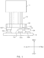
- FIGS. 3, 4, 5, and 6 are views illustrating an R-gear switch of FIG. 1 ;
- FIGS. 7, 8A, and 8B are views illustrating an operation of the shift-by-wire shifting control apparatus according to the embodiment of the present disclosure.
- FIG. 1 is a perspective view illustrating a shift-by-wire shifting control apparatus for a vehicle according to an embodiment of the present disclosure.
- the shift-by-wire shifting control apparatus 1 includes a housing 3 , a D-gear switch 5 , an N-gear switch 6 , and an R-gear switch 10 .
- shift-by-wire shifting control apparatus for electronically controlling gear shifting, instead of a mechanical gearshift, in a transmission system.
- the shift-by-wire shifting control apparatus may be implemented in various ways since the shift-by-wire shifting control apparatus is less limited in position or shape than the mechanical gearshift.
- the embodiment of the present disclosure relates to a shift-by-wire shifting control apparatus for providing a differentiated feeling of operation when a specific gear is selected, thereby preventing incorrect operation. More specifically, the shift-by-wire shifting control apparatus 1 according to the embodiment of the present disclosure has a basic feature wherein the R-gear switch 10 is movable between a first position and a second position, and the R-gear switch 10 is pushed by a first pressing force to move from the first position to a third position that is a specific position between the first and second positions and is pushed by a second pressing force greater than the first pressing force to move from the third position to the second position.
- the N-gear switch 6 or the D-gear switch 5 may be movable between a first position and a second position, and the N-gear switch 6 or the D-gear switch 5 may be pushed by a first pressing force to move from the first position to a third position that is a specific position between the first and second positions and may be pushed by a second pressing force greater than the first pressing force to move from the third position to the second position.
- the housing 3 may form the external appearance of the shift-by-wire shifting control apparatus 1 and may have an inner space for accommodating the remaining components of the shift-by-wire shifting control apparatus 1 .
- the housing 3 may be formed by combining upper and lower housings together.
- the shift-by-wire shifting control apparatus 1 may be configured to enable selection of a drive gear, a neutral gear, or a reverse gear.
- the shift-by-wire shifting control apparatus 1 may include the D-gear switch 5 corresponding to the drive gear, the N-gear switch 6 corresponding to the neutral gear, and the R-gear switch 10 corresponding to the reverse gear. Also, the shift-by-wire shifting control apparatus 1 may further include a P-gear switch 7 that is used for parking.
- the D-gear switch 5 , the N-gear switch 6 , the R-gear switch 10 , and the P-gear switch 7 may be installed in the housing 3 such that part of each switch is exposed outside the housing 3 for a push operation.
- the D-gear switch 5 , the N-gear switch 6 , the R-gear switch 10 , and the P-gear switch 7 may each include a button exposed above the housing 3 for a push operation.
- the D-gear switch 5 , the N-gear switch 6 , the R-gear switch 10 , and the P-gear switch 7 may each include a button cap that is curved downward. In the case where the button cap is curved upward, a user is more likely to incorrectly push an unintended switch in attempting to operate the shift-by-wire shifting control apparatus 1 .
- the D-gear switch 5 , the N-gear switch 6 , the R-gear switch 10 , and the P-gear switch 7 may each include the button cap, the top side of which is concave downward, thereby reducing incorrect operation.
- the R-gear switch 10 , the N-gear switch 6 , and the D-gear switch 5 may be arranged in sequence from front to rear. This is intended to reduce a risk of incorrect operation and provide ease of operation to the user by arranging the switches as in a traditional shifting control apparatus.
- the P-gear switch 7 may be disposed on a side, for example, the left side, of the R-, N-, and D-gear switches 10 , 6 , and 5 arranged in sequence from front or rear.
- the P-gear switch 7 may include a button larger than those of the D-gear switch 5 , the N-gear switch 6 , and the R-gear switch 10 and may provide a different feeling of operation than the D-gear switch 5 , the N-gear switch 6 , and the R-gear switch 10 .
- the housing 3 may have a shape including switch insertion openings into which the D-gear switch 5 , the N-gear switch 6 , the R-gear switch 10 , and the P-gear switch 7 are inserted.
- FIG. 2 is a view illustrating the N-gear switch of FIG. 1 .
- the N-gear switch 6 may include an N-gear button cap 61 , an N-gear button guide 62 , N-gear rubber domes 63 , and an N-gear substrate 64 .
- the N-gear button cap 61 may be installed in the housing 3 such that the N-gear button cap 61 is exposed above the housing 3 for a push operation.
- the N-gear button guide 62 may be vertically combined with the N-gear button cap 61 and may be installed in the housing 3 so as to be slidable by pushing the N-gear button cap 61 .
- the housing 3 may include a guide hole or a guide groove for guiding the sliding of the N-gear button guide 62 .
- the N-gear button guide 62 may include a guide protrusion or a guide protruding line that is inserted into the guide hole or the guide groove formed in the housing 3 .
- the N-gear button guide 62 may slide in the vertical direction.
- An oblique push operation inclined at a predetermined angle with respect to the vertical direction, as well as a vertical push operation, may be applied to the N-gear button cap 61 .
- the N-gear button guide 62 may be vertically moved.
- the combination of the N-gear button cap 61 and the N-gear button guide 62 may be referred to as an N-gear button assembly 61 and 62 .
- the N-gear switch 6 may include the N-gear rubber domes 63 that are compressively deformed by pushing the N-gear button assembly 61 and 62 .
- the N-gear rubber domes 63 are parts deformed when being pressed. Therefore, the N-gear rubber domes 63 may be referred to as what are called push deformation parts.
- Each of the N-gear rubber domes 63 may include contact portions (not illustrated) that conducts electricity when the N-gear rubber domes 63 are compressively deformed.
- the N-gear rubber domes 63 When the N-gear button assembly 61 and 62 is pushed, the N-gear rubber domes 63 may be compressively deformed and the contact portions may conduct electricity to generate an electrical signal.
- three N-gear rubber domes 63 may be provided to ensure signal stability.
- one rubber dome may be disposed in front, and the remaining two rubber domes may be disposed behind the rubber dome ahead.
- the two rubber domes behind may have bilateral symmetry with respect to a virtual line passing through the rubber dome ahead and extending in the fore/aft direction.
- the shift-by-wire shifting control apparatus 1 may be configured such that a signal for gear shifting to N is generated when at least two of the contact portions in the N-gear rubber domes 63 arranged as described above conduct electricity.
- the N-gear rubber domes 63 may be disposed on the N-gear substrate 64 .
- the N-gear substrate 64 may be integrated with the N-gear rubber domes 63 .
- the N-gear substrate 64 may include a membrane integrated with the N-gear rubber domes 63 .
- the D-gear switch 5 and the P-gear switch 7 may have the same configuration as, or a configuration similar to, that of the N-gear switch 6 . That is, the D-gear switch 5 and the P-gear switch 7 may include a button assembly that is moved by a push operation and rubber domes that are compressively deformed by pushing the button assembly, and may be configured such that, when the rubber domes are compressively deformed, contact portions in the rubber domes conduct electricity to generate a signal for gear shifting.
- FIGS. 3 to 6 are views illustrating the R-gear switch of FIG. 1 .
- the R-gear switch 10 may be pressed stepwise.
- the R-gear switch 10 may be movable between a first position and a second position.
- the R-gear switch 10 may be pushed by a first pressing force to move from the first position to a third position between the first and second positions and may be pushed by a second pressing force greater than the first pressing force to move from the third position to the second position.
- the R-gear switch 10 may provide a feeling of operation in two steps.
- the R-gear switch 10 may provide a different feeling of operation to a user than the other switches including the N-gear switch 6 , thereby preventing the R-gear switch 10 from being incorrectly operated.
- the R-gear switch 10 may include an R-gear button cap 11 , an R-gear button guide 12 , an R-gear rubber dome 13 , and a bridge 15 .
- the R-gear button cap 11 may be installed in the housing 3 such that the R-gear button cap 11 is exposed above the housing 3 for a push operation.
- the R-gear button guide 12 may be vertically combined with the R-gear button cap 11 .
- the R-gear button guide 12 may be installed in the housing 3 so as to be slidable by pushing the R-gear button cap 11 .
- the R-gear button guide 12 may include a button guide body 121 and a button guide protruding end 122 .
- the button guide body 121 may have a polygonal prism shape that extends in the vertical direction.
- the button guide body 121 may have a groove or a hole formed in the middle thereof.
- the button guide body 121 may have a hollow rectangular prism shape.
- the button guide body 121 may include one or more coupling protrusions 1211 for coupling the button guide body 121 to the R-gear button cap 11 .
- the button guide body 121 may be combined with the R-gear button cap 11 , with a portion of the button guide body 121 inserted into the R-gear button cap 11 .
- the coupling protrusions 1211 may be engaged with coupling parts on the R-gear button cap 11 to support the coupling of the R-gear button cap 11 and the button guide body 121 .
- the button guide body 121 may further include one or more guide protrusions 1212 .
- the guide protrusions 1212 may extend on lateral sides of the button guide body 121 in the direction in which the button guide body 121 slides.
- the housing 3 may include guide holes or guide grooves to be engaged with the guide protrusions 1212 for guiding the sliding of the R-gear button guide 12 .
- the guide holes or the guide grooves for guiding the sliding of the R-gear button guide 12 may be formed in the switch insertion opening of the housing 3 into which the R-gear button guide 12 is inserted.
- the guide protrusions 1212 may be inserted at least partly into the guide holes or the guide grooves formed in the housing 3 to guide the movement of the R-gear button guide 12 .
- the button guide protruding end 122 may protrude from the button guide body 121 in directions perpendicular to the moving direction of the R-gear button guide 12 .
- the button guide protruding end 122 may protrude from a lower end of the button guide body 121 in the fore/aft directions or in the left/right directions.
- the button guide protruding end 122 may function to prevent the combination of the R-gear button cap 11 and the R-gear button guide 12 from being separated from the housing 3 .
- the housing 3 has the switch insertion opening into which the R-gear button cap 11 and the R-gear button guide body 121 are inserted.
- the switch insertion opening may include an outside end that is open toward the outside of the housing 3 and an inside end that is open toward the inside of the housing 3 .
- the button guide protruding end 122 may be brought into contact with the inside end of the switch insertion opening and may prevent the R-gear button cap 11 and the R-gear button guide 12 from being separated from the housing 3 .
- R-gear button cap 11 The combination of the R-gear button cap 11 and the R-gear button guide 12 may be referred to as an R-gear button assembly 11 and 12 .
- the R-gear rubber dome 13 may include first rubber domes 131 a and 131 b , second rubber domes 132 a and 132 b , and a third rubber dome 133 that are compressively deformed by pushing the R-gear button assembly 11 and 12 .
- the rubber domes are compressively deformed when a pressing force is applied thereto and are restored to their original shapes by elasticity when the pressing force is removed. Therefore, the rubber domes may be referred to as what are called push deformation parts. That is, the first, second, and third rubber domes may be referred to as the first, second, and third push deformation parts.
- the second rubber domes 132 a and 132 b may include contact portions (not illustrated), respectively, which conduct electricity when the second rubber domes 132 a and 132 b are compressively deformed.
- Various types of conventional rubber domes configured to allow contact portions to conduct electricity when the rubber domes are compressively deformed may be used as the second rubber domes 132 a and 132 b .
- the second rubber domes 132 a and 132 b may be configured such that the contact portions conduct electricity when the second rubber domes 132 a and 132 b are compressively deformed by a predetermined height or more. That is, the second rubber domes 132 a and 132 b may be configured such that the contact portions do not conduct electricity until the second rubber domes 132 a and 132 b are compressively deformed to a predetermined depth or more.
- the third rubber dome 133 may include a contact portion (not illustrated) that conducts electricity when the third rubber dome 133 is compressively deformed.
- the third rubber dome 133 may be configured such that the contact portion conducts electricity when the third rubber dome 133 is compressively deformed by a predetermined height or more.
- the first rubber domes 131 a and 131 b , the second rubber domes 132 a and 132 b , and the third rubber dome 133 may elastically support the R-gear button assembly 11 and 12 to allow the R-gear button assembly 11 and 12 to return to the original position before a push operation is applied. Accordingly, when an external force applied to the R-gear button cap 11 is removed, the R-gear button cap 11 and the R-gear button guide 12 may be restored to the original position by the elastic force of the R-gear rubber dome 13 .
- the third rubber dome 133 , the first rubber domes 131 a and 131 b , and the second rubber domes 132 a and 132 b may be arranged in sequence from front to rear.
- the third rubber dome 133 , the second rubber domes 132 a and 132 b , and the first rubber domes 131 a and 131 b may be arranged in sequence from front to rear.
- those skilled in the art may appropriately modify and apply the structure to be described below.
- the pair of first rubber domes 131 a and 131 b may have bilateral symmetry with respect to a virtual line passing through the third rubber dome 133 and extending in the fore/aft direction, and the pair of second rubber domes 132 a and 132 b may have bilateral symmetry with respect to the virtual line.
- the R-gear button guide 12 may be elastically supported upward in a horizontal position by the first rubber domes 131 a and 131 b that have bilateral symmetry, the second rubber domes 132 a and 132 b that have bilateral symmetry, and the third rubber dome 133 .
- the first rubber domes 131 a and 131 b , the second rubber domes 132 a and 132 b , and the third rubber dome 133 may be disposed on an R-gear substrate 14 .
- the R-gear substrate 14 may be integrated with the first rubber domes 131 a and 131 b , the second rubber domes 132 a and 132 b , and the third rubber dome 133 .
- the R-gear substrate 14 may include a membrane integrated with the R-gear rubber dome 13 .
- the R-gear substrate 14 may be connected or integrated with the N-gear substrate 64 .
- the bridge 15 may transmit a force applied to the R-gear button assembly 11 and 12 to the first rubber domes 131 a and 131 b and the second rubber domes 132 a and 132 b.
- the bridge 15 may include a bridge body 151 and a bridge protrusion 152 .
- the bridge body 151 may have one end brought into contact with the first rubber domes 131 a and 131 b .
- the bridge body 151 may have an opposite end brought into contact with the second rubber domes 132 a and 132 b.
- the bridge body 151 may include, at the one end, a first rubber dome receiving part 153 into which a portion of each of the first rubber dome 131 a and 131 b is inserted.
- the bridge body 151 may include, at the opposite end, a second rubber dome receiving part 154 into which a portion of each of the second rubber domes 132 a and 132 b is inserted.
- the first rubber dome receiving part 153 may correspond to the shape of the first rubber domes 131 a and 131 b .
- the first rubber dome receiving part 153 may have an inner space with a larger diameter than those of the first rubber domes 131 a and 131 b.
- the second rubber dome receiving part 154 may correspond to the shape of the second rubber domes 132 a and 132 b .
- the second rubber dome receiving part 154 may have an inner space with a larger diameter than those of the second rubber domes 132 a and 132 b.
- the bridge 15 may remain coupled with the first rubber domes 131 a and 131 b and the second rubber domes 132 a and 132 b , and when the R-gear switch 10 is operated, the bridge 15 may be prevented from being separated from its position and the R-gear switch 10 may be stably operated.
- the bridge protrusion 152 may protrude from the bridge body 151 toward the R-gear button guide 12 .
- the bridge protrusion 152 may extend in the left/right direction such that the bridge protrusion 152 and the R-gear button guide 12 have a contact line extending in the left/right direction, strictly speaking, a contact surface extending in the left/right direction.
- the bridge protrusion 152 When the R-gear switch 10 is pressed, the bridge protrusion 152 is pressed and inclined forward and downward. In the case where the bridge protrusion 152 extends in any direction between the fore/aft direction and the left/right direction rather than in the left/right direction, the bridge protrusion 152 may not be uniformly pressed by the R-gear button guide 12 , and therefore the bridge 15 may be inclined to the left or right. That is, the bridge 15 may pitch and roll.
- the second rubber domes 132 a and 132 b pressed by the bridge 15 also may not uniformly receive force and may be distorted to the left or right, and signal generation by conduction of electricity by the contact portions may be unstable.
- the bridge protrusion 152 may extend in the left/right direction to allow a force transmitted from the R-gear button guide 12 to be uniformly applied to the bridge 15 .
- the bridge protrusion 152 does not necessarily have to extend only in the left/right direction and may extend in a direction with the left/right direction as a main component.
- the bridge protrusion 152 may be disposed closer to the one end of the bridge body 151 that is brought into contact with the first rubber dome 131 a or 131 b than the opposite end of the bridge body 151 that is brought into contact with the second rubber dome 132 a or 132 b.
- the first rubber domes 131 a and 131 b may receive a larger pressing force than the second rubber domes 132 a and 132 b and may be more easily compressively deformed than the second rubber domes 132 a and 132 b.
- the first rubber domes 131 a and 131 b may be formed to be more easily compressively deformed than the second rubber domes 132 a and 132 b .
- the first rubber domes 131 a and 131 b may have a lower modulus of elasticity than the second rubber domes 132 a and 132 b . Therefore, when the same force is applied to the first rubber domes 131 a and 131 b and the second rubber domes 132 a and 132 b , the first rubber domes 131 a and 131 b may be deformed prior to the second rubber domes 132 a and 132 b.
- the first rubber domes 131 a and 131 b may be easily deformed more than the second rubber domes 132 and 132 b.
- the bridge 15 may include a pair of bridges 15 arranged in the left/right direction.
- the pair of bridges 15 may be connected to the pair of first rubber domes 131 a and 131 b arranged in the left/right direction and the pair of second rubber domes 132 a and 132 b arranged in the left/right direction.
- elastic forces of the first rubber domes 131 a and 131 b and the second rubber domes 132 a and 132 b may be transmitted to the R-gear button assembly 11 and 12 in bilateral symmetry, and the R-gear button assembly 11 and 12 may be elastically supported upward without leaning to the left or right.
- the button guide protruding end 122 may include a third rubber dome receiving part 1221 .
- the third rubber dome receiving part 1221 may extend downward from the bottom of the button guide protruding end 122 .
- the third rubber dome 133 may be coupled to the R-gear button guide 12 , with a portion of the third rubber dome 133 inserted into the third rubber dome receiving part 1221 .
- the above-configured R-gear switch 10 has a feature wherein when a first pressing force is applied to the R-gear button assembly 11 and 12 , the first rubber domes 131 a and 131 b are compressively deformed, but the second rubber domes 132 a and 132 b are not compressively deformed to the extent to which the contact portions conduct electricity, and when a second pressing force greater than the first pressing force is applied to the R-gear button assembly 11 and 12 , the second rubber domes 132 a and 132 b are compressively deformed to the extent to which the contact portions conduct electricity.
- the R-gear switch 10 when the R-gear switch 10 is pushed by a pressure less than a predetermined pressure, the R-gear switch 10 is inserted to a predetermined depth, but no electrical signal is generated, and when the R-gear switch 10 is pushed by a pressure the same as the predetermined pressure or more, the R-gear switch 10 is further inserted and an electrical signal is generated.
- the R-gear switch 10 may be configured such that an electrical signal for gear shifting to R is generated when the contact portion in the third rubber dome 133 conducts electricity and at least one of the contact portions in the pair of second rubber domes 132 a and 132 b conducts electricity. Accordingly, the stability of the electrical signal may be ensured.
- the above-configured R-gear switch 10 may provide a different feeling of operation to a user than the other switches (the N-gear switch 6 and the D-gear switch 5 ), thereby enabling the user to distinguish the R-gear switch 10 from the other switches with only the feeling of operation.
- the shift-by-wire shifting control apparatus 1 may be prevented from being incorrectly operated, and even though the user incorrectly operates the shift-by-wire shifting control apparatus 1 , the user may easily recognize the incorrect operation.
- FIGS. 7, 8A, and 8B are views illustrating an operation of the shift-by-wire shifting control apparatus according to the embodiment of the present disclosure.
- FIG. 7 is a schematic diagram of the R-gear switch 10 , where FIG. 7 schematically illustrates the coupling relation between a lower end portion of the R-gear button guide 12 , the bridge 15 , the first rubber domes 131 a and 131 b , and the second rubber domes 132 a and 132 b.
- the leftmost diagram in FIG. 7 illustrates a state in which the R-gear switch 10 is located at the original position before a push operation is applied thereto.
- the bridge protrusion 152 is located closer to the first rubber domes 131 a and 131 b than the second rubber domes 132 a and 132 b , the first rubber domes 131 a and 131 b are more easily deformed than the second rubber domes 132 a and 132 b according to the principle of a lever.
- Equations 1 and 2 are momentum equilibrium equations for the bridge 15 .
- the pressing force that has to be applied to the R-gear switch 10 to compressively deform the first rubber domes 131 a and 131 b the pressing force that has to be applied to the R-gear switch 10 to compressively deform the second rubber domes 132 a and 132 b
- the elastic force of the first rubber domes 131 a and 131 b the elastic force of the second rubber domes 132 a and 132 b
- F BUTTON_1st F BUTTON_2nd
- F KEY-1st F KEY-2nd
- Equation 1 is a momentum equilibrium equation in the state in which the pressing force applied to the bridge 15 and the elastic force F KEY-1st of the first rubber domes 131 a and 131 b are in equilibrium right before the first rubber domes 131 a and 13 b are compressively deformed.
- Equation 2 is a momentum equilibrium equation in the state in which the pressing force applied to the bridge 15 and the elastic force F KEY_2nd of the second rubber domes 132 a and 132 b are in equilibrium right before the second rubber domes 132 a and 132 b are compressively deformed.
- Equation 5 may be obtained by arranging Equations 3 and 4.
- the first rubber domes 131 a and 131 b are compressively deformed more than the second rubber domes 132 a and 132 b and the R-gear switch 10 is pushed to a depth of D 1
- the second pressing force F BUTTON_2nd greater than the first pressing force F BUTTON_1st is applied to the R-gear switch 10
- the second rubber domes 132 a and 132 b are compressively deformed and the R-gear switch 10 is pushed to a depth of D 2 .
- the protruding length of the button guide protruding end 122 and the protruding length of the bridge protrusion 152 may be determined such that the button guide protruding end 122 is not brought into contact with the bridge body 151 when the R-gear switch 10 is pushed to the depth D 1 .
- the one end of the R-gear button guide 12 may be prevented from being brought into contact with the one end of the bridge 15 by decreasing the length of the button guide protruding end 122 in the left/right direction.
- the one end of the R-gear button guide 12 may be prevented from being brought into contact with the one end of the bridge 15 by increasing the height by which the bridge protrusion 152 protrudes.
- a difference in operation between the R-gear switch 10 and the remaining switches may be determined.
- the R-gear switch 10 may provide a feeling of operation in stages.
- an operating force of Fp1 is required to push the R-gear switch 10 to a depth of Sp1 or more. Due to the nature of the rubber domes, the rubber domes may be compressively deformed in succession by an operating force less than Fp1 after being compressively deformed to a predetermined level or higher.
- a user when operating the R-gear switch 10 , may notice that the repulsive force of the switch increases in the depth range of 0 to Sp1 and then decreases in the depth range of Sp1 to Sb1. Consequently, the user may firstly notice a feeling of operation.
- an operating force of Fp2 is required to push the R-gear switch 10 to a depth of Sp2 or more.
- the user when operating the R-gear switch 10 , may notice that the repulsive force of the switch increases in the depth range of Sb1 to Sp2 and then decreases in the depth range of Sp2 to Sb2. Consequently, the user may secondly notice a feeling of operation.
- the N-gear switch 6 , the D-gear switch 5 , and the P-gear switch 7 may provide a simpler feeling of operation than the R-gear switch 10 since the repulsive forces of the switches increase and then decrease only once.
- the shift-by-wire shifting control apparatus 1 may prevent the R-gear switch 10 from being incorrectly operated, thereby improving vehicle driving stability.
- the R-gear switch provides a different feeling of operation than the N-gear switch and the D-gear switch, thereby preventing the shift-by-wire shifting control apparatus from being incorrectly operated.
- the R-gear switch includes the first push deformation part compressively deformed when the R-gear switch is pushed by the first pressing force and the second push deformation part compressively deformed when the R-gear switch is pushed by the second pressing force greater than the first pressing force, and the second push deformation part includes the contact portion, whereby a different feeling of operation may be implemented with the simple configuration.
- the shift-by-wire shifting control apparatus may be prevented from being incorrectly operated, thereby ensuring driving stability of a vehicle that uses the shift-by-wire shifting control apparatus.
Landscapes
- Engineering & Computer Science (AREA)
- General Engineering & Computer Science (AREA)
- Mechanical Engineering (AREA)
- Arrangement Or Mounting Of Control Devices For Change-Speed Gearing (AREA)
Abstract
Description
ΣM 1=−(F KEY_1st)·(a+b)+(F BUTTON_1st)·(b)=0
ΣM 2=−(F BUTTON_2nd)·(a)+(F KEY_2nd)·(a+b)=0 Equation 2
(F BUTTON_1st)=(F KEY_1st)·(a+b)/
(F BUTTON_2nd)=(F KEY_2nd)·(a+b)/a Equation 4
Claims (15)
Applications Claiming Priority (2)
| Application Number | Priority Date | Filing Date | Title |
|---|---|---|---|
| KR10-2018-0140286 | 2018-11-14 | ||
| KR1020180140286A KR102598959B1 (en) | 2018-11-14 | 2018-11-14 | Shift by wire type shifting control apparatus for a vehicle |
Publications (2)
| Publication Number | Publication Date |
|---|---|
| US20200149628A1 US20200149628A1 (en) | 2020-05-14 |
| US10760679B2 true US10760679B2 (en) | 2020-09-01 |
Family
ID=70551075
Family Applications (1)
| Application Number | Title | Priority Date | Filing Date |
|---|---|---|---|
| US16/206,996 Expired - Fee Related US10760679B2 (en) | 2018-11-14 | 2018-11-30 | Shift-by-wire shifting control apparatus for vehicle |
Country Status (2)
| Country | Link |
|---|---|
| US (1) | US10760679B2 (en) |
| KR (1) | KR102598959B1 (en) |
Cited By (2)
| Publication number | Priority date | Publication date | Assignee | Title |
|---|---|---|---|---|
| USD919519S1 (en) * | 2019-08-14 | 2021-05-18 | Hyundai Motor Company | Shift-by-wire controller for an automobile |
| US20230366459A1 (en) * | 2022-05-16 | 2023-11-16 | Kabushiki Kaisha Tokai-Rika-Denki-Seisakusho | Shift device |
Citations (17)
| Publication number | Priority date | Publication date | Assignee | Title |
|---|---|---|---|---|
| US5152392A (en) * | 1990-06-11 | 1992-10-06 | Fujitsu Limited | Push switch with improved actuator assembly |
| US6295887B1 (en) * | 1999-01-11 | 2001-10-02 | Grand Haven Stamped Products, Division Of Jsj Corporation | Miniaturized transmission shifter |
| JP2002254950A (en) | 2001-03-01 | 2002-09-11 | Tokai Rika Co Ltd | Switching device of shift device |
| JP2012071649A (en) | 2010-09-28 | 2012-04-12 | Tokai Rika Co Ltd | Shift device |
| JP2013159270A (en) | 2012-02-07 | 2013-08-19 | Honda Motor Co Ltd | Vehicular shift device |
| US20150107971A1 (en) * | 2013-10-22 | 2015-04-23 | Alps Electric Co., Ltd. | Switching device |
| US20150176699A1 (en) * | 2012-06-08 | 2015-06-25 | Honda Motor Co., Ltd. | Shift device for vehicle |
| US20150363006A1 (en) * | 2014-06-16 | 2015-12-17 | Microsoft Corporation | Spring Configuration For Touch-Sensitive Input Device |
| KR20170000007A (en) | 2015-06-22 | 2017-01-02 | 현대자동차주식회사 | 2-Step Button Type Electronic Auto Shift Lever |
| US20170227118A1 (en) * | 2016-02-10 | 2017-08-10 | Ford Global Technologies, Llc | Pushbutton vehicle shifter interface using proximity sensing |
| US20170227119A1 (en) * | 2016-02-10 | 2017-08-10 | Ford Global Technologies, Llc | Vehicle shifter interface using proximity sensing |
| US20170274765A1 (en) * | 2016-03-23 | 2017-09-28 | Ford Global Technologies, Llc | Pushbutton vehicle shifter interface |
| US9970531B2 (en) | 2012-12-07 | 2018-05-15 | Kabushiki Kaisha Tokai-Rika-Denki-Seisakusho | Shift device |
| US20190145513A1 (en) * | 2016-06-13 | 2019-05-16 | Kabushiki Kaisha Tokai Rika Denki Seisakusho | Shift device |
| US20190257412A1 (en) * | 2018-02-20 | 2019-08-22 | Ghsp, Inc. | Wire-based transmission shifter with integrated electrical switch control |
| US20190323599A1 (en) * | 2018-04-23 | 2019-10-24 | Ficosa International (Taicang) Co. Ltd. | Vehicle gear shift module |
| US10605354B2 (en) * | 2017-06-26 | 2020-03-31 | Kyung Chang Industrial Co., Ltd. | Button-type transmission control device |
Family Cites Families (1)
| Publication number | Priority date | Publication date | Assignee | Title |
|---|---|---|---|---|
| JPH0346926U (en) * | 1989-09-13 | 1991-04-30 |
-
2018
- 2018-11-14 KR KR1020180140286A patent/KR102598959B1/en active Active
- 2018-11-30 US US16/206,996 patent/US10760679B2/en not_active Expired - Fee Related
Patent Citations (18)
| Publication number | Priority date | Publication date | Assignee | Title |
|---|---|---|---|---|
| US5152392A (en) * | 1990-06-11 | 1992-10-06 | Fujitsu Limited | Push switch with improved actuator assembly |
| US6295887B1 (en) * | 1999-01-11 | 2001-10-02 | Grand Haven Stamped Products, Division Of Jsj Corporation | Miniaturized transmission shifter |
| JP2002254950A (en) | 2001-03-01 | 2002-09-11 | Tokai Rika Co Ltd | Switching device of shift device |
| JP2012071649A (en) | 2010-09-28 | 2012-04-12 | Tokai Rika Co Ltd | Shift device |
| JP2013159270A (en) | 2012-02-07 | 2013-08-19 | Honda Motor Co Ltd | Vehicular shift device |
| JP5963857B2 (en) | 2012-06-08 | 2016-08-03 | 本田技研工業株式会社 | Vehicle shift device |
| US20150176699A1 (en) * | 2012-06-08 | 2015-06-25 | Honda Motor Co., Ltd. | Shift device for vehicle |
| US9970531B2 (en) | 2012-12-07 | 2018-05-15 | Kabushiki Kaisha Tokai-Rika-Denki-Seisakusho | Shift device |
| US20150107971A1 (en) * | 2013-10-22 | 2015-04-23 | Alps Electric Co., Ltd. | Switching device |
| US20150363006A1 (en) * | 2014-06-16 | 2015-12-17 | Microsoft Corporation | Spring Configuration For Touch-Sensitive Input Device |
| KR20170000007A (en) | 2015-06-22 | 2017-01-02 | 현대자동차주식회사 | 2-Step Button Type Electronic Auto Shift Lever |
| US20170227118A1 (en) * | 2016-02-10 | 2017-08-10 | Ford Global Technologies, Llc | Pushbutton vehicle shifter interface using proximity sensing |
| US20170227119A1 (en) * | 2016-02-10 | 2017-08-10 | Ford Global Technologies, Llc | Vehicle shifter interface using proximity sensing |
| US20170274765A1 (en) * | 2016-03-23 | 2017-09-28 | Ford Global Technologies, Llc | Pushbutton vehicle shifter interface |
| US20190145513A1 (en) * | 2016-06-13 | 2019-05-16 | Kabushiki Kaisha Tokai Rika Denki Seisakusho | Shift device |
| US10605354B2 (en) * | 2017-06-26 | 2020-03-31 | Kyung Chang Industrial Co., Ltd. | Button-type transmission control device |
| US20190257412A1 (en) * | 2018-02-20 | 2019-08-22 | Ghsp, Inc. | Wire-based transmission shifter with integrated electrical switch control |
| US20190323599A1 (en) * | 2018-04-23 | 2019-10-24 | Ficosa International (Taicang) Co. Ltd. | Vehicle gear shift module |
Cited By (3)
| Publication number | Priority date | Publication date | Assignee | Title |
|---|---|---|---|---|
| USD919519S1 (en) * | 2019-08-14 | 2021-05-18 | Hyundai Motor Company | Shift-by-wire controller for an automobile |
| US20230366459A1 (en) * | 2022-05-16 | 2023-11-16 | Kabushiki Kaisha Tokai-Rika-Denki-Seisakusho | Shift device |
| US11953088B2 (en) * | 2022-05-16 | 2024-04-09 | Kabushiki Kaisha Tokai-Rika-Denki-Seisakusho | Shift device |
Also Published As
| Publication number | Publication date |
|---|---|
| US20200149628A1 (en) | 2020-05-14 |
| KR102598959B1 (en) | 2023-11-06 |
| KR20200056226A (en) | 2020-05-22 |
Similar Documents
| Publication | Publication Date | Title |
|---|---|---|
| US9683655B2 (en) | Shift device for vehicle | |
| EP2988375B1 (en) | Connector device | |
| US10760679B2 (en) | Shift-by-wire shifting control apparatus for vehicle | |
| US5721405A (en) | Tactile feedback mechanism for a multidirectional switch | |
| JP2009266508A (en) | Electric connector for flat conductor | |
| KR20040043896A (en) | Push button | |
| US20020066650A1 (en) | Multi-stage click switch | |
| US7960664B2 (en) | Seesaw switch | |
| KR101051090B1 (en) | Kickdown switch on accelerator pedal | |
| KR20160145916A (en) | Button type electronic shift lever system | |
| US20110031097A1 (en) | Electrical switch assembly with angled plunger | |
| JP2022090961A (en) | Connector assembly | |
| JP4464846B2 (en) | Switch device | |
| EP3358590A1 (en) | Rocker switch device | |
| US5448026A (en) | Double-axis key switch | |
| KR102814425B1 (en) | Sunroof switch unit for vehicle | |
| JP2012064329A (en) | Connector structure | |
| KR100461823B1 (en) | A shift lever assembly of manual transmission | |
| KR200459979Y1 (en) | Paddle shifting lever switching unit | |
| CN223975535U (en) | Toggle shifter and vehicle | |
| KR100877959B1 (en) | Dual Detent Pin | |
| US20220375703A1 (en) | Switch device | |
| KR101662542B1 (en) | Bidirectional Split Type Electronic Auto Shift Lever | |
| JP5659891B2 (en) | Electronic equipment | |
| KR100583877B1 (en) | Mirror switch device |
Legal Events
| Date | Code | Title | Description |
|---|---|---|---|
| FEPP | Fee payment procedure |
Free format text: ENTITY STATUS SET TO UNDISCOUNTED (ORIGINAL EVENT CODE: BIG.); ENTITY STATUS OF PATENT OWNER: LARGE ENTITY |
|
| STPP | Information on status: patent application and granting procedure in general |
Free format text: NOTICE OF ALLOWANCE MAILED -- APPLICATION RECEIVED IN OFFICE OF PUBLICATIONS |
|
| ZAAA | Notice of allowance and fees due |
Free format text: ORIGINAL CODE: NOA |
|
| ZAAB | Notice of allowance mailed |
Free format text: ORIGINAL CODE: MN/=. |
|
| STPP | Information on status: patent application and granting procedure in general |
Free format text: PUBLICATIONS -- ISSUE FEE PAYMENT RECEIVED |
|
| STCF | Information on status: patent grant |
Free format text: PATENTED CASE |
|
| FEPP | Fee payment procedure |
Free format text: MAINTENANCE FEE REMINDER MAILED (ORIGINAL EVENT CODE: REM.); ENTITY STATUS OF PATENT OWNER: LARGE ENTITY |
|
| LAPS | Lapse for failure to pay maintenance fees |
Free format text: PATENT EXPIRED FOR FAILURE TO PAY MAINTENANCE FEES (ORIGINAL EVENT CODE: EXP.); ENTITY STATUS OF PATENT OWNER: LARGE ENTITY |
|
| STCH | Information on status: patent discontinuation |
Free format text: PATENT EXPIRED DUE TO NONPAYMENT OF MAINTENANCE FEES UNDER 37 CFR 1.362 |
|
| FP | Lapsed due to failure to pay maintenance fee |
Effective date: 20240901 |