US10759207B2 - Curved acrylic decorated article - Google Patents
Curved acrylic decorated article Download PDFInfo
- Publication number
- US10759207B2 US10759207B2 US16/137,806 US201816137806A US10759207B2 US 10759207 B2 US10759207 B2 US 10759207B2 US 201816137806 A US201816137806 A US 201816137806A US 10759207 B2 US10759207 B2 US 10759207B2
- Authority
- US
- United States
- Prior art keywords
- article
- substrate
- coating
- recited
- curved
- Prior art date
- Legal status (The legal status is an assumption and is not a legal conclusion. Google has not performed a legal analysis and makes no representation as to the accuracy of the status listed.)
- Active - Reinstated, expires
Links
Images


Classifications
-
- B—PERFORMING OPERATIONS; TRANSPORTING
- B41—PRINTING; LINING MACHINES; TYPEWRITERS; STAMPS
- B41M—PRINTING, DUPLICATING, MARKING, OR COPYING PROCESSES; COLOUR PRINTING
- B41M5/00—Duplicating or marking methods; Sheet materials for use therein
- B41M5/025—Duplicating or marking methods; Sheet materials for use therein by transferring ink from the master sheet
- B41M5/035—Duplicating or marking methods; Sheet materials for use therein by transferring ink from the master sheet by sublimation or volatilisation of pre-printed design, e.g. sublistatic
- B41M5/0355—Duplicating or marking methods; Sheet materials for use therein by transferring ink from the master sheet by sublimation or volatilisation of pre-printed design, e.g. sublistatic characterised by the macromolecular coating or impregnation used to obtain dye receptive properties
-
- B—PERFORMING OPERATIONS; TRANSPORTING
- B44—DECORATIVE ARTS
- B44C—PRODUCING DECORATIVE EFFECTS; MOSAICS; TARSIA WORK; PAPERHANGING
- B44C3/00—Processes, not specifically provided for elsewhere, for producing ornamental structures
- B44C3/08—Stamping or bending
- B44C3/087—Stamping or bending bending
-
- B—PERFORMING OPERATIONS; TRANSPORTING
- B29—WORKING OF PLASTICS; WORKING OF SUBSTANCES IN A PLASTIC STATE IN GENERAL
- B29C—SHAPING OR JOINING OF PLASTICS; SHAPING OF MATERIAL IN A PLASTIC STATE, NOT OTHERWISE PROVIDED FOR; AFTER-TREATMENT OF THE SHAPED PRODUCTS, e.g. REPAIRING
- B29C51/00—Shaping by thermoforming, i.e. shaping sheets or sheet like preforms after heating, e.g. shaping sheets in matched moulds or by deep-drawing; Apparatus therefor
-
- B—PERFORMING OPERATIONS; TRANSPORTING
- B41—PRINTING; LINING MACHINES; TYPEWRITERS; STAMPS
- B41M—PRINTING, DUPLICATING, MARKING, OR COPYING PROCESSES; COLOUR PRINTING
- B41M5/00—Duplicating or marking methods; Sheet materials for use therein
- B41M5/025—Duplicating or marking methods; Sheet materials for use therein by transferring ink from the master sheet
- B41M5/035—Duplicating or marking methods; Sheet materials for use therein by transferring ink from the master sheet by sublimation or volatilisation of pre-printed design, e.g. sublistatic
-
- B—PERFORMING OPERATIONS; TRANSPORTING
- B44—DECORATIVE ARTS
- B44F—SPECIAL DESIGNS OR PICTURES
- B44F1/00—Designs or pictures characterised by special or unusual light effects
- B44F1/02—Designs or pictures characterised by special or unusual light effects produced by reflected light, e.g. matt surfaces, lustrous surfaces
-
- D—TEXTILES; PAPER
- D06—TREATMENT OF TEXTILES OR THE LIKE; LAUNDERING; FLEXIBLE MATERIALS NOT OTHERWISE PROVIDED FOR
- D06P—DYEING OR PRINTING TEXTILES; DYEING LEATHER, FURS OR SOLID MACROMOLECULAR SUBSTANCES IN ANY FORM
- D06P3/00—Special processes of dyeing or printing textiles, or dyeing leather, furs, or solid macromolecular substances in any form, classified according to the material treated
- D06P3/02—Material containing basic nitrogen
- D06P3/04—Material containing basic nitrogen containing amide groups
- D06P3/24—Polyamides; Polyurethanes
- D06P3/26—Polyamides; Polyurethanes using dispersed dyestuffs
-
- D—TEXTILES; PAPER
- D06—TREATMENT OF TEXTILES OR THE LIKE; LAUNDERING; FLEXIBLE MATERIALS NOT OTHERWISE PROVIDED FOR
- D06P—DYEING OR PRINTING TEXTILES; DYEING LEATHER, FURS OR SOLID MACROMOLECULAR SUBSTANCES IN ANY FORM
- D06P5/00—Other features in dyeing or printing textiles, or dyeing leather, furs, or solid macromolecular substances in any form
- D06P5/003—Transfer printing
- D06P5/004—Transfer printing using subliming dyes
-
- B—PERFORMING OPERATIONS; TRANSPORTING
- B29—WORKING OF PLASTICS; WORKING OF SUBSTANCES IN A PLASTIC STATE IN GENERAL
- B29C—SHAPING OR JOINING OF PLASTICS; SHAPING OF MATERIAL IN A PLASTIC STATE, NOT OTHERWISE PROVIDED FOR; AFTER-TREATMENT OF THE SHAPED PRODUCTS, e.g. REPAIRING
- B29C51/00—Shaping by thermoforming, i.e. shaping sheets or sheet like preforms after heating, e.g. shaping sheets in matched moulds or by deep-drawing; Apparatus therefor
- B29C51/14—Shaping by thermoforming, i.e. shaping sheets or sheet like preforms after heating, e.g. shaping sheets in matched moulds or by deep-drawing; Apparatus therefor using multilayered preforms or sheets
-
- B—PERFORMING OPERATIONS; TRANSPORTING
- B29—WORKING OF PLASTICS; WORKING OF SUBSTANCES IN A PLASTIC STATE IN GENERAL
- B29K—INDEXING SCHEME ASSOCIATED WITH SUBCLASSES B29B, B29C OR B29D, RELATING TO MOULDING MATERIALS OR TO MATERIALS FOR MOULDS, REINFORCEMENTS, FILLERS OR PREFORMED PARTS, e.g. INSERTS
- B29K2033/00—Use of polymers of unsaturated acids or derivatives thereof as moulding material
- B29K2033/04—Polymers of esters
- B29K2033/08—Polymers of acrylic acid esters, e.g. PMA, i.e. polymethylacrylate
-
- B—PERFORMING OPERATIONS; TRANSPORTING
- B29—WORKING OF PLASTICS; WORKING OF SUBSTANCES IN A PLASTIC STATE IN GENERAL
- B29K—INDEXING SCHEME ASSOCIATED WITH SUBCLASSES B29B, B29C OR B29D, RELATING TO MOULDING MATERIALS OR TO MATERIALS FOR MOULDS, REINFORCEMENTS, FILLERS OR PREFORMED PARTS, e.g. INSERTS
- B29K2995/00—Properties of moulding materials, reinforcements, fillers, preformed parts or moulds
- B29K2995/0018—Properties of moulding materials, reinforcements, fillers, preformed parts or moulds having particular optical properties, e.g. fluorescent or phosphorescent
- B29K2995/0026—Transparent
-
- B—PERFORMING OPERATIONS; TRANSPORTING
- B41—PRINTING; LINING MACHINES; TYPEWRITERS; STAMPS
- B41M—PRINTING, DUPLICATING, MARKING, OR COPYING PROCESSES; COLOUR PRINTING
- B41M5/00—Duplicating or marking methods; Sheet materials for use therein
- B41M5/025—Duplicating or marking methods; Sheet materials for use therein by transferring ink from the master sheet
- B41M5/0256—Duplicating or marking methods; Sheet materials for use therein by transferring ink from the master sheet the transferable ink pattern being obtained by means of a computer driven printer, e.g. an ink jet or laser printer, or by electrographic means
-
- B—PERFORMING OPERATIONS; TRANSPORTING
- B41—PRINTING; LINING MACHINES; TYPEWRITERS; STAMPS
- B41M—PRINTING, DUPLICATING, MARKING, OR COPYING PROCESSES; COLOUR PRINTING
- B41M5/00—Duplicating or marking methods; Sheet materials for use therein
- B41M5/50—Recording sheets characterised by the coating used to improve ink, dye or pigment receptivity, e.g. for ink-jet or thermal dye transfer recording
- B41M5/52—Macromolecular coatings
- B41M5/5218—Macromolecular coatings characterised by inorganic additives, e.g. pigments, clays
-
- B—PERFORMING OPERATIONS; TRANSPORTING
- B41—PRINTING; LINING MACHINES; TYPEWRITERS; STAMPS
- B41M—PRINTING, DUPLICATING, MARKING, OR COPYING PROCESSES; COLOUR PRINTING
- B41M5/00—Duplicating or marking methods; Sheet materials for use therein
- B41M5/50—Recording sheets characterised by the coating used to improve ink, dye or pigment receptivity, e.g. for ink-jet or thermal dye transfer recording
- B41M5/52—Macromolecular coatings
- B41M5/5263—Macromolecular coatings characterised by the use of polymers obtained otherwise than by reactions only involving carbon-to-carbon unsaturated bonds
- B41M5/5281—Polyurethanes or polyureas
-
- Y—GENERAL TAGGING OF NEW TECHNOLOGICAL DEVELOPMENTS; GENERAL TAGGING OF CROSS-SECTIONAL TECHNOLOGIES SPANNING OVER SEVERAL SECTIONS OF THE IPC; TECHNICAL SUBJECTS COVERED BY FORMER USPC CROSS-REFERENCE ART COLLECTIONS [XRACs] AND DIGESTS
- Y10—TECHNICAL SUBJECTS COVERED BY FORMER USPC
- Y10T—TECHNICAL SUBJECTS COVERED BY FORMER US CLASSIFICATION
- Y10T428/00—Stock material or miscellaneous articles
- Y10T428/24—Structurally defined web or sheet [e.g., overall dimension, etc.]
- Y10T428/24802—Discontinuous or differential coating, impregnation or bond [e.g., artwork, printing, retouched photograph, etc.]
- Y10T428/24851—Intermediate layer is discontinuous or differential
- Y10T428/24868—Translucent outer layer
- Y10T428/24876—Intermediate layer contains particulate material [e.g., pigment, etc.]
Definitions
- the present invention relates generally to dye sublimation transfer printing onto synthetic organic polymers and polymeric articles.
- the invention relates to the production of a curved acrylic panel decorated by dye-sublimation.
- Certain fibrous materials such as polyester fabric and certain synthetic organic polymers such as acetyl, polycarbonate, and nylon can accept the diffusion of sublimable or disperse dyes directly and have no need to be coated before receiving the image.
- certain synthetic organic polymers such as acetyl, polycarbonate, and nylon can accept the diffusion of sublimable or disperse dyes directly and have no need to be coated before receiving the image.
- their natural ability to accept the diffusion of the dye does not ensure long term persistence of these dyes and often the image will blur or fade over time.
- acrylic blocks One article that uses a transferred image by a process of dye-sublimation is acrylic blocks.
- the thickness of these acrylic blocks is typically around 1′′ in order to position the block in a stable fashion without an additional base and for easy viewing of any decorations that might be applied to the block, such as photographs. Due to the ease at which larger panels can be knocked over, these blocks have been available in dimensions of up to 8′′ ⁇ 10′′. Panels with a thickness of greater than 1′′ are not generally decorated due to high cost.
- acrylic blocks are flat, polished edge forms a reflective plane within the block and causes an appealing optical effect.
- acrylic can be fabricated from “sheet-stock” on a just-in-time inventory basis where the larger coated sheet can be cut down as needed into various sizes immediately prior to shipping a decorated product.
- a disadvantage of acrylic articles is that a one inch thick acrylic is not only expensive but heavy, and the stability of a 1 inch base limits the potential height of an acrylic article. Thinner acrylic panels can be offered as a solution, however they require a stand to support them and the thinner they are more the susceptible to warping during manufacturing. Adding weights to maintain a flat shape during manufacturing can be used, but such weights can lead to surface damage of the acrylic.
- Curved glass is transparent and has a coating applied onto the outer side of the curve allowing an image to be viewed through the glass. Also, current techniques and formulations allow for images to be viewed from both sides. Hence, glass media have become popular for gifts and photo displays, and often are decorated for such uses.
- the advantage of utilizing glass is that the glass can be curved eliminating the need for a base, and glass does not require a significant thickness with thicknesses of 0.1875′′ typical. Moreover, glass can be formed into a curved shape and can therefore act as its own support on a flat surface, thereby not requiring an independent stand like a thin acrylic article might require. Other advantages include the ability for coated curved glass to be heated without warping.
- the invention comprises a process for applying a dye sublimation image to a curved plate of acrylic in a commercially reasonable time period.
- the process yields a curved acrylic photographic media comprising of an optically clear acrylic layer and an adjacent synthetic organic polymer containing both light scattering particulate and diffused disperse dyes.
- the layered article being formed into a curve or other shape immediately subsequent to receiving a graphic decoration by dye diffusion thermal transfer.
- FIG. 1 is a cross sectional diagram of a coated acrylic substrate
- FIG. 2 is a cross sectional diagram of the coated substrate shown in FIG. 1 positioned within a heat press in the process of receiving a dye sublimation image from a transfer media;
- FIG. 3 is a cross sectional diagram of the coated substrate shown in FIG. 2 after heat and pressure have caused the diffusion of the dye into the polymer coating;
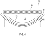
- FIG. 4 is a diagrammatic view of the now decorated substrate placed into a curved jig to cause the acrylic substrate to curve under the influence of gravity;
- FIG. 5 is perspective diagram of the article showing how light illuminates the image deposited on the surface of the article
- FIG. 6 is a process diagram showing the creation of a transfer media having a dye sublimation image formed thereon.
- FIG. 7 is a process diagram showing the manufacture of a curved acrylic article decorated with an image through dye sublimation.
- FIG. 1 shows a cross sectional view 10 of a 0.177′′ acrylic substrate 11 coated with a synthetic organic polymer 12 applied thereon.
- Acrylic substrate 11 is an optically clear thermoplastic such as cell cast or extruded acrylic, or polycarbonate.
- the substrate must be capable of being thermoformed and be of high optical clarity.
- the organic polymer 12 is a clear acrylic urethane coating modified by the addition of a light scattering pigment 13 that renders it a white translucent, partially opaque coating.
- the light scattering pigment 13 incudes nano-sized particles of titanium dioxide having an average particle size of 100 nm at a loading level of 20% by weight of solids.
- the coating 12 is applied by spraying onto the acrylic 11 resulting in a dry film buildup of 0.004′′. In the preferred embodiment, the coating dries at room temperate with a catalyzed reaction to induce polymerization.
- Coating 12 must be capable of bonding with the acrylic substrate 11 , but possess sufficient flexibility to allow the coated article to be formed into a curved shape while heated.
- Suitable coating bases are acrylic or urethane, or a hybrid mixture of both.
- the coating should either be extruded directly onto the product or applied by conventional coating deposition procedures such as spraying, curtain deposition, or a flow-over deposition.
- the coating may be cured either by low temperature thermal activation, or the application of a chemical catalyst, which is preferred.
- the coating 12 ideally is not cured by photo-initiated or electron-beam initiated reaction because polymers cured in this manner generally do not possess the ability to be heated and shape-formed after curing without cracking or delamination.
- Coating 12 also includes light scattering additives 13 .
- the coating must include particulate that is capable of scattering light, as opposed to reflecting the light.
- Suitable light scattering particulates include aluminum oxide, titanium dioxide, zirconium oxide, calcium carbonate, kaolin clay, ceramic nanoparticles, cerium oxide and other white appearance particulate.
- each particulate must be less than 400 nm in size so that each is smaller than any visible wavelength of light. This results in the particulate having a higher refractive index than the clear coating that supports the particles, resulting in suitable light scattering.
- the particulate should be white in color, and also renders the acrylic more scratch resistance.
- the particle additive is nano-particles of aluminum oxide.
- the loading level of the particulate should be sufficient to impart whiteness and a degree of opacity, but not of such concentrations that the coating ceases to be translucent or partially transparent. Therefore, nanoparticles in a range of 60 nm-200 nm at a loading level of between 10% and 30% by weight of solids of the coating are preferred.
- Coating thickness is also important.
- the coating 12 must be thick enough to allow the light attenuation caused by the particulate contained within it to render the article white and to allow the dyes, in concert with the particulate, to render a degree of opacity. This generally requires a coating thickness of at least 0.0015′′, but preferably greater than 0.0025′′ in thickness.
- the coating should not however be greater than 0.005′′ because as disperse dyes may fail to properly diffuse through the coating. The consequence of this is that the whiteness imparted by the particulate present between the acrylic interface and the threshold of the dye saturated part of the coating film causes a hazing of the image when viewed from non-coated side of the acrylic substrate. Therefore the optimal thickness of the coating is between 0.003′′ and 0.0045′′.
- FIG. 2 is may be seen the coated acrylic piece 10 from FIG. 1 now positioned in an arrangement 15 within a heat press 20 prepared to receive the transfer of a graphic image 16 from a printed transfer paper media 17 .
- the layering from the top of the stack of elements depicted in this cross sectional view includes a steel heat platen 19 heated to 365 degrees F., a porous PTFE coated Fiberglass sheet 18 to protect the platen 19 and provide for a breathable interface between the platen 19 and the transfer paper 17 .
- Below the breather liner 18 is transfer paper 17 having an image 16 printed thereon with disperse dyes that may be deposited via a suitable inkjet printer.
- the paper is oriented with print side facing downward against the coated side 12 of the coated substrate 11 as described in FIG. 1 .
- the substrate 11 is supported by a porous ceramic insulation layer 22 which prevents heat from dissipating from the acrylic below it.
- the ceramic insulation 22 furthermore allows for moisture of other gases to wick from the substrate 11 during the heating process.
- disperse dyes 16 held by transfer paper 17 have turned into gases by a sublimation phase change process and have diffused into the receptive polymer coating 12 thoroughly until reaching the surface of acrylic substrate 11 . This occurs after the assembly has been subject to 365 degrees F. for 2 minutes under a pressure of 20 PSI, and results in a decorated acrylic article 25 having a flat or planar shape when removed from the heat press 20 .
- article 25 has been removed from the heat press arrangement 15 following transfer of the image into the coating 12 and the now decorated article 25 has been placed on a curved metal jig 32 lined with a porous ceramic insulation 22 of the same nature as employed in the heat press arrangement 15 .
- the article 25 being of a temperature well exceeding its softening point and having been exposed to sufficient heat to raise the entirety of it to a uniform temperature, is placed on and has been conformed to the shape of the metal jig 32 under the influence of gravity.
- a flat weight 34 comprising a piece of aluminum has been placed upon the acrylic article 25 in such a manner as to only touch the article 25 at its edges and with minimal weight applied to prevent the article 25 from warping as it cools.
- weight 34 it is necessary to place a weight 34 on the cooling acrylic article 25 to prevent it from warping as it cools.
- the weight comprising a piece of metal such as aluminum sits on top of the acrylic and rests on each of the left and right edges of the acrylic as shown. If the weight 34 is too light it will not prevent the warping from taking place, but if it is too heavy it can damage the delicate edges of the heated article 25 .
- the jig 32 may be any metal material capable of being fabricated into a curve. Relatively thin aluminum sheet is ideal for the jig 32 , but any metal material capable of being formed in a curved fashion is satisfactory.
- the jig has a radius equal to the radius desired for the finished acrylic article 25 , and may be convex or concave in shape and include multiple curves as may be understood. However, the inventor has discovered that in the herein described process the acrylic article 25 generally should not include wave shapes that exceed 11 oscillations per 16 inches of lineal acrylic substrate to avoid damage.
- the jig is lined with a porous fabric or paper material 22 that acts as a liner to facilitate uniform cooling of the article 25 as heat is drawn out of the acrylic and into the ambient air above it. The material 22 also allows heated air to be pulled out of the acrylic via a gap 23 between the article surface and the weight as shown.
- FIG. 5 shows the article 33 now cooled into its curved shape and positioned on a flat surface in an upright position, as potentially on a table top surface.
- a light source 28 such as from ambient light in a lighted room shines onto the front and back of the article surface with the light being scattered 38 within the dyed polymer 37 , thereby illuminating the image formed by the transferred dye.
- the edges 36 of the acrylic article 33 also reflect the light reflected from the image 37 providing a mirroring effect 36 when the article 33 is viewed from its side. Responsive to the type of particulate used within the coating and the loading of that particulate, the decorated article 33 is easily illuminated and the image discerned from either its front or back.
- the transfer media 17 with dispersible ink 16 shown in arrangement 15 of FIG. 2 includes a preparation process 40 to arrive at a suitable combination.
- a step of image optimization 43 is initiated to compensate for the dye sublimation process.
- nano-composite particles in the translucent coating are milky or frosted in appearance which renders a seemingly well printed image washed out due to light scattering effects.
- additional and exaggerated brilliance/saturation, and some darkening are necessary to compensate for the additional light scattering and to render an attractive image in the final imaged coating 12 (see FIG. 3 ).
- Direct printing inks such as UV curable pigmented inks do not provide sufficient translucency, depth, and flexibility for the herein disclosed process.
- disperse dyes are satisfactory and the preferred colorants, and can be printed onto a paper or film transfer medium via an inkjet printer.
- disperse dyes sublimate when heated and diffuse into synthetic organic polymers, such as the coating 12 applied to the acrylic substrate 11 .
- the optimized image in step 43 is then printed using disperse dyes onto a transfer media (typically paper) 44 , and then dried with forced air or convection heating.
- the transfer media and image are now ready for utilization in process 50 of FIG. 7 at insert point A 47 .
- the process 50 shown in FIG. 7 is a manufacturing process to produce a decorated curved article 25 made of acrylic as displayed on a table top shown in FIG. 5 .
- the thickness of the acrylic substrate is selected 52 .
- the acrylic substrate is coated 53 with a synthetic organic polymer containing light scattering particulate 55 sufficient to render it white in appearance, while retaining a degree of translucence as discussed above.
- the coated acrylic substrate is then cured 54 and printed transfer media is applied 56 from source A 47 and placed in a heat press for activation.
- heat and pressure causes migration of the dyes 16 through sublimation and then diffusion into the adjacent polymer 12 .
- the lower, uncoated side of the acrylic substrate 11 is preserved from damage during the heating cycle with an underlying porous ceramic insulation 22 .
- PTFE coated fiberglass in thin sheets are used to protect the heat press platen 19 and to prevent items during compression such as consumables like tape from sticking to the platen 19 .
- a porous sheet is preferred, and forms an upper layer 18 between the platen 19 and transfer paper 17 (see FIG. 2 ). Under the sheet 18 the printed transfer paper 17 with printed side of disperse ink 16 is positioned against the coated side 12 of the acrylic substrate 11 .
- the uncoated side of the acrylic is therefore is positioned beneath and is supported by a porous, inorganic cloth 22 .
- Heat press rubber or silicone matting are attached to an unheated fixed platen (not shown) beneath the insulating layer 22 to support the assembly 15 .
- the insulation layer must be positioned above any silicone or rubber or foam pad on the platen, and the insulating layers 22 must be porous and not be susceptible to heating to avoid damage to the acrylic 11 .
- a correct combination of heat, pressure, and time is required to thoroughly transfer the disperse dyes into the coating while not damaging the acrylic substrate 11 .
- the sublimation thermal transfer process requires an operating temperature significantly higher than the softening point of the acrylic.
- the acrylic substrate must be heated uniformly over the entire substrate and in a single heating exposure (i.e. heated only once).
- Use of a commercially available heat press configuration shown in FIG. 2 with a heated platen 19 providing heat from above the substrate and a ceramic insulator below 22 provides a satisfactory environment to accomplish the heating cycle to transfer the dye into coating 12 while not damaging the substrate 11 below.
- the ceramic insulator below 22 is comprised of ceramic paper or other inorganic porous insulating media, such as glass fiber or woven ceramic.
- Ceramic paper can include the use of 1 ⁇ 8′′ ceramic paper as is commonly used in kiln firing or autoclave applications, or other heat stable porous materials and flame resistant materials such as Meta-ArimidTM materials such as NomexTM by Dupont are also suitable. While organic porous, woven or fibrous materials were evaluated, inorganic materials possessed better heat stability and insulating properties and are preferred.
- the combination of the insulating properties below and the relatively low heat conduction from the heated platen 19 above creates a suitable barrier to protect the acrylic while providing uniform heating.
- the acrylic substrate 11 is depressed into the ceramic cloth or fibrous media as the heating press 20 is lowered and pressed onto the materials of the assembly 15 . Due to the porous nature of the insulating material 22 , gases created by the heat of the assembly outgas, and any moisture or gas driven out of the acrylic substrate 11 during the heat press cycle is also wicked away by the porous insulator thus preventing surface damage.
- the acrylic substrate 11 Upon saturation of the coating 12 by the disperse dyes, the acrylic substrate 11 is removed from the assembly 15 and immediately placed in its now formable condition into a jig shaped according to the desired shape of the decorated acrylic 57 .
- the now decorated acrylic 25 under the influence of the heat energy absorbed in the heat press assembly 15 , and the weight of the article under the pull of gravity conforms to the shape of the jig 32 .
- the conformed, but still softened article is prevented from warping by being held down with a weighted platen 34 which encloses it against the jig 58 .
- To prevent damage to the acrylic air flow is permitted above and below the article 25 with a gap between the platen 34 above and a porous liner 22 below (see FIG. 4 ).
- the acrylic cools to a temperature below its softening point, typically less than 200 degrees F., warping should not occur and the acrylic article can be removed from the jig and prepared for packaging or use. Cooling will typically take less than 5 minutes, but fan cooling may be utilized to decrease cooling time. Once cooled 59 to below a temperature that would permit it to warp, the decorated acrylic 25 is removed from the jig 32 and the process is deemed complete 60 .
- the present invention thus provides for a curved acrylic article to be produced with minimal process time, avoiding damage to the acrylic despite the operating temperature and pressure of the process, and prevents warping during cooling, thus overcoming obstacles that prior hereto have prevented such a product from being produced and marketed.
Landscapes
- Engineering & Computer Science (AREA)
- Chemical & Material Sciences (AREA)
- Textile Engineering (AREA)
- Mechanical Engineering (AREA)
- Inorganic Chemistry (AREA)
- Chemical Kinetics & Catalysis (AREA)
- Dispersion Chemistry (AREA)
- Laminated Bodies (AREA)
Abstract
Description
Claims (20)
Priority Applications (1)
| Application Number | Priority Date | Filing Date | Title |
|---|---|---|---|
| US16/137,806 US10759207B2 (en) | 2015-02-04 | 2018-09-21 | Curved acrylic decorated article |
Applications Claiming Priority (4)
| Application Number | Priority Date | Filing Date | Title |
|---|---|---|---|
| US201562112119P | 2015-02-04 | 2015-02-04 | |
| US201562112114P | 2015-02-04 | 2015-02-04 | |
| US15/014,855 US10253453B2 (en) | 2015-02-04 | 2016-02-03 | Curved acrylic decorated article |
| US16/137,806 US10759207B2 (en) | 2015-02-04 | 2018-09-21 | Curved acrylic decorated article |
Related Parent Applications (1)
| Application Number | Title | Priority Date | Filing Date |
|---|---|---|---|
| US15/014,855 Division US10253453B2 (en) | 2015-02-04 | 2016-02-03 | Curved acrylic decorated article |
Publications (2)
| Publication Number | Publication Date |
|---|---|
| US20200094601A1 US20200094601A1 (en) | 2020-03-26 |
| US10759207B2 true US10759207B2 (en) | 2020-09-01 |
Family
ID=69885236
Family Applications (1)
| Application Number | Title | Priority Date | Filing Date |
|---|---|---|---|
| US16/137,806 Active - Reinstated 2036-09-29 US10759207B2 (en) | 2015-02-04 | 2018-09-21 | Curved acrylic decorated article |
Country Status (1)
| Country | Link |
|---|---|
| US (1) | US10759207B2 (en) |
Families Citing this family (1)
| Publication number | Priority date | Publication date | Assignee | Title |
|---|---|---|---|---|
| US10759207B2 (en) * | 2015-02-04 | 2020-09-01 | Conde Systems, Inc. | Curved acrylic decorated article |
Citations (6)
| Publication number | Priority date | Publication date | Assignee | Title |
|---|---|---|---|---|
| US4021591A (en) | 1974-12-04 | 1977-05-03 | Roy F. DeVries | Sublimation transfer and method |
| US4059471A (en) * | 1972-09-25 | 1977-11-22 | Haigh John M | Transfer dyeing of plastic surfaces which may be combined with lamination or molding procedures |
| US4174250A (en) | 1978-04-10 | 1979-11-13 | Freeman Transfer Printing Company, Inc. | Apparatus for sublimation imprinting tiles |
| US4943684A (en) | 1988-03-21 | 1990-07-24 | First Eastern Equities, Inc. | Ceramic article, process for imprinting ceramic articles and apparatus |
| US5654036A (en) | 1995-05-23 | 1997-08-05 | Tsuyakin Kogyo Co., Ltd. | Method for painting the surface of substrates |
| US20200094601A1 (en) * | 2015-02-04 | 2020-03-26 | Paul Andrew Ramsden | Curved acrylic decorated article |
-
2018
- 2018-09-21 US US16/137,806 patent/US10759207B2/en active Active - Reinstated
Patent Citations (6)
| Publication number | Priority date | Publication date | Assignee | Title |
|---|---|---|---|---|
| US4059471A (en) * | 1972-09-25 | 1977-11-22 | Haigh John M | Transfer dyeing of plastic surfaces which may be combined with lamination or molding procedures |
| US4021591A (en) | 1974-12-04 | 1977-05-03 | Roy F. DeVries | Sublimation transfer and method |
| US4174250A (en) | 1978-04-10 | 1979-11-13 | Freeman Transfer Printing Company, Inc. | Apparatus for sublimation imprinting tiles |
| US4943684A (en) | 1988-03-21 | 1990-07-24 | First Eastern Equities, Inc. | Ceramic article, process for imprinting ceramic articles and apparatus |
| US5654036A (en) | 1995-05-23 | 1997-08-05 | Tsuyakin Kogyo Co., Ltd. | Method for painting the surface of substrates |
| US20200094601A1 (en) * | 2015-02-04 | 2020-03-26 | Paul Andrew Ramsden | Curved acrylic decorated article |
Also Published As
| Publication number | Publication date |
|---|---|
| US20200094601A1 (en) | 2020-03-26 |
Similar Documents
| Publication | Publication Date | Title |
|---|---|---|
| US10253453B2 (en) | Curved acrylic decorated article | |
| JP7745460B2 (en) | Conformable Shielding Film | |
| JP5275341B2 (en) | Multivariate coloring system with texture | |
| CN101849067A (en) | Paper comprising at least one watermark or pseudo-watermark observable from only one side of the paper | |
| JP2019084821A (en) | Light-transmissive decorative film, molded article including light-transmissive decorative film, production method thereof, and lighting display device | |
| US6508171B1 (en) | Illuminated transparent article having a semi-transparent image thereon | |
| US10759207B2 (en) | Curved acrylic decorated article | |
| US11305570B2 (en) | Dye sublimation ready coating for low temperature plastic substrates | |
| WO2006035901A1 (en) | Decorative sheet exhibiting low glossy metallic luster, and laminate comprising the same | |
| JP2022100336A (en) | Discoloration body having glossiness | |
| US20110151150A1 (en) | Dye receptive polymer coating for graphic decoration | |
| MX2010008878A (en) | LAMP WITH HEAT SENSITIVE ORNAMENTS. | |
| US11701912B2 (en) | Dye sublimation ready coating for low temperature plastic substrates | |
| JP6479624B2 (en) | Manufacturing method of printed molded products | |
| WO2020167327A1 (en) | Dye sublimation ready coating for low temperature plastic substrates | |
| WO2020167311A1 (en) | Coating for aluminum substrates | |
| JP2023137146A (en) | Decorative laminate, decorative member, decorative system and method for manufacturing decorative member | |
| JPWO2007049513A1 (en) | Peep prevention film for information display body and manufacturing method thereof | |
| JP3894650B2 (en) | Durable decorative body | |
| US20070026200A1 (en) | Decorative mirror sign | |
| CN108349193A (en) | Low-luster laminate | |
| US20030044541A1 (en) | Method for heat treatment of card-shaped recording medium | |
| CN116278305A (en) | Anti-counterfeiting base material, anti-counterfeiting label and preparation method of anti-counterfeiting base material | |
| GB2614518A (en) | Ultra thin polymer coated strengthened glass panel for accepting a thermal dye diffusion image | |
| CZ25816U1 (en) | Self-adhesive plate of composite material |
Legal Events
| Date | Code | Title | Description |
|---|---|---|---|
| FEPP | Fee payment procedure |
Free format text: ENTITY STATUS SET TO UNDISCOUNTED (ORIGINAL EVENT CODE: BIG.); ENTITY STATUS OF PATENT OWNER: SMALL ENTITY |
|
| AS | Assignment |
Owner name: CONDE SYSTEMS, INC., ALABAMA Free format text: ASSIGNMENT OF ASSIGNORS INTEREST;ASSIGNOR:RAMSDEN, PAUL ANDREW;REEL/FRAME:046952/0104 Effective date: 20160213 |
|
| FEPP | Fee payment procedure |
Free format text: ENTITY STATUS SET TO SMALL (ORIGINAL EVENT CODE: SMAL); ENTITY STATUS OF PATENT OWNER: SMALL ENTITY |
|
| FEPP | Fee payment procedure |
Free format text: PETITION RELATED TO MAINTENANCE FEES GRANTED (ORIGINAL EVENT CODE: PTGR); ENTITY STATUS OF PATENT OWNER: SMALL ENTITY |
|
| ZAAA | Notice of allowance and fees due |
Free format text: ORIGINAL CODE: NOA |
|
| ZAAB | Notice of allowance mailed |
Free format text: ORIGINAL CODE: MN/=. |
|
| STPP | Information on status: patent application and granting procedure in general |
Free format text: PUBLICATIONS -- ISSUE FEE PAYMENT RECEIVED |
|
| STCF | Information on status: patent grant |
Free format text: PATENTED CASE |
|
| FEPP | Fee payment procedure |
Free format text: MAINTENANCE FEE REMINDER MAILED (ORIGINAL EVENT CODE: REM.); ENTITY STATUS OF PATENT OWNER: SMALL ENTITY |
|
| LAPS | Lapse for failure to pay maintenance fees |
Free format text: PATENT EXPIRED FOR FAILURE TO PAY MAINTENANCE FEES (ORIGINAL EVENT CODE: EXP.); ENTITY STATUS OF PATENT OWNER: SMALL ENTITY |
|
| STCH | Information on status: patent discontinuation |
Free format text: PATENT EXPIRED DUE TO NONPAYMENT OF MAINTENANCE FEES UNDER 37 CFR 1.362 |
|
| PRDP | Patent reinstated due to the acceptance of a late maintenance fee |
Effective date: 20241017 |
|
| FEPP | Fee payment procedure |
Free format text: PETITION RELATED TO MAINTENANCE FEES FILED (ORIGINAL EVENT CODE: PMFP); ENTITY STATUS OF PATENT OWNER: SMALL ENTITY Free format text: PETITION RELATED TO MAINTENANCE FEES GRANTED (ORIGINAL EVENT CODE: PMFG); ENTITY STATUS OF PATENT OWNER: SMALL ENTITY Free format text: SURCHARGE, PETITION TO ACCEPT PYMT AFTER EXP, UNINTENTIONAL. (ORIGINAL EVENT CODE: M2558); ENTITY STATUS OF PATENT OWNER: SMALL ENTITY |
|
| MAFP | Maintenance fee payment |
Free format text: PAYMENT OF MAINTENANCE FEE, 4TH YR, SMALL ENTITY (ORIGINAL EVENT CODE: M2551); ENTITY STATUS OF PATENT OWNER: SMALL ENTITY Year of fee payment: 4 |
|
| STCF | Information on status: patent grant |
Free format text: PATENTED CASE |
|
| FP | Lapsed due to failure to pay maintenance fee |
Effective date: 20240901 |