US10756542B2 - Agile deployment of optimized power flow control system on the grid - Google Patents
Agile deployment of optimized power flow control system on the grid Download PDFInfo
- Publication number
- US10756542B2 US10756542B2 US16/104,778 US201816104778A US10756542B2 US 10756542 B2 US10756542 B2 US 10756542B2 US 201816104778 A US201816104778 A US 201816104778A US 10756542 B2 US10756542 B2 US 10756542B2
- Authority
- US
- United States
- Prior art keywords
- impedance injection
- flow control
- control system
- power flow
- injection modules
- Prior art date
- Legal status (The legal status is an assumption and is not a legal conclusion. Google has not performed a legal analysis and makes no representation as to the accuracy of the status listed.)
- Active, expires
Links
Images


Classifications
-
- H—ELECTRICITY
- H02—GENERATION; CONVERSION OR DISTRIBUTION OF ELECTRIC POWER
- H02J—ELECTRIC POWER NETWORKS; CIRCUIT ARRANGEMENTS OR SYSTEMS FOR SUPPLYING OR DISTRIBUTING ELECTRIC POWER; SYSTEMS FOR STORING ELECTRIC ENERGY
- H02J3/00—Circuit arrangements for AC mains or AC distribution networks
- H02J3/04—Arrangements for connecting networks of the same frequency but supplied from different sources
- H02J3/06—Controlling the transfer of power between connected networks; Controlling load sharing between connected networks
-
- H—ELECTRICITY
- H02—GENERATION; CONVERSION OR DISTRIBUTION OF ELECTRIC POWER
- H02J—ELECTRIC POWER NETWORKS; CIRCUIT ARRANGEMENTS OR SYSTEMS FOR SUPPLYING OR DISTRIBUTING ELECTRIC POWER; SYSTEMS FOR STORING ELECTRIC ENERGY
- H02J3/00—Circuit arrangements for AC mains or AC distribution networks
- H02J3/18—Arrangements for adjusting, eliminating or compensating reactive power in networks
- H02J3/1807—Arrangements for adjusting, eliminating or compensating reactive power in networks using series compensators, e.g. thyristor-controlled series capacitors [TCSC]
- H02J3/1814—Arrangements for adjusting, eliminating or compensating reactive power in networks using series compensators, e.g. thyristor-controlled series capacitors [TCSC] having reactive elements actively controlled by bridge converters, e.g. unified power flow controllers [UPFC] or controlled series voltage compensators
-
- H—ELECTRICITY
- H02—GENERATION; CONVERSION OR DISTRIBUTION OF ELECTRIC POWER
- H02J—ELECTRIC POWER NETWORKS; CIRCUIT ARRANGEMENTS OR SYSTEMS FOR SUPPLYING OR DISTRIBUTING ELECTRIC POWER; SYSTEMS FOR STORING ELECTRIC ENERGY
- H02J3/00—Circuit arrangements for AC mains or AC distribution networks
- H02J3/18—Arrangements for adjusting, eliminating or compensating reactive power in networks
- H02J3/1807—Arrangements for adjusting, eliminating or compensating reactive power in networks using series compensators, e.g. thyristor-controlled series capacitors [TCSC]
-
- H02J3/20—
-
- H—ELECTRICITY
- H02—GENERATION; CONVERSION OR DISTRIBUTION OF ELECTRIC POWER
- H02M—APPARATUS FOR CONVERSION BETWEEN AC AND AC, BETWEEN AC AND DC, OR BETWEEN DC AND DC, AND FOR USE WITH MAINS OR SIMILAR POWER SUPPLY SYSTEMS; CONVERSION OF DC OR AC INPUT POWER INTO SURGE OUTPUT POWER; CONTROL OR REGULATION THEREOF
- H02M5/00—Conversion of AC power input into AC power output, e.g. for change of voltage, for change of frequency, for change of number of phases
- H02M5/02—Conversion of AC power input into AC power output, e.g. for change of voltage, for change of frequency, for change of number of phases without intermediate conversion into DC
- H02M5/04—Conversion of AC power input into AC power output, e.g. for change of voltage, for change of frequency, for change of number of phases without intermediate conversion into DC by static converters
- H02M5/22—Conversion of AC power input into AC power output, e.g. for change of voltage, for change of frequency, for change of number of phases without intermediate conversion into DC by static converters using discharge tubes with control electrode or semiconductor devices with control electrode
- H02M5/275—Conversion of AC power input into AC power output, e.g. for change of voltage, for change of frequency, for change of number of phases without intermediate conversion into DC by static converters using discharge tubes with control electrode or semiconductor devices with control electrode using devices of a triode or transistor type requiring continuous application of a control signal
- H02M5/293—Conversion of AC power input into AC power output, e.g. for change of voltage, for change of frequency, for change of number of phases without intermediate conversion into DC by static converters using discharge tubes with control electrode or semiconductor devices with control electrode using devices of a triode or transistor type requiring continuous application of a control signal using semiconductor devices only
-
- H—ELECTRICITY
- H02—GENERATION; CONVERSION OR DISTRIBUTION OF ELECTRIC POWER
- H02M—APPARATUS FOR CONVERSION BETWEEN AC AND AC, BETWEEN AC AND DC, OR BETWEEN DC AND DC, AND FOR USE WITH MAINS OR SIMILAR POWER SUPPLY SYSTEMS; CONVERSION OF DC OR AC INPUT POWER INTO SURGE OUTPUT POWER; CONTROL OR REGULATION THEREOF
- H02M7/00—Conversion of AC power input into DC power output; Conversion of DC power input into AC power output
- H02M7/42—Conversion of DC power input into AC power output without possibility of reversal
- H02M7/44—Conversion of DC power input into AC power output without possibility of reversal by static converters
- H02M7/48—Conversion of DC power input into AC power output without possibility of reversal by static converters using discharge tubes with control electrode or semiconductor devices with control electrode
- H02M7/483—Converters with outputs that each can have more than two voltages levels
- H02M7/4835—Converters with outputs that each can have more than two voltages levels comprising two or more cells, each including a switchable capacitor, the capacitors having a nominal charge voltage which corresponds to a given fraction of the input voltage, and the capacitors being selectively connected in series to determine the instantaneous output voltage
-
- H02M2007/4835—
-
- Y—GENERAL TAGGING OF NEW TECHNOLOGICAL DEVELOPMENTS; GENERAL TAGGING OF CROSS-SECTIONAL TECHNOLOGIES SPANNING OVER SEVERAL SECTIONS OF THE IPC; TECHNICAL SUBJECTS COVERED BY FORMER USPC CROSS-REFERENCE ART COLLECTIONS [XRACs] AND DIGESTS
- Y02—TECHNOLOGIES OR APPLICATIONS FOR MITIGATION OR ADAPTATION AGAINST CLIMATE CHANGE
- Y02E—REDUCTION OF GREENHOUSE GAS [GHG] EMISSIONS, RELATED TO ENERGY GENERATION, TRANSMISSION OR DISTRIBUTION
- Y02E40/00—Technologies for an efficient electrical power generation, transmission or distribution
- Y02E40/10—Flexible AC transmission systems [FACTS]
-
- Y—GENERAL TAGGING OF NEW TECHNOLOGICAL DEVELOPMENTS; GENERAL TAGGING OF CROSS-SECTIONAL TECHNOLOGIES SPANNING OVER SEVERAL SECTIONS OF THE IPC; TECHNICAL SUBJECTS COVERED BY FORMER USPC CROSS-REFERENCE ART COLLECTIONS [XRACs] AND DIGESTS
- Y02—TECHNOLOGIES OR APPLICATIONS FOR MITIGATION OR ADAPTATION AGAINST CLIMATE CHANGE
- Y02E—REDUCTION OF GREENHOUSE GAS [GHG] EMISSIONS, RELATED TO ENERGY GENERATION, TRANSMISSION OR DISTRIBUTION
- Y02E40/00—Technologies for an efficient electrical power generation, transmission or distribution
- Y02E40/30—Reactive power compensation
-
- Y—GENERAL TAGGING OF NEW TECHNOLOGICAL DEVELOPMENTS; GENERAL TAGGING OF CROSS-SECTIONAL TECHNOLOGIES SPANNING OVER SEVERAL SECTIONS OF THE IPC; TECHNICAL SUBJECTS COVERED BY FORMER USPC CROSS-REFERENCE ART COLLECTIONS [XRACs] AND DIGESTS
- Y02—TECHNOLOGIES OR APPLICATIONS FOR MITIGATION OR ADAPTATION AGAINST CLIMATE CHANGE
- Y02P—CLIMATE CHANGE MITIGATION TECHNOLOGIES IN THE PRODUCTION OR PROCESSING OF GOODS
- Y02P80/00—Climate change mitigation technologies for sector-wide applications
- Y02P80/10—Efficient use of energy, e.g. using compressed air or pressurized fluid as energy carrier
Definitions
- This invention relates to the field of single and multi-phase ac power flow control systems, and more particularly to agile systems and methods comprising identical impedance injection modules that can be reconfigured and redeployed.
- Transformerless power flow control systems have been developed, having reduced size and weight compared with systems containing isolation transformers.
- Equipment deployed in transformerless power flow control systems is comprised of highly complex and customized installations, including procurement of components that require long planning cycles and modification of protection systems prior to installation. Accordingly, there is a need in the art for agile power flow control systems having identical and standardized impedance injection modules for quick and efficient configuration, deployment, reconfiguration and redeployment. Preferably these systems will offer deployment flexibility with respect to power flow control level and current capacity; also, installation with minimal disturbance to existing fault monitoring systems.
- FIG. 1 is a block diagram of an impedance injection module of the present invention, including a wireless link to a support system.
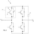
- FIG. 2 is a schematic showing components of the power switching assembly of FIG. 1 , arranged in a full bridge configuration.
- FIG. 3 illustrates three phases of a power transmission system, each phase including the installation of a bank of impedance injection modules, in accordance with an embodiment of the present invention.
- FIG. 4 is a schematic illustration of a power flow control system deployed in a mobile configuration, in accordance with the present invention.
- FIG. 5 is a flow chart that illustrates planning blocks for installing an agile power flow control system, in accordance with an embodiment of the present invention.
- FIG. 1 is a block diagram of an impedance injection module 10 having a wireless interface 1 to a support system 2 , which provides configuration parameters to impedance injection module 10 in accordance with a system-level plan to optimize power flow in a transmission line of a high voltage power transmission system, as well as reconfiguration parameters as power flow characteristics vary with changing power source and load conditions and/or on redeployment of the impedance injection module.
- configuration and reconfiguration parameters may be provided wirelessly through the support system 2 of FIG. 1 , thereby allowing the parameters to be as frequently updated as desired without physical access to the modules.
- Impedance injection module 10 includes a communication and control block 3 which comprises an antenna 4 for receiving and transmitting wireless signals 1 , a transceiver 5 coupled to antenna 4 , and a microprocessor 6 coupled to the transceiver 5 and to a memory 7 .
- Memory 7 contains instructions executable by microprocessor 6 for operating impedance injection module 10 , including transmission of configuration parameters to power switching assembly 8 , to be further described in reference to FIGS. 2-3 .
- Memory 7 also includes a nonvolatile rewrite section that may be programed (data and/or instructions) by the support system 2 through transceiver 5 as software configuration programming to configure, and reconfigure as necessary, each of the individual impedance injection modules 10 as previously described.
- impedance injection module 10 may be configured or reconfigured and controlled as required, by a remote support system 2 as desired.
- Impedance injection module 10 may further include elements that are not shown, such as by way of example, a battery, heat dissipation elements, and discrete filter components.
- each of the impedance injection modules is configurable to adjust line reactance while having a smaller effect on line resistance.
- FIG. 2 is a circuit schematic for power switching assembly 8 , implemented as a full bridge in an exemplary embodiment of an impedance injection module of the present invention.
- Terminals 21 and 22 connect in series with the transmission line as shown in FIG. 3 as connections 21 b and 22 b for the B phase of the transmission lines.
- Device 23 includes a high-power switch 24 with a control input 25 , the control value to be determined by the microprocessor 6 in each impedance injection module 10 .
- the control input is a one bit digital value per power switching device 23 that is subsequently amplified to drive each power switching device 23 at their respective control inputs 25 .
- the high-power switch 24 depicted is an insulated gate bipolar transistor (IGBT). However, a thyristor, a metal oxide semiconductor field effect transistors (MOSFET), a gate turn-off thyristor (GTO) or other power switching device may be used.
- the high-power switches 24 may employ silicon, silicon carbide, or gallium nitride semiconductors as non-limiting examples.
- Diodes 26 are body (or substrate) to drain diodes in each high-power switch 24 ( FIG. 2 ) of each impedance injection module 10 .
- a DC link capacitor 27 stores the DC voltage that is required to be injected. Note that using the full bridge implementation of power switching assembly 8 , each full bridge 8 in each impedance injection module 10 can be activated to store on the link capacitor 27 a DC voltage of either polarity and inject the DC voltage stored on link capacitor 27 at the appropriate times and with the desired polarity within one cycle of the line current waveform. The DC voltage stored on link capacitor 27 can be instantaneously reduced as required by turning on a pair of the high-power switches 24 at the correct moment in a power cycle. In some embodiments, a half-bridge converter may be used in place of a full bridge. The impedance injection may be capacitive or inductive as needed or desired by appropriate control of switching devices 23 ( FIG. 2 ).
- FIG. 3 depicts a power flow control system 30 a in an embodiment of the present invention.
- Power flow control system 30 a may be described as a bank of transformerless static synchronous series converters (TL-SSSC), described herein as transformerless converters, each in the form of an impedance injection module 10 that injects a pre-determined (controllable) waveform onto a phase of a power transmission system wherein the waveform is synchronous with the line current, and wherein the transformerless converter comprises stationary (static, non-moving or non-rotating) equipment, and also comprises components connected in series with the line.
- TL-SSSC transformerless static synchronous series converters
- Three phases labeled A, B, C are shown, representing three power transmission lines of a high voltage power transmission system forming a part of the grid and carrying electrical power from a three-phase power source 31 , each phase carrying an identical power flow control system 30 a , 30 b , 30 c .
- Power source 31 may be a substation for example, or some other power source, such as a mechanical power generator, a solar farm, etc.
- Phase A includes X AU 33 a , the upstream impedance of the transmission line, and carries an electric current I A 34 , shown as a vector quantity having both magnitude and direction.
- X AD 33 b is the downstream impedance of the transmission line.
- I A may be represented as a sine wave versus time, having an amplitude and an instantaneous phase angle.
- a bank 35 of impedance injection modules 10 is shown, configured as an m ⁇ n matrix of impedance injection modules, wherein each impedance injection module is capable of impressing a synthesized impedance to the current flowing on line A 32 , I A 34 .
- Each impedance injection module 10 impresses the synthesized impedance across terminals such as 21 b and 22 b in phase B of the figure, where terminals 21 and 22 are defined in reference to FIG. 2 .
- Variables m 36 and n 37 are each an integer in a typical range of 1-2,000, allowing for application to power transmission systems across a broad range of operating voltages and currents, while improving the efficiency of power transmission through power flow control system 30 a .
- m equals the number of impedance injection modules in series in a leg of the bank of impedance injection modules.
- n equals the number of parallel legs in the bank of impedance injection modules.
- m equals the number of impedance injection modules in series in a leg of the bank of impedance injection modules.
- n equals the number of parallel legs in the bank of impedance injection modules.
- each bank 35 of impedance injection modules 10 may be augmented with a bypass switch 38 , further described in cross-referenced patent application, Ser. No. 15/694,605.
- bypass switch 38 may be activated in response to a fault in a transmission line such as A, B, C, wherein the fault is external to the bank 35 of impedance injection modules 10 .
- each impedance injection module 10 in each bank 35 of impedance injection modules 10 is identical, and this standardization leads to an agile power flow control system 30 a , wherein the impedance injection modules 10 can be efficiently configured, reconfigured, and replaced if necessary.
- “identical” as used with reference to identical impedance injection modules means of the same design and construction, though may incorporate parts supplied by more than one vendor.
- each identical impedance injection module will differ from the others in such ways as having a unique serial number and electronic identification, and normally will have programming that may differ from at least some other impedance injection modules in the same power flow control system.
- the configuration and reconfiguration parameters may include parameters that include programming changes allowing the impedance injection modules to collectively be remotely coordinated to execute more than a single power flow control algorithm at different times.
- each of the plurality of impedance injection modules 10 is capable of providing an impedance injection level sufficient to optimize a reactive power transfer of at least 2 kVA per kilogram weight of the impedance injection module. Furthermore, in pursuit of a simplified yet capable power flow control system 30 a , there are no shunt components connected between the phases: there is no requirement for shunt components, and shunt components are preferably omitted in all embodiments of the present invention. Also, in power flow control system 30 a , when installed and in operation, the impedance injection modules 10 float with respect to ground and there is no requirement for a ground isolation transformer.
- the TL-SSSCs (transformerless converters) of the present invention do not require isolation from the transmission line voltage, even though the line voltage may be as high as 765 kV for example. Accordingly, transformers for either ground isolation or line voltage isolation are omitted in all embodiments of the present invention.
- isolation from ground is achieved by spacing the line around 10 meters or more above ground, by shielding the impedance injection modules within metal enclosures, and by providing corona rings (curved annular surfaces) that limit the electric field emanating from an impedance injection module. This limited electric field is insufficient to create corona discharge.
- power flow control system 30 a It is an advantage of power flow control system 30 a that it can be configured to avoid the creation of new sub-synchronous resonances arising from installation of the modular power flow control system; the power flow control system 30 a can also be configured to lessen the severity of pre-existing sub-synchronous resonances.
- Sub-synchronous resonances occur at frequencies below the primary transmission frequency which is typically 60 Hz in the United States.
- the deployment and operation of an impedance injection module includes determining the values of m and n in the one or more banks of impedance injection modules to be deployed at a specified location.
- the value of m will depend on the line impedance and the total voltage injection desired.
- the value of n will be determined by the required current capacity of each phase, given the current capacity of the individual impedance injection modules 10 .
- the advantage of splitting each phase into n legs and of placing m impedance injection modules in each leg instead of using a single leg and/or a single impedance injection module is to better facilitate the use of identical injection modules to satisfy multiple installation requirements in a much more efficient manner.
- n legs allows the application of lower current capacity impedance injection modules to meet substantially any current requirements for all phases of high current transmission lines while not providing an excessive current capacity for lower current transmission lines.
- m injection modules for each leg allows the tailoring of the voltage injection capacity to the then present requirements, again without providing excessive capacity where such capacity is not needed.
- a single injection module 10 may inject a pair of DC voltages to form a symmetric injection, with one pulse in each half cycle of the injection waveform.
- the fundamental frequency of the injected pair of positive and negative pulses will be asserted, with the remaining frequencies filtered out by the line reactance.
- FIG. 4 depicts an exemplary embodiment of a mobile power flow control system 50 of the present invention, provided on wheeled vehicles 51 and 52 .
- wheeled vehicle 51 which may be provided in plurality and the TL-SSSC impedance injection modules therein and the impedance injection modules in multiple trailers connected in series and/or parallel
- System 50 is transportable over public and private roads to a convenient site for providing power control in transmission lines 53 of a power transmission system.
- System 50 may be implemented as one or more mobile containers having the desired number of impedance injection modules set up inside, in addition to a bypass switch 38 , according to a configuration determined by the support system 2 , described in reference to FIG. 1 , and coupled together, or configured to be coupled together for a particular installation site, as schematically illustrated in FIG. 3 , for example.
- the mobile containers may have wheels as shown in FIG. 4 , or may be transportable within wheeled vehicles.
- system 50 is a dispatchable power flow control system wherein all of the components can be assembled into a tested system prior to dispatch, and not broken down for transport.
- Transmission lines 53 may connect between tower support structures such as tower support 54 upstream of system 50 , and tower support 55 downstream of system 50 .
- Bypass switch 38 is described in reference to FIG. 3 and may be transported on a separate wheeled vehicle or trailer, or could be part of each mobile unit.
- Use of a separate wheeled vehicle has the advantage that a plurality of wheeled vehicles 51 may be used in series in each transmission line 53 (or one of the parallel legs “n” in a bank 35 of impedance injection modules, FIG. 3 ), yet only a single bypass switch need be used for the series combination of wheeled vehicles.
- the synthesis of a power control waveform may be by way of cooperative control of multiple impedance injection modules 10 in multiple banks 35 of impedance injection modules 10 .
- the mobile flow control system 50 of FIG. 4 Since the mobile flow control system 50 of FIG. 4 operates in a parked location on the ground, it requires isolation from ground, in contrast with the power flow control system 30 a described in reference to FIG. 3 .
- This isolation may be provided by post insulators, string insulators, or by other methods, typically elevating the high voltage elements adequately above the ground level to provide the required isolation.
- Such elevating devices and structures may be provided as part of the wheeled vehicles 51 and 52 , by being provided by other wheeled vehicles and/or by way of preexisting, modified or erected structures for such use, with anything modified or erected for such use preferably being readily disassembleable for reconfiguring, or for transport and reassembly for redeployment at another location.
- the wheeled vehicles 51 are truck trailers specifically built or modified for the intended purpose, and may incorporate the elevating mechanisms including associated insulating pedestals for supporting and insulating the TL-SSSC modules once deployed to their operating location.
- the elevating mechanisms may be capable for elevating such devices and then turning them, or allowing them to be turned, to their angular orientation for use.
- various systems and subsystems to be deployed can be pre-configured in the trailers, and to the extent that on-site assembly and/or interconnection is necessary, all jumpers and other hardware may be prefabricated, labeled and provided in the respective wheeled vehicle transporting the devices on which the hardware will be used.
- all jumpers, etc. needed to interconnect devices on multiple wheeled vehicles, if not pre-assembled may at least be pre-fabricated to properly interconnect such devices (trailers) once the trailers are parked in the desired positions, which positions are also pre-laid out.
- the time to deploy is greatly reduced, as is the time of debugging and verifying the system once deployed.
- FIG. 5 is a flow chart 60 depicting a method for installing a modular power flow control system for optimizing power transmission on a three-phase transmission line, in an embodiment of the present invention.
- module means impedance injection module.
Landscapes
- Engineering & Computer Science (AREA)
- Power Engineering (AREA)
- Supply And Distribution Of Alternating Current (AREA)
Abstract
Description
Claims (33)
Priority Applications (3)
| Application Number | Priority Date | Filing Date | Title |
|---|---|---|---|
| US16/104,778 US10756542B2 (en) | 2018-01-26 | 2018-08-17 | Agile deployment of optimized power flow control system on the grid |
| EP19153095.5A EP3518366A3 (en) | 2018-01-26 | 2019-01-22 | Agile deployment of optimized power flow control system on the grid |
| CN201910080385.XA CN110086174B (en) | 2018-01-26 | 2019-01-28 | Modular power flow control system |
Applications Claiming Priority (2)
| Application Number | Priority Date | Filing Date | Title |
|---|---|---|---|
| US201862622441P | 2018-01-26 | 2018-01-26 | |
| US16/104,778 US10756542B2 (en) | 2018-01-26 | 2018-08-17 | Agile deployment of optimized power flow control system on the grid |
Publications (2)
| Publication Number | Publication Date |
|---|---|
| US20190237971A1 US20190237971A1 (en) | 2019-08-01 |
| US10756542B2 true US10756542B2 (en) | 2020-08-25 |
Family
ID=65200656
Family Applications (1)
| Application Number | Title | Priority Date | Filing Date |
|---|---|---|---|
| US16/104,778 Active 2039-01-28 US10756542B2 (en) | 2018-01-26 | 2018-08-17 | Agile deployment of optimized power flow control system on the grid |
Country Status (3)
| Country | Link |
|---|---|
| US (1) | US10756542B2 (en) |
| EP (1) | EP3518366A3 (en) |
| CN (1) | CN110086174B (en) |
Families Citing this family (14)
| Publication number | Priority date | Publication date | Assignee | Title |
|---|---|---|---|---|
| CN109906536B (en) * | 2016-10-12 | 2022-12-27 | 维斯塔斯风力系统集团公司 | Improvements relating to reactive power control in wind power plants |
| CA3056769C (en) * | 2017-03-17 | 2023-01-31 | Georgia Tech Research Corporation | Hybrid transformer systems and methods |
| US10998825B2 (en) * | 2018-02-12 | 2021-05-04 | The Texas A&M University System | Method and apparatus for medium-voltage electronic power conversion |
| US10396533B1 (en) * | 2018-02-22 | 2019-08-27 | Smart Wires Inc. | Containerized power flow control systems |
| WO2021013341A1 (en) * | 2019-07-23 | 2021-01-28 | Siemens Energy Global GmbH & Co. KG | Device for connecting two alternating voltage networks and method for operating the device |
| US11349310B2 (en) * | 2019-11-15 | 2022-05-31 | Smart Wires Inc. | Adaptive control technique for stability of impedance injection unit |
| US11411404B2 (en) * | 2019-11-22 | 2022-08-09 | Smart Wires Inc. | Use of the unused duration injection units in an array to reduce oscillations during impedance injection for corrections of problems |
| US11641102B2 (en) * | 2020-03-10 | 2023-05-02 | Smart Wires Inc. | Modular FACTS devices with external fault current protection within the same impedance injection module |
| EP3913786B1 (en) | 2020-05-18 | 2025-11-12 | Siemens Energy Global GmbH & Co. KG | Converter assembly with a line-commutated converter and method for starting the converter assembly |
| US11469015B2 (en) * | 2020-07-01 | 2022-10-11 | Smart Wires Inc. | Protection from and filtering of disturbances for serial connected facts |
| US20220037014A1 (en) * | 2020-07-28 | 2022-02-03 | Smart Wires Inc. | Prognostics and Diagnostics of Injection Units and Communications |
| EP3979483A1 (en) * | 2020-10-05 | 2022-04-06 | Hitachi Energy Switzerland AG | Transformer arrangement and method for voltage conversion |
| CN113098307A (en) * | 2021-04-16 | 2021-07-09 | 南京工程学院 | Series-parallel hybrid multilevel converter with energy storage function and dual phase-shifting PWM control method |
| US12349324B1 (en) * | 2021-06-16 | 2025-07-01 | Smart Wires Inc. | Direct impingement liquid cooling for static synchronous series compensator systems |
Citations (89)
| Publication number | Priority date | Publication date | Assignee | Title |
|---|---|---|---|---|
| US3955657A (en) | 1974-02-15 | 1976-05-11 | Oscar Bossi | Electric traction transportation system with storage battery powered vehicles and fast recharge at the vehicle stops |
| US3959985A (en) | 1975-02-18 | 1976-06-01 | General Electric Company | Air conditioning system for a mobile home including an interlock |
| USRE29994E (en) | 1973-02-15 | 1979-05-15 | Electric traction transportation system with storage battery powered vehicles and fast recharge at the vehicle stops | |
| US4167670A (en) | 1978-02-03 | 1979-09-11 | General Electric Company | Dental X-ray apparatus |
| US4188536A (en) | 1978-02-03 | 1980-02-12 | General Electric Company | Dental x-ray apparatus |
| US4293902A (en) | 1979-12-04 | 1981-10-06 | Ael Mirrotel, Ltd. | Transformerless fast current limiter with symetry correction for a switched-mode power supply |
| US4322817A (en) | 1980-12-29 | 1982-03-30 | Gte Automatic Electric Labs Inc. | Switching regulated pulse width modulated push-pull converter |
| US4355351A (en) | 1979-05-30 | 1982-10-19 | Schwarz Francisc C | High repetition rate power pulse generator |
| US4683461A (en) | 1985-09-17 | 1987-07-28 | Allied Corporation | Inductive magnetic field generator |
| US4823250A (en) | 1987-11-05 | 1989-04-18 | Picker International, Inc. | Electronic control for light weight, portable x-ray system |
| US4908569A (en) | 1988-08-09 | 1990-03-13 | Fest Otto P | Transformerless line powdered digital AC voltmeter |
| US5149277A (en) | 1988-07-18 | 1992-09-22 | Lemaster Dolan M | Connectivity management system |
| US5216285A (en) | 1992-02-24 | 1993-06-01 | Gunderson, Inc. | Freight car with electrical power distribution |
| US5231929A (en) | 1991-02-12 | 1993-08-03 | Franz Plasser Bahnbaumaschinen-Industriegesellschaft M.B.H. | Ballast cleaning machine with vibrator attached to track lifting unit for vibrating the unit transversely when replacing track on the ballast |
| US5270913A (en) | 1992-04-06 | 1993-12-14 | D.C. Transformation, Inc. | Compact and efficient transformerless power conversion system |
| US5340326A (en) | 1988-07-18 | 1994-08-23 | Lemaster Dolan M | Connectivity management system |
| US5741605A (en) | 1996-03-08 | 1998-04-21 | Westinghouse Electric Corporation | Solid oxide fuel cell generator with removable modular fuel cell stack configurations |
| US5875235A (en) | 1997-03-07 | 1999-02-23 | S3, Incorporated | Transformerless data access arrangement |
| US5892351A (en) | 1997-08-29 | 1999-04-06 | Compaq Computer Corporation | DC-isolated converting battery module |
| US5917779A (en) | 1997-04-16 | 1999-06-29 | Gabriel, Inc. | Transformerless LED driving circuit |
| US5949148A (en) | 1997-07-18 | 1999-09-07 | Wagner; William F. | D.C. power distribution and fuse panel unit |
| US6061259A (en) | 1999-08-30 | 2000-05-09 | Demichele; Glenn | Protected transformerless AC to DC power converter |
| US6075349A (en) | 1998-04-15 | 2000-06-13 | Mitsubishi Denki Kabushiki Kaisha | Compensation device and power transmission system using a compensation device |
| US6134105A (en) | 1998-01-06 | 2000-10-17 | Lueker; Mark David | Portable command center |
| US6198257B1 (en) | 1999-10-01 | 2001-03-06 | Metropolitan Industries, Inc. | Transformerless DC-to-AC power converter and method |
| US6296065B1 (en) | 1998-12-30 | 2001-10-02 | Black & Decker Inc. | Dual-mode non-isolated corded system for transportable cordless power tools |
| US6340851B1 (en) | 1998-03-23 | 2002-01-22 | Electric Boat Corporation | Modular transformer arrangement for use with multi-level power converter |
| US6356467B1 (en) | 1999-10-01 | 2002-03-12 | Metropolitan Industries, Inc. | DC/DC boost converter with bypass circuitry |
| US20020057342A1 (en) | 2000-11-13 | 2002-05-16 | Takashi Yoshiyama | Surveillance system |
| US6397156B1 (en) | 1998-11-17 | 2002-05-28 | Abb Inc. | Impedance measurement system for power system transmission lines |
| US6477154B1 (en) | 1997-08-14 | 2002-11-05 | Sk Telecom Co., Ltd. | Microcellular mobile communication system |
| US6489694B1 (en) | 2002-01-22 | 2002-12-03 | Jacob Chass | Ferrofluidic, electrical power generator |
| US6643566B1 (en) | 1999-01-12 | 2003-11-04 | Powerdsine Ltd. | System for power delivery over data communication cabling infrastructure |
| US20040132497A1 (en) | 2002-12-30 | 2004-07-08 | Evolium S.A.S. | VSWR-measurement with error compensation |
| US20050073200A1 (en) | 2003-10-03 | 2005-04-07 | Divan Deepakraj M. | Distributed floating series active impedances for power transmission systems |
| WO2005067117A1 (en) | 2004-01-09 | 2005-07-21 | The Circle For The Promotion Of Science And Engineering | Electric power control apparatus |
| US20050160682A1 (en) | 2002-04-04 | 2005-07-28 | Felice Quadrio | Expandable unit, in particular for houses or offices |
| US20060127715A1 (en) | 2002-10-24 | 2006-06-15 | Daimlerchrysler Ag | Layout of an electrical power system provided with a fuel cell in an electric vehicle |
| US7141894B2 (en) | 2002-11-01 | 2006-11-28 | Rudy Kraus | Apparatus for providing high quality power |
| US20070230094A1 (en) | 2006-04-04 | 2007-10-04 | Carlson Curt S | Integrated, self-contained power distribution system |
| US20070250217A1 (en) | 2006-04-25 | 2007-10-25 | Korea Electric Power Corporation | System and method for automatically operating upfc (unified power flow controller) connected to scada (supervisory control and data acquisition) |
| US20080103737A1 (en) | 2006-10-31 | 2008-05-01 | Yoon Jong-Su | Simulation system for facts connected online to scada system |
| US20080177425A1 (en) | 2005-06-24 | 2008-07-24 | Abb Research Ltd | Damping electromechanical oscillations in power systems |
| US20080205088A1 (en) | 2007-02-23 | 2008-08-28 | Shu Hung Chung | Multi-input DC/DC converters with zero-current switching |
| US7440300B2 (en) | 2005-08-29 | 2008-10-21 | Industrial Technology Research Institute | Transformerless power conversion circuit for grid-connected power generation systems |
| US7453710B2 (en) | 2006-04-26 | 2008-11-18 | Power Integrations, Inc. | Transformerless safety isolation in a power supply using safety capacitors for galvanic isolation |
| US20090173033A1 (en) | 2008-01-03 | 2009-07-09 | Robert Charles Baxter, JR. | Folding Truss System With Integrated Entertainment Technology Equipment and Method Thereof |
| US20090202241A1 (en) | 2008-02-08 | 2009-08-13 | Panasonic Avionics Corporation | Optical Communication System And Method For Distributing Content Aboard A Mobile Platform During Travel |
| US20100014322A1 (en) | 2006-09-21 | 2010-01-21 | Michael John Harrison | Switched mode power supply and method of production |
| US20100094477A1 (en) | 2006-10-05 | 2010-04-15 | Abb Research Ltd | Determination and use of power system sensitivities |
| US7729147B1 (en) | 2007-09-13 | 2010-06-01 | Henry Wong | Integrated circuit device using substrate-on-insulator for driving a load and method for fabricating the same |
| US20120024515A1 (en) | 2010-07-30 | 2012-02-02 | Hon Hai Precision Industry Co., Ltd. | Data center and heat dissipating system thereof |
| US20120085612A1 (en) | 2009-02-20 | 2012-04-12 | Churchill Frederick | Vehicle propulsion energy and utility power delivery system |
| US20120134107A1 (en) | 2010-11-17 | 2012-05-31 | Yonghui Peng | Container data center |
| US8210418B1 (en) | 2011-06-09 | 2012-07-03 | Landoll Corporation | Multi-station, gantry-based automated welding system |
| US20120205981A1 (en) | 2009-09-15 | 2012-08-16 | The University Of Western Ontario | Utilization of distributed generator inverters as statcom |
| US20120312862A1 (en) | 2011-06-09 | 2012-12-13 | Landoll Donald R | Gantry-based welding system and method |
| US20130068271A1 (en) | 2011-09-20 | 2013-03-21 | Mohammad Jamil Ahmad Bqoor | Prototype Thermoelectric Generator Based on Ionized Gas in a Container Under Electric Potential Difference |
| US20130094264A1 (en) | 2010-03-15 | 2013-04-18 | Alstom Technolgoy Ltd. | Static var compensator with multilevel converter |
| US20130128636A1 (en) | 2010-07-30 | 2013-05-23 | Alstom Technology Ltd | HVDC Converter Comprising Fullbridge Cells For Handling A DC Side Short Circuit |
| US20130155662A1 (en) | 2011-11-17 | 2013-06-20 | Eaton Industries (Austria) Gmbh | Modular Lighting System |
| US20130169055A1 (en) | 2011-12-28 | 2013-07-04 | Alstom Hydro France | Installation for producing electricity including a plurality of electricity producing devices capable of transforming mechanical energy into electric energy |
| US20130261821A1 (en) | 2011-10-04 | 2013-10-03 | Advanergy, Inc. | Power distribution system and method |
| US20130256613A1 (en) | 2012-03-30 | 2013-10-03 | Elwha LLC, a limited liabiility company of the State of Delaware | Mobile device configured to travel on a transmission line and provide assistance |
| US20130346571A1 (en) | 2012-06-24 | 2013-12-26 | Sergei MAKAVEEV | Computer and method of operation of its network |
| US20140129195A1 (en) | 2011-06-24 | 2014-05-08 | State Grid Corporation Of China | Real time dynamic physics simulation device of flexible dc transmission system |
| US20140132229A1 (en) | 2012-11-02 | 2014-05-15 | North Carolina State University | Static synchronous compensator systems and related methods |
| US8767427B2 (en) | 2011-07-19 | 2014-07-01 | Aeg Power Solutions B.V. | Arrangement for power supply for a reactor for production of polysilicon with a frequency converter |
| US20140246914A1 (en) | 2011-09-12 | 2014-09-04 | Alstom Technology Ltd. | Sub-Synchronous Oscillation Damping By Shunt Facts Apparatus |
| US20140312859A1 (en) | 2013-03-27 | 2014-10-23 | Smart Wire Grid, Inc. | Phase balancing of power transmission system |
| US20150108897A1 (en) | 2013-10-17 | 2015-04-23 | Tokyo Electron Limited | Microwave plasma processing apparatus and microwave supply method |
| US20150134137A1 (en) | 2013-11-08 | 2015-05-14 | Airbus Operations Sas | Electrical energy distribution network in a transport vehicle, such as an aircraft, and an electrical installation in an aircraft |
| US9065345B2 (en) | 2008-07-09 | 2015-06-23 | Sma Solar Technology Ag | Transformerless inverter comprising a DC/DC converter |
| US20150219554A1 (en) | 2014-01-31 | 2015-08-06 | The Boeing Company | Oxygen analysis system and method for measuring, monitoring and recording oxygen concentration in aircraft fuel tanks |
| US20150236509A1 (en) | 2011-09-16 | 2015-08-20 | Varentec, Inc. | Systems and methods for edge of network voltage control of a power grid |
| US20150293517A1 (en) | 2014-04-09 | 2015-10-15 | Adam Chase Higgins | Mobile application and control system |
| US20160036341A1 (en) | 2014-07-31 | 2016-02-04 | Korea University Research And Business Foundation | Power grid frequency flexible operation system and method using the same |
| US9332602B2 (en) | 2013-12-12 | 2016-05-03 | Genereal Electric Company | LED driver with transformerless hysteretic boost |
| US20160273211A1 (en) | 2014-10-23 | 2016-09-22 | Aruana Energia S/A | Construction device introduced into an electrical power plant module |
| US9473028B1 (en) | 2015-04-29 | 2016-10-18 | Hamilton Sundstrand Corporation | Systems and methods for controlling power converters |
| US20160369689A1 (en) | 2013-11-13 | 2016-12-22 | Aruanã Energia S/A | A modular power plant system housed within a container equipped with a transformer for connection to a local power distrbution system |
| US9590424B2 (en) | 2012-01-04 | 2017-03-07 | Coil Holding Gmbh | Device for influencing reactive-power flows |
| US20170170660A1 (en) | 2015-12-11 | 2017-06-15 | Huazhong University Of Science And Technology | Operating method of full-bridge modular multilevel converter boosting ac voltages |
| US20170237255A1 (en) | 2016-02-11 | 2017-08-17 | Smart Wires Inc. | Dynamic and Integrated Control of Total Power System Using Distributed Impedance Injection Modules and Actuator Devices Within and at the Edge of the Power Grid |
| US9847626B2 (en) | 2012-12-28 | 2017-12-19 | Prysmian S.P.A | Container based by-pass module for electric power lines |
| US20180034280A1 (en) | 2015-02-20 | 2018-02-01 | Maersk Drilling A/S | Power generation and distribution system for offshore drilling units |
| US20180316163A1 (en) | 2017-04-28 | 2018-11-01 | Lsis Co., Ltd. | Submodule |
| US10141724B2 (en) | 2017-04-28 | 2018-11-27 | Lsis Co., Ltd. | Apparatus of sliding submodule |
| US20190006835A1 (en) | 2017-06-30 | 2019-01-03 | Smart Wires Inc. | Modular FACTS Devices with External Fault Current Protection |
Family Cites Families (1)
| Publication number | Priority date | Publication date | Assignee | Title |
|---|---|---|---|---|
| CN100511910C (en) * | 2007-07-31 | 2009-07-08 | 湖南大学 | Current and DC side voltage control method for injected mixed active power filter |
-
2018
- 2018-08-17 US US16/104,778 patent/US10756542B2/en active Active
-
2019
- 2019-01-22 EP EP19153095.5A patent/EP3518366A3/en active Pending
- 2019-01-28 CN CN201910080385.XA patent/CN110086174B/en active Active
Patent Citations (113)
| Publication number | Priority date | Publication date | Assignee | Title |
|---|---|---|---|---|
| USRE29994E (en) | 1973-02-15 | 1979-05-15 | Electric traction transportation system with storage battery powered vehicles and fast recharge at the vehicle stops | |
| US3955657A (en) | 1974-02-15 | 1976-05-11 | Oscar Bossi | Electric traction transportation system with storage battery powered vehicles and fast recharge at the vehicle stops |
| US3959985A (en) | 1975-02-18 | 1976-06-01 | General Electric Company | Air conditioning system for a mobile home including an interlock |
| US4167670A (en) | 1978-02-03 | 1979-09-11 | General Electric Company | Dental X-ray apparatus |
| US4188536A (en) | 1978-02-03 | 1980-02-12 | General Electric Company | Dental x-ray apparatus |
| US4355351A (en) | 1979-05-30 | 1982-10-19 | Schwarz Francisc C | High repetition rate power pulse generator |
| US4293902A (en) | 1979-12-04 | 1981-10-06 | Ael Mirrotel, Ltd. | Transformerless fast current limiter with symetry correction for a switched-mode power supply |
| US4322817A (en) | 1980-12-29 | 1982-03-30 | Gte Automatic Electric Labs Inc. | Switching regulated pulse width modulated push-pull converter |
| US4683461A (en) | 1985-09-17 | 1987-07-28 | Allied Corporation | Inductive magnetic field generator |
| US4823250A (en) | 1987-11-05 | 1989-04-18 | Picker International, Inc. | Electronic control for light weight, portable x-ray system |
| US5149277A (en) | 1988-07-18 | 1992-09-22 | Lemaster Dolan M | Connectivity management system |
| US5340326A (en) | 1988-07-18 | 1994-08-23 | Lemaster Dolan M | Connectivity management system |
| US4908569A (en) | 1988-08-09 | 1990-03-13 | Fest Otto P | Transformerless line powdered digital AC voltmeter |
| US5231929A (en) | 1991-02-12 | 1993-08-03 | Franz Plasser Bahnbaumaschinen-Industriegesellschaft M.B.H. | Ballast cleaning machine with vibrator attached to track lifting unit for vibrating the unit transversely when replacing track on the ballast |
| US5216285A (en) | 1992-02-24 | 1993-06-01 | Gunderson, Inc. | Freight car with electrical power distribution |
| US5270913A (en) | 1992-04-06 | 1993-12-14 | D.C. Transformation, Inc. | Compact and efficient transformerless power conversion system |
| US5741605A (en) | 1996-03-08 | 1998-04-21 | Westinghouse Electric Corporation | Solid oxide fuel cell generator with removable modular fuel cell stack configurations |
| US5875235A (en) | 1997-03-07 | 1999-02-23 | S3, Incorporated | Transformerless data access arrangement |
| US5917779A (en) | 1997-04-16 | 1999-06-29 | Gabriel, Inc. | Transformerless LED driving circuit |
| US5949148A (en) | 1997-07-18 | 1999-09-07 | Wagner; William F. | D.C. power distribution and fuse panel unit |
| US6477154B1 (en) | 1997-08-14 | 2002-11-05 | Sk Telecom Co., Ltd. | Microcellular mobile communication system |
| US5892351A (en) | 1997-08-29 | 1999-04-06 | Compaq Computer Corporation | DC-isolated converting battery module |
| US6134105A (en) | 1998-01-06 | 2000-10-17 | Lueker; Mark David | Portable command center |
| US6340851B1 (en) | 1998-03-23 | 2002-01-22 | Electric Boat Corporation | Modular transformer arrangement for use with multi-level power converter |
| US6075349A (en) | 1998-04-15 | 2000-06-13 | Mitsubishi Denki Kabushiki Kaisha | Compensation device and power transmission system using a compensation device |
| US6397156B1 (en) | 1998-11-17 | 2002-05-28 | Abb Inc. | Impedance measurement system for power system transmission lines |
| US6460626B2 (en) | 1998-12-30 | 2002-10-08 | Black & Decker Inc. | Dual-mode non-isolated corded system for transportable cordless power tools |
| US6296065B1 (en) | 1998-12-30 | 2001-10-02 | Black & Decker Inc. | Dual-mode non-isolated corded system for transportable cordless power tools |
| US6675912B2 (en) | 1998-12-30 | 2004-01-13 | Black & Decker Inc. | Dual-mode non-isolated corded system for transportable cordless power tools |
| US7466819B2 (en) | 1999-01-12 | 2008-12-16 | Microsemi Corp. | System for powering a switch over data communication cabling infrastructure |
| US20050169243A1 (en) | 1999-01-12 | 2005-08-04 | Amir Lehr | Combiner for power delivery over data communication cabling infrastructure |
| US6643566B1 (en) | 1999-01-12 | 2003-11-04 | Powerdsine Ltd. | System for power delivery over data communication cabling infrastructure |
| US20040049321A1 (en) | 1999-01-12 | 2004-03-11 | Amir Lehr | System for power delivery over data communication cabling infrastructure |
| US6909943B2 (en) | 1999-01-12 | 2005-06-21 | Power Dsine, Ltd. | System for power delivery over data communication cabling infrastructure |
| US7325150B2 (en) | 1999-01-12 | 2008-01-29 | Microsemi Corp.—Analog Mixed Signal Group, Ltd. | Combiner for power delivery over data communication cabling infrastructure |
| US20050169297A1 (en) | 1999-01-12 | 2005-08-04 | Amir Lehr | System for powering a switch over data communication cabling infrastructure |
| US6061259A (en) | 1999-08-30 | 2000-05-09 | Demichele; Glenn | Protected transformerless AC to DC power converter |
| US6198257B1 (en) | 1999-10-01 | 2001-03-06 | Metropolitan Industries, Inc. | Transformerless DC-to-AC power converter and method |
| US6356467B1 (en) | 1999-10-01 | 2002-03-12 | Metropolitan Industries, Inc. | DC/DC boost converter with bypass circuitry |
| US20020057342A1 (en) | 2000-11-13 | 2002-05-16 | Takashi Yoshiyama | Surveillance system |
| US6489694B1 (en) | 2002-01-22 | 2002-12-03 | Jacob Chass | Ferrofluidic, electrical power generator |
| US20050160682A1 (en) | 2002-04-04 | 2005-07-28 | Felice Quadrio | Expandable unit, in particular for houses or offices |
| US7469759B2 (en) | 2002-10-24 | 2008-12-30 | Daimler Ag | Layout of an electrical power system provided with a fuel cell in an electric vehicle |
| US20060127715A1 (en) | 2002-10-24 | 2006-06-15 | Daimlerchrysler Ag | Layout of an electrical power system provided with a fuel cell in an electric vehicle |
| US7141894B2 (en) | 2002-11-01 | 2006-11-28 | Rudy Kraus | Apparatus for providing high quality power |
| US20040132497A1 (en) | 2002-12-30 | 2004-07-08 | Evolium S.A.S. | VSWR-measurement with error compensation |
| US20050073200A1 (en) | 2003-10-03 | 2005-04-07 | Divan Deepakraj M. | Distributed floating series active impedances for power transmission systems |
| WO2005067117A1 (en) | 2004-01-09 | 2005-07-21 | The Circle For The Promotion Of Science And Engineering | Electric power control apparatus |
| US8019484B2 (en) | 2005-06-24 | 2011-09-13 | Abb Research Ltd | Damping electromechanical oscillations in power systems |
| US20080177425A1 (en) | 2005-06-24 | 2008-07-24 | Abb Research Ltd | Damping electromechanical oscillations in power systems |
| US7440300B2 (en) | 2005-08-29 | 2008-10-21 | Industrial Technology Research Institute | Transformerless power conversion circuit for grid-connected power generation systems |
| US20070230094A1 (en) | 2006-04-04 | 2007-10-04 | Carlson Curt S | Integrated, self-contained power distribution system |
| US20070250217A1 (en) | 2006-04-25 | 2007-10-25 | Korea Electric Power Corporation | System and method for automatically operating upfc (unified power flow controller) connected to scada (supervisory control and data acquisition) |
| US7642757B2 (en) | 2006-04-25 | 2010-01-05 | Korea Electric Power Corporation | System and method for automatically operating UPFC (unified power flow controller) connected to SCADA (supervisory control and data acquisition) |
| US7453710B2 (en) | 2006-04-26 | 2008-11-18 | Power Integrations, Inc. | Transformerless safety isolation in a power supply using safety capacitors for galvanic isolation |
| US20100014322A1 (en) | 2006-09-21 | 2010-01-21 | Michael John Harrison | Switched mode power supply and method of production |
| US8395916B2 (en) | 2006-09-21 | 2013-03-12 | Eaton Industries Company | Switched mode power supply and method of production |
| US20100094477A1 (en) | 2006-10-05 | 2010-04-15 | Abb Research Ltd | Determination and use of power system sensitivities |
| US20080103737A1 (en) | 2006-10-31 | 2008-05-01 | Yoon Jong-Su | Simulation system for facts connected online to scada system |
| US8249836B2 (en) | 2006-10-31 | 2012-08-21 | Korea Electric Power Corporation | Simulation system for FACTS connected online to SCADA system |
| US20080205088A1 (en) | 2007-02-23 | 2008-08-28 | Shu Hung Chung | Multi-input DC/DC converters with zero-current switching |
| US8189351B2 (en) | 2007-02-23 | 2012-05-29 | Astec International Limited | Multi-input DC/DC converters with zero-current switching |
| US7729147B1 (en) | 2007-09-13 | 2010-06-01 | Henry Wong | Integrated circuit device using substrate-on-insulator for driving a load and method for fabricating the same |
| US20090173033A1 (en) | 2008-01-03 | 2009-07-09 | Robert Charles Baxter, JR. | Folding Truss System With Integrated Entertainment Technology Equipment and Method Thereof |
| US20090202241A1 (en) | 2008-02-08 | 2009-08-13 | Panasonic Avionics Corporation | Optical Communication System And Method For Distributing Content Aboard A Mobile Platform During Travel |
| US9065345B2 (en) | 2008-07-09 | 2015-06-23 | Sma Solar Technology Ag | Transformerless inverter comprising a DC/DC converter |
| US20120085612A1 (en) | 2009-02-20 | 2012-04-12 | Churchill Frederick | Vehicle propulsion energy and utility power delivery system |
| US20120205981A1 (en) | 2009-09-15 | 2012-08-16 | The University Of Western Ontario | Utilization of distributed generator inverters as statcom |
| US9325173B2 (en) | 2009-09-15 | 2016-04-26 | The University Of Western Ontario | Utilization of distributed generator inverters as STATCOM |
| US20130094264A1 (en) | 2010-03-15 | 2013-04-18 | Alstom Technolgoy Ltd. | Static var compensator with multilevel converter |
| US9130458B2 (en) | 2010-03-15 | 2015-09-08 | Alstom Technology Ltd. | Static VAR compensator with multilevel converter |
| US20130128636A1 (en) | 2010-07-30 | 2013-05-23 | Alstom Technology Ltd | HVDC Converter Comprising Fullbridge Cells For Handling A DC Side Short Circuit |
| US8867244B2 (en) | 2010-07-30 | 2014-10-21 | Alstom Technology Ltd. | HVDC converter including fullbridge cells for handling a DC side short circuit |
| US20120024515A1 (en) | 2010-07-30 | 2012-02-02 | Hon Hai Precision Industry Co., Ltd. | Data center and heat dissipating system thereof |
| US20120134107A1 (en) | 2010-11-17 | 2012-05-31 | Yonghui Peng | Container data center |
| US8755184B2 (en) | 2010-11-17 | 2014-06-17 | Huawei Technologies Co., Ltd. | Container data center |
| US8434657B2 (en) | 2011-06-09 | 2013-05-07 | Landoll Corporation | Gantry-based welding system and method |
| US8210418B1 (en) | 2011-06-09 | 2012-07-03 | Landoll Corporation | Multi-station, gantry-based automated welding system |
| US20120312862A1 (en) | 2011-06-09 | 2012-12-13 | Landoll Donald R | Gantry-based welding system and method |
| US9659114B2 (en) | 2011-06-24 | 2017-05-23 | State Grid Corporation Of China | Real time dynamic physics simulation device of flexible DC transmission system |
| US20140129195A1 (en) | 2011-06-24 | 2014-05-08 | State Grid Corporation Of China | Real time dynamic physics simulation device of flexible dc transmission system |
| US8767427B2 (en) | 2011-07-19 | 2014-07-01 | Aeg Power Solutions B.V. | Arrangement for power supply for a reactor for production of polysilicon with a frequency converter |
| US20140246914A1 (en) | 2011-09-12 | 2014-09-04 | Alstom Technology Ltd. | Sub-Synchronous Oscillation Damping By Shunt Facts Apparatus |
| US20150236509A1 (en) | 2011-09-16 | 2015-08-20 | Varentec, Inc. | Systems and methods for edge of network voltage control of a power grid |
| US20130068271A1 (en) | 2011-09-20 | 2013-03-21 | Mohammad Jamil Ahmad Bqoor | Prototype Thermoelectric Generator Based on Ionized Gas in a Container Under Electric Potential Difference |
| US8649883B2 (en) | 2011-10-04 | 2014-02-11 | Advanergy, Inc. | Power distribution system and method |
| US20130261821A1 (en) | 2011-10-04 | 2013-10-03 | Advanergy, Inc. | Power distribution system and method |
| US20130155662A1 (en) | 2011-11-17 | 2013-06-20 | Eaton Industries (Austria) Gmbh | Modular Lighting System |
| US20130169055A1 (en) | 2011-12-28 | 2013-07-04 | Alstom Hydro France | Installation for producing electricity including a plurality of electricity producing devices capable of transforming mechanical energy into electric energy |
| US9590424B2 (en) | 2012-01-04 | 2017-03-07 | Coil Holding Gmbh | Device for influencing reactive-power flows |
| US20130256613A1 (en) | 2012-03-30 | 2013-10-03 | Elwha LLC, a limited liabiility company of the State of Delaware | Mobile device configured to travel on a transmission line and provide assistance |
| US20130346571A1 (en) | 2012-06-24 | 2013-12-26 | Sergei MAKAVEEV | Computer and method of operation of its network |
| US20140132229A1 (en) | 2012-11-02 | 2014-05-15 | North Carolina State University | Static synchronous compensator systems and related methods |
| US9331482B2 (en) | 2012-11-02 | 2016-05-03 | North Carolina State University | Static synchronous compensator systems and related methods |
| US9847626B2 (en) | 2012-12-28 | 2017-12-19 | Prysmian S.P.A | Container based by-pass module for electric power lines |
| US20140312859A1 (en) | 2013-03-27 | 2014-10-23 | Smart Wire Grid, Inc. | Phase balancing of power transmission system |
| US20150108897A1 (en) | 2013-10-17 | 2015-04-23 | Tokyo Electron Limited | Microwave plasma processing apparatus and microwave supply method |
| US9241397B2 (en) | 2013-10-17 | 2016-01-19 | Tokyo Electron Limited | Microwave plasma processing apparatus and microwave supply method |
| US20150134137A1 (en) | 2013-11-08 | 2015-05-14 | Airbus Operations Sas | Electrical energy distribution network in a transport vehicle, such as an aircraft, and an electrical installation in an aircraft |
| US20160369689A1 (en) | 2013-11-13 | 2016-12-22 | Aruanã Energia S/A | A modular power plant system housed within a container equipped with a transformer for connection to a local power distrbution system |
| US9332602B2 (en) | 2013-12-12 | 2016-05-03 | Genereal Electric Company | LED driver with transformerless hysteretic boost |
| US20150219554A1 (en) | 2014-01-31 | 2015-08-06 | The Boeing Company | Oxygen analysis system and method for measuring, monitoring and recording oxygen concentration in aircraft fuel tanks |
| US20150293517A1 (en) | 2014-04-09 | 2015-10-15 | Adam Chase Higgins | Mobile application and control system |
| US20160036341A1 (en) | 2014-07-31 | 2016-02-04 | Korea University Research And Business Foundation | Power grid frequency flexible operation system and method using the same |
| US20160273211A1 (en) | 2014-10-23 | 2016-09-22 | Aruana Energia S/A | Construction device introduced into an electrical power plant module |
| US20180034280A1 (en) | 2015-02-20 | 2018-02-01 | Maersk Drilling A/S | Power generation and distribution system for offshore drilling units |
| US9473028B1 (en) | 2015-04-29 | 2016-10-18 | Hamilton Sundstrand Corporation | Systems and methods for controlling power converters |
| US9735702B2 (en) | 2015-12-11 | 2017-08-15 | Huazhong University Of Science And Technology | Operating method of full-bridge modular multilevel converter boosting AC voltages for high voltage direct current transmission |
| US20170170660A1 (en) | 2015-12-11 | 2017-06-15 | Huazhong University Of Science And Technology | Operating method of full-bridge modular multilevel converter boosting ac voltages |
| US20170237255A1 (en) | 2016-02-11 | 2017-08-17 | Smart Wires Inc. | Dynamic and Integrated Control of Total Power System Using Distributed Impedance Injection Modules and Actuator Devices Within and at the Edge of the Power Grid |
| US20180316163A1 (en) | 2017-04-28 | 2018-11-01 | Lsis Co., Ltd. | Submodule |
| US10141724B2 (en) | 2017-04-28 | 2018-11-27 | Lsis Co., Ltd. | Apparatus of sliding submodule |
| US20190006835A1 (en) | 2017-06-30 | 2019-01-03 | Smart Wires Inc. | Modular FACTS Devices with External Fault Current Protection |
Non-Patent Citations (9)
Also Published As
| Publication number | Publication date |
|---|---|
| CN110086174A (en) | 2019-08-02 |
| EP3518366A3 (en) | 2019-10-09 |
| CN110086174B (en) | 2024-03-26 |
| US20190237971A1 (en) | 2019-08-01 |
| EP3518366A2 (en) | 2019-07-31 |
Similar Documents
| Publication | Publication Date | Title |
|---|---|---|
| US10756542B2 (en) | Agile deployment of optimized power flow control system on the grid | |
| US9276474B2 (en) | Power conversion system with controlled neutral | |
| US10637371B2 (en) | Interface arrangement between an alternating current power system and a direct current power system with control of converter valve for fault protection | |
| KR101670309B1 (en) | Converter | |
| US10523132B2 (en) | Start-up of HVDC converters | |
| US8779730B2 (en) | Capacitor discharge in a cell based voltage source converter | |
| JP2007507999A (en) | Distributed floating series active impedance for power transmission systems. | |
| AU2011201307A1 (en) | DC transmission system for remote solar farms | |
| US9853562B2 (en) | Converter station with diode rectifier | |
| US10700597B1 (en) | Distribution transformer power flow controller | |
| Dworakowski et al. | Linear PV power plant based on MVDC collection network | |
| CN110710089B (en) | Grounding Arrangements for Voltage Source Converters | |
| AU2019204500A1 (en) | Agile deployment of optimized power flow control system on the grid | |
| US10770870B2 (en) | Containerized power flow control systems | |
| US11444553B2 (en) | Electrical power conversion system and associated method | |
| Tanaka et al. | Reactive power compensation capability of a STATCOM based on two types of Modular Multilevel Cascade Converters for offshore wind application | |
| EP3142239A1 (en) | Precharging of a modular multilevel converter | |
| Berne et al. | Earth currents in HVDC grids: An example based on 5 terminal bipolar configurations | |
| ES2866178T3 (en) | Commutator, distributor system and method of adjusting the unbalance of the current or the voltages from phase to neutral | |
| US20250373018A1 (en) | Variable VAR Module | |
| EP3534523B1 (en) | Improvements in or relating to hvdc power converters | |
| CN113056854B (en) | STATCOM device without phase reactor | |
| Bisewski et al. | HVDC Terminology, Symbols, Definitions and Abbreviations | |
| CN111108290A (en) | Hybrid power generation system and associated method |
Legal Events
| Date | Code | Title | Description |
|---|---|---|---|
| FEPP | Fee payment procedure |
Free format text: ENTITY STATUS SET TO UNDISCOUNTED (ORIGINAL EVENT CODE: BIG.); ENTITY STATUS OF PATENT OWNER: SMALL ENTITY |
|
| AS | Assignment |
Owner name: SMART WIRES INC., CALIFORNIA Free format text: ASSIGNMENT OF ASSIGNORS INTEREST;ASSIGNORS:INAM, HAROON;DAS, DEBRUP;IYER, AMRIT;AND OTHERS;SIGNING DATES FROM 20150102 TO 20180803;REEL/FRAME:046735/0629 |
|
| FEPP | Fee payment procedure |
Free format text: ENTITY STATUS SET TO SMALL (ORIGINAL EVENT CODE: SMAL); ENTITY STATUS OF PATENT OWNER: SMALL ENTITY |
|
| AS | Assignment |
Owner name: SMART WIRES INC., CALIFORNIA Free format text: ASSIGNMENT OF ASSIGNORS INTEREST;ASSIGNOR:DAS, DEBRUP;REEL/FRAME:046864/0796 Effective date: 20180829 |
|
| AS | Assignment |
Owner name: SMART WIRES CREDIT FACILITY, LLC, OREGON Free format text: SECURITY AGREEMENT;ASSIGNOR:SMART WIRES INC.;REEL/FRAME:049951/0548 Effective date: 20190215 |
|
| STPP | Information on status: patent application and granting procedure in general |
Free format text: NOTICE OF ALLOWANCE MAILED -- APPLICATION RECEIVED IN OFFICE OF PUBLICATIONS |
|
| STPP | Information on status: patent application and granting procedure in general |
Free format text: AWAITING TC RESP., ISSUE FEE NOT PAID |
|
| AS | Assignment |
Owner name: BLUE TORCH FINANCE LLC, AS COLLATERAL AGENT, NEW YORK Free format text: SECURITY INTEREST;ASSIGNOR:SMART WIRES INC.;REEL/FRAME:053000/0025 Effective date: 20200622 |
|
| AS | Assignment |
Owner name: SMART WIRES INC., CALIFORNIA Free format text: RELEASE BY SECURED PARTY;ASSIGNOR:SMART WIRES CREDIT FACILITY, LLC;REEL/FRAME:053017/0985 Effective date: 20200622 |
|
| STCF | Information on status: patent grant |
Free format text: PATENTED CASE |
|
| AS | Assignment |
Owner name: SMART WIRES INC., CALIFORNIA Free format text: RELEASE AND TERMINATION OF SECURITY INTEREST IN PATENT COLLATERAL;ASSIGNOR:BLUE TORCH FINANCE LLC;REEL/FRAME:056423/0448 Effective date: 20210521 |
|
| AS | Assignment |
Owner name: INNOVATUS LIFE SCIENCES LENDING FUND I, LP, NEW YORK Free format text: INTELLECTUAL PROPERTY SECURITYAGREEMENT;ASSIGNOR:SMART WIRES INC.;REEL/FRAME:058653/0190 Effective date: 20211231 |
|
| MAFP | Maintenance fee payment |
Free format text: PAYMENT OF MAINTENANCE FEE, 4TH YR, SMALL ENTITY (ORIGINAL EVENT CODE: M2551); ENTITY STATUS OF PATENT OWNER: SMALL ENTITY Year of fee payment: 4 |