US10751923B2 - Spark plug insulator production method, insulator, molding die - Google Patents
Spark plug insulator production method, insulator, molding die Download PDFInfo
- Publication number
- US10751923B2 US10751923B2 US15/534,529 US201515534529A US10751923B2 US 10751923 B2 US10751923 B2 US 10751923B2 US 201515534529 A US201515534529 A US 201515534529A US 10751923 B2 US10751923 B2 US 10751923B2
- Authority
- US
- United States
- Prior art keywords
- mold
- internal surface
- insulator
- mold piece
- piece
- Prior art date
- Legal status (The legal status is an assumption and is not a legal conclusion. Google has not performed a legal analysis and makes no representation as to the accuracy of the status listed.)
- Expired - Fee Related, expires
Links
Images


Classifications
-
- B—PERFORMING OPERATIONS; TRANSPORTING
- B29—WORKING OF PLASTICS; WORKING OF SUBSTANCES IN A PLASTIC STATE IN GENERAL
- B29C—SHAPING OR JOINING OF PLASTICS; SHAPING OF MATERIAL IN A PLASTIC STATE, NOT OTHERWISE PROVIDED FOR; AFTER-TREATMENT OF THE SHAPED PRODUCTS, e.g. REPAIRING
- B29C45/00—Injection moulding, i.e. forcing the required volume of moulding material through a nozzle into a closed mould; Apparatus therefor
- B29C45/14—Injection moulding, i.e. forcing the required volume of moulding material through a nozzle into a closed mould; Apparatus therefor incorporating preformed parts or layers, e.g. injection moulding around inserts or for coating articles
- B29C45/14639—Injection moulding, i.e. forcing the required volume of moulding material through a nozzle into a closed mould; Apparatus therefor incorporating preformed parts or layers, e.g. injection moulding around inserts or for coating articles for obtaining an insulating effect, e.g. for electrical components
- B29C45/14655—Injection moulding, i.e. forcing the required volume of moulding material through a nozzle into a closed mould; Apparatus therefor incorporating preformed parts or layers, e.g. injection moulding around inserts or for coating articles for obtaining an insulating effect, e.g. for electrical components connected to or mounted on a carrier, e.g. lead frame
-
- B—PERFORMING OPERATIONS; TRANSPORTING
- B28—WORKING CEMENT, CLAY, OR STONE
- B28B—SHAPING CLAY OR OTHER CERAMIC COMPOSITIONS; SHAPING SLAG; SHAPING MIXTURES CONTAINING CEMENTITIOUS MATERIAL, e.g. PLASTER
- B28B1/00—Producing shaped prefabricated articles from the material
- B28B1/24—Producing shaped prefabricated articles from the material by injection moulding
-
- B—PERFORMING OPERATIONS; TRANSPORTING
- B28—WORKING CEMENT, CLAY, OR STONE
- B28B—SHAPING CLAY OR OTHER CERAMIC COMPOSITIONS; SHAPING SLAG; SHAPING MIXTURES CONTAINING CEMENTITIOUS MATERIAL, e.g. PLASTER
- B28B13/00—Feeding the unshaped material to moulds or apparatus for producing shaped articles; Discharging shaped articles from such moulds or apparatus
- B28B13/04—Discharging the shaped articles
- B28B13/06—Removing the shaped articles from moulds
-
- B—PERFORMING OPERATIONS; TRANSPORTING
- B28—WORKING CEMENT, CLAY, OR STONE
- B28B—SHAPING CLAY OR OTHER CERAMIC COMPOSITIONS; SHAPING SLAG; SHAPING MIXTURES CONTAINING CEMENTITIOUS MATERIAL, e.g. PLASTER
- B28B7/00—Moulds; Cores; Mandrels
- B28B7/0029—Moulds or moulding surfaces not covered by B28B7/0058 - B28B7/36 and B28B7/40 - B28B7/465, e.g. moulds assembled from several parts
- B28B7/0035—Moulds characterised by the way in which the sidewalls of the mould and the moulded article move with respect to each other during demoulding
- B28B7/0038—Moulds characterised by the way in which the sidewalls of the mould and the moulded article move with respect to each other during demoulding the sidewalls of mould and moulded article moving only past each other, e.g. box-shaped moulds which are lifted off from the moulding
-
- B—PERFORMING OPERATIONS; TRANSPORTING
- B28—WORKING CEMENT, CLAY, OR STONE
- B28B—SHAPING CLAY OR OTHER CERAMIC COMPOSITIONS; SHAPING SLAG; SHAPING MIXTURES CONTAINING CEMENTITIOUS MATERIAL, e.g. PLASTER
- B28B7/00—Moulds; Cores; Mandrels
- B28B7/16—Moulds for making shaped articles with cavities or holes open to the surface, e.g. with blind holes
- B28B7/18—Moulds for making shaped articles with cavities or holes open to the surface, e.g. with blind holes the holes passing completely through the article
-
- B—PERFORMING OPERATIONS; TRANSPORTING
- B28—WORKING CEMENT, CLAY, OR STONE
- B28B—SHAPING CLAY OR OTHER CERAMIC COMPOSITIONS; SHAPING SLAG; SHAPING MIXTURES CONTAINING CEMENTITIOUS MATERIAL, e.g. PLASTER
- B28B7/00—Moulds; Cores; Mandrels
- B28B7/34—Moulds, cores, or mandrels of special material, e.g. destructible materials
- B28B7/346—Manufacture of moulds
-
- H—ELECTRICITY
- H01—ELECTRIC ELEMENTS
- H01T—SPARK GAPS; OVERVOLTAGE ARRESTERS USING SPARK GAPS; SPARKING PLUGS; CORONA DEVICES; GENERATING IONS TO BE INTRODUCED INTO NON-ENCLOSED GASES
- H01T13/00—Sparking plugs
- H01T13/20—Sparking plugs characterised by features of the electrodes or insulation
-
- H—ELECTRICITY
- H01—ELECTRIC ELEMENTS
- H01T—SPARK GAPS; OVERVOLTAGE ARRESTERS USING SPARK GAPS; SPARKING PLUGS; CORONA DEVICES; GENERATING IONS TO BE INTRODUCED INTO NON-ENCLOSED GASES
- H01T21/00—Apparatus or processes specially adapted for the manufacture or maintenance of spark gaps or sparking plugs
- H01T21/02—Apparatus or processes specially adapted for the manufacture or maintenance of spark gaps or sparking plugs of sparking plugs
-
- H—ELECTRICITY
- H01—ELECTRIC ELEMENTS
- H01T—SPARK GAPS; OVERVOLTAGE ARRESTERS USING SPARK GAPS; SPARKING PLUGS; CORONA DEVICES; GENERATING IONS TO BE INTRODUCED INTO NON-ENCLOSED GASES
- H01T13/00—Sparking plugs
- H01T13/20—Sparking plugs characterised by features of the electrodes or insulation
- H01T13/34—Sparking plugs characterised by features of the electrodes or insulation characterised by the mounting of electrodes in insulation, e.g. by embedding
-
- H—ELECTRICITY
- H01—ELECTRIC ELEMENTS
- H01T—SPARK GAPS; OVERVOLTAGE ARRESTERS USING SPARK GAPS; SPARKING PLUGS; CORONA DEVICES; GENERATING IONS TO BE INTRODUCED INTO NON-ENCLOSED GASES
- H01T13/00—Sparking plugs
- H01T13/20—Sparking plugs characterised by features of the electrodes or insulation
- H01T13/39—Selection of materials for electrodes
Definitions
- the present disclosure relates to a technique for manufacturing an insulator for a spark plug.
- a spark plug is used in an internal combustion engine.
- the spark plug has, for example, a center electrode extending in an axial direction, an insulator having an axial hole extending in the axial direction with the center electrode disposed in a forward portion of the axial hole, and a metallic shell disposed around the outer circumference of the insulator.
- a proposed method for manufacturing the insulator employs injection molding, for example.
- Patent Document 1 International Publication No. WO2013/102514
- Patent Document 2 German Patent Application Laid-Open No. 10 2010 042 155
- the molded body In the case of molding a green molded body of the insulator by use of a mold, the molded body is released from the mold after molding. In some cases, in releasing the molded body, the molded body has deformed as a result of frictional force causing the molded body to be pulled by the mold.
- the present disclosure discloses a technique for restraining deformation of a molded body in releasing the molded body from a mold.
- the rear mold having an internal surface whose shape is identical to an external shape of a rear molded portion located rearward, in the direction of the axial line, of a molded portion corresponding to the large-diameter portion of the insulator, the internal surface defining the space, the rear mold comprising a plurality of mold pieces which form different portions of the internal surface, the rod member having an external surface identical in shape to a portion of the axial hole of the insulator corresponding to the rear molded portion;
- the plurality of mold pieces include a first mold piece which forms a first partial internal surface of the internal surface of the rear mold along the entire circumference of the internal surface, and a second mold piece which is located forward, in the direction of the axial line, of the first mold piece and forms a second partial internal surface of the internal surface of the rear mold along the entire circumference of the internal surface; and
- the step of releasing the rear molded portion from the rear mold includes starting to move the first mold piece rearward in the direction of the axial line in relation to the rear molded portion, and, subsequently to starting to move the first mold piece, starting to move the second mold piece rearward in relation to the rear molded portion, thereby disassembling the rear mold into the plurality of mold pieces.
- each of the first partial internal surface and the second partial internal surface of the rear mold includes a portion whose inclination from the direction of the axial line is 5/1.000 or less.
- An insulator for a spark plug having a tubular form and comprising a large-diameter portion having the largest outside diameter, a portion smaller in outside diameter than the large-diameter portion, and an axial hole extending in a direction of an axial line;
- the insulator being manufactured by the method according to application example 1 or 2;
- the rear portion of the insulator having a length of 30 mm or more along the direction of the axial line.
- an insulator including the rear portion having a particular structure can be manufactured appropriately.
- a rear mold having an internal surface whose shape is identical to an external shape of a rear molded portion located rearward, in the direction of the axial line, of a molded portion corresponding to the large-diameter portion of the insulator, and having a space defined by the internal surface;
- a rod member having an external surface identical in shape to a portion of the axial hole of the insulator corresponding to the rear molded portion, and being disposed in the space of the rear mold,
- the rear mold comprises a plurality of mold pieces which form different portions of the internal surface of the rear mold.
- the rear molded portion can be released from the rear mold by disassembling the rear mold into the plurality of mold pieces, deformation of the rear molded portion can be restrained in releasing the rear molded portion from the rear mold.
- the rear mold can be readily disassembled into the plurality of mold pieces, deformation of the rear molded portion can be restrained in releasing the rear molded portion from the rear mold.
- the rear mold can be readily disassembled into the plurality of mold pieces, deformation of the rear molded portion can be restrained in releasing the rear molded portion from the rear mold.
- the present invention can be embodied in various forms; for example, a mold for molding a green molded body of an insulator for a spark plug, a method for manufacturing an insulator for a spark plug, an insulator manufactured by the method, a spark plug having the insulator, a method for manufacturing a spark plug, and a spark plug manufactured by the method.
- FIG. 1 is a sectional view of an embodiment of a spark plug.
- FIG. 2 is a flowchart showing an example method for manufacturing a spark plug 100 .
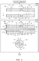
- FIG. 3 is a flowchart showing an example procedure for molding a green insulator.
- FIG. 4 is a flowchart showing the example procedure for molding the green insulator.
- FIG. 5 is a flowchart showing the example procedure for molding the green insulator.
- FIG. 6 is an exploded perspective view of an external mold 200 .
- FIG. 7 is an explanatory view for explaining the length of a rear portion 10 r.
- FIG. 8 is an exploded perspective view of another embodiment of the external mold.
- FIG. 9 is a flowchart showing an example procedure for molding a molded body 10 z in the second embodiment.
- FIG. 10 is a flowchart showing an example procedure for molding the molded body 10 z in the second embodiment.
- FIGS. 11(A)-11(E) are a set of sectional views showing other embodiments of the external mold.
- FIG. 1 is a sectional view of an embodiment of a spark plug.
- FIG. 1 shows a center axis CL (also called an “axial line CL”) of a spark plug 100 .
- the illustrated section is a section which contains the center axis CL.
- a direction parallel to the center axis CL is called the “direction of the axial line CL” or may be called merely the “axial direction” or the “front-back direction.”
- a radial direction of a circle centered on the center axis CL is called merely a “radial direction,” and a circumferential direction of the circle centered on the center axis CL is called merely a “circumferential direction.”
- the forward-end direction Df is called the forward-end direction Df or the forward direction Df
- the upward direction is called the rear-end direction Dfr or the rearward direction Dfr.
- the forward-end direction Df is directed from a metal terminal member 40 toward electrodes 20 and 30 , which will be described later.
- a side in the forward-end direction Df in FIG. 1 is called the forward side of the spark plug 100
- a side in the rear-end direction Dfr is called the rear side of the spark plug 100 .
- the spark plug 100 includes an insulator 10 (also called a “ceramic insulator”), a center electrode 20 , a ground electrode 30 , a metal terminal member 40 , a metallic shell 50 , an electrically conductive first seal member 60 , a resistor 70 , an electrically conductive second seal member 80 , a forward packing 8 , talc 9 , a first rear packing 6 , and a second rear packing 7 .
- an insulator 10 also called a “ceramic insulator”
- the insulator 10 is a substantially cylindrical member having a through hole 12 (hereinafter also called an “axial hole 12 ”) extending therethrough along the center axis C.L.
- the insulator 10 is formed by firing alumina (other electrically insulative materials can also be used).
- the insulator 10 has a leg portion 13 , a first outside-diameter-reducing portion 15 , a forward trunk portion 17 , a third outside-diameter-reducing portion 14 , a collar portion 19 , a second outside-diameter-reducing portion 11 , and a rear trunk portion 18 disposed sequentially in the rearward direction Dfr from the forward side.
- the collar portion 19 (also called the large-diameter portion 19 ) is a portion having the largest outside diameter in the insulator 10 .
- a portion of the insulator 10 other than the large-diameter portion 19 is smaller in outside diameter than the large-diameter portion 19 .
- the outside diameter of the first outside-diameter-reducing portion 15 gradually reduces forward from the rear side.
- the insulator 10 has a first inside-diameter-reducing portion 16 formed in the vicinity of the first outside-diameter-reducing portion 15 (in the forward trunk portion 17 in the example of FIG. 1 ), and the inside diameter of the first inside-diameter-reducing portion 16 gradually reduces forward from the rear side.
- the outside diameter of the second outside-diameter-reducing portion 11 gradually reduces rearward from the forward side.
- the outside diameter of the third outside-diameter-reducing portion 14 gradually reduces forward from the rear side.
- the drawing indicates the axial range in the direction of the axial line CL of a rear portion 10 r of the insulator 10 .
- the rear portion 10 r is a particular portion of the insulator 10 located rearward Dfr of the large-diameter portion 19 .
- the center electrode 20 is inserted into a forward end portion of the axial hole 12 of the insulator 10 .
- the center electrode 20 has a rodlike shaft member 27 extending along the center axis CL and a first tip 29 joined to the forward end of the shaft member 27 .
- the shaft member 27 has a leg portion 25 , a collar portion 24 , and a head portion 23 disposed sequentially in the rearward direction Dfr from the forward side.
- the first tip 29 is joined (for example, by laser welding) to the forward end of the leg portion 25 (i.e., the forward end of the shaft member 27 ). At least a portion of the first tip 29 protrudes from the forward end of the axial hole 12 of the insulator 10 .
- the collar portion 24 is supported by the first inside-diameter-reducing portion 16 of the insulator 10 at the surface on the forward direction Df side.
- the shaft member 27 has an outer layer 21 and a core 22 .
- the outer layer 21 is formed of a material superior in oxidation resistance to the core 22 ; i.e., a material which is less eroded upon exposure to combustion gas in a combustion chamber of an internal combustion engine (e.g., pure nickel or an alloy which contains nickel and chromium).
- the core 22 is formed of a material (e.g., pure copper or a copper alloy) higher in thermal conductivity than the outer layer 21 .
- a rear end portion of the core 22 protrudes from the outer layer 21 and forms a rear end portion of the center electrode 20 .
- the other portion of the core 22 is covered with the outer layer 21 .
- the entire core 22 may be covered with outer layer 21 .
- the first tip 29 is formed of a material superior in durability against discharge to the shaft member 27 (e.g., a noble metal, such as iridium (Ir) or platinum (Pt), tungsten (W), or an alloy which contains at least one selected from these metals).
- a noble metal such as iridium (Ir) or platinum (Pt), tungsten (W), or an alloy which contains at least one selected from these metals).
- the metal terminal member 40 is inserted into a rear portion of the axial hole 12 of the insulator 10 .
- the metal terminal member 40 is formed of an electrically conductive material (e.g., low-carbon steel or a like metal).
- a plug cap 400 is attached to the rearward direction Dfr side of the spark plug 100 .
- the plug cap 400 has, for example, a cap body 410 made of resin and having a cavity 412 , a terminal connection member 420 made of metal and fixed within the cavity 412 , and a ring-like cover 430 made of rubber and fixed to the cap body 410 in such a manner as to surround the cavity 412 .
- An unillustrated plug cord is connected to the terminal connection member 420 .
- the terminal connection member 420 comes into contact with the metal terminal member 40 to thereby electrically connect the plug cord and the metal terminal member 40 .
- the cover 430 comes into close contact with an outer circumferential surface of the insulator 10 (particularly, the rear trunk portion 18 ). As a result, detachment of the plug cap 400 from the spark plug 100 is restrained. Also, entry of water into the cavity 412 from outside is restrained.
- the resistor 70 having a substantially circular columnar shape is disposed within the axial hole 12 of the insulator 10 between the metal terminal member 40 and the center electrode 20 for restraining electrical noise.
- the resistor 70 is formed of, for example, a material which contains an electrically conductive material (e.g., carbon particles), ceramic particles (e.g., ZrO 2 particles), and glass particles (e.g., SiO 2 —B 2 O 3 —Li 2 O—BaO glass particles).
- the electrically conductive first seal member 60 is disposed between the resistor 70 and the center electrode 20
- the electrically conductive second seal member 80 is disposed between the resistor 70 and the metal terminal member 40 .
- the seal members 60 and 80 are formed of a material which contains glass particles similar to those contained in the material of the resistor 70 and metal particles (e.g., Cu particles).
- the center electrode 20 and the metal terminal member 40 are electrically connected through the resistor 70 and the seal members 60 and 80 .
- the metallic shell 50 is a substantially cylindrical member having a through hole 59 extending therethrough along the center axis CL.
- the metallic shell 50 is formed of low-carbon steel (other electrically conductive materials (e.g., a metal material) can also be used).
- the insulator 10 is inserted into the through hole 59 of the metallic shell 50 .
- the metallic shell 50 is fixed to the outer circumference of the insulator 10 .
- the forward end of the insulator 10 (in the present embodiment, a forward end portion of the leg portion 13 ) protrudes from the forward end of the through hole 59 of the metallic shell 50 .
- the rear end of the insulator 10 protrudes from the rear end of the through hole 59 of the metallic shell 50 .
- the metallic shell 50 has a trunk portion 55 , a seat portion 54 , a deformed portion 58 , a tool engagement portion 51 , and a crimp portion 53 disposed sequentially rearward from the forward side.
- the seat portion 54 is a collar-like portion.
- the trunk portion 55 is a substantially cylindrical portion extending from the seat portion 54 in the forward direction Df along the center axis CL.
- the trunk portion 55 has a thread 52 formed on the outer circumferential surface thereof and adapted to threadingly engage the trunk portion 55 with a mounting hole of an internal combustion engine.
- An annular gasket 5 formed by bending a metal plate is fitted between the seat portion 54 and the thread 52 .
- the metallic shell 50 has an inside-diameter-reducing portion 56 disposed forward Df of the deformed portion 58 .
- the inside diameter of the inside-diameter-reducing portion 56 gradually reduces rearward.
- the forward packing 8 is held between the inside-diameter-reducing portion 56 of the metallic shell 50 and the first outside-diameter-reducing portion 15 of the insulator 10 .
- the forward packing 8 is an O-shaped ring made of iron (other materials (e.g., a metal material such as copper) can also be used).
- a tool for tightening the spark plug 100 (e.g., a spark plug wrench) is engaged with the tool engagement portion 51 .
- the tool engagement portion 51 has an external shape resembling a hexagonal column extending along the center axis CL.
- the crimp portion 53 is disposed rearward of the second outside-diameter-reducing portion 11 of the insulator 10 and forms a rear end (i.e., an end on the rearward direction Dfr side) of the metallic shell 50 .
- the crimp portion 53 is bent radially inward.
- the first rear packing 6 , the talc 9 , and the second rear packing 7 are disposed in this order in the forward direction Df between an internal circumferential surface of the metallic shell 50 and an outer circumferential surface of the insulator 10 .
- these rear packings 6 and 7 are C-shaped rings made of iron (other materials can also be used).
- the crimp portion 53 is crimped in such a manner as to be bent inward. Also, the crimp portion 53 is pressed in the forward direction Df. As a result, the deformed portion 58 is deformed, whereby the insulator 10 is pressed forward in the metallic shell 50 through the packings 6 and 7 and the talc 9 . The forward packing 8 is pressed between the first outside-diameter-reducing portion 15 and the inside-diameter-reducing portion 56 to thereby provide a seal between the metallic shell 50 and the insulator 10 . By the above procedure, the metallic shell 50 is fixed to the insulator 10 .
- the ground electrode 30 has a rodlike shaft member 37 and a second tip 39 joined (by resistance welding, for example) to a distal end portion 31 of the shaft member 37 .
- the proximal end of the shaft member 37 is joined to a forward end surface 57 (i.e., a surface 57 on the forward direction Df side) of the metallic shell 50 .
- the shaft member 37 extends in the forward direction Df from the forward end surface 57 of the metallic shell 50 ; then, is bent toward the center axis CL; and reaches the distal end portion 31 .
- the distal end portion 31 is disposed on the forward direction Df side of the center electrode 20 .
- the second tip 39 is joined (by laser welding, for example) to a surface of the distal end portion 31 which faces the center electrode 20 .
- the second tip 39 is formed of a material superior in durability (against discharge) to the shaft member 37 (e.g., a noble metal, such as iridium (Ir) or platinum (Pt), tungsten (W), or an alloy which contains at least one selected from these metals).
- a noble metal such as iridium (Ir) or platinum (Pt), tungsten (W), or an alloy which contains at least one selected from these metals.
- the first tip 29 of the center electrode 20 and the second tip 39 of the ground electrode 30 form a gap g therebetween for spark discharge.
- the ground electrode 30 faces a forward end portion of the center electrode 20 with the gap g intervening therebetween.
- the shaft member 37 of the ground electrode 30 has an outer layer 35 which forms at least a portion of the surface of the shaft member 37 , and a core 36 embedded in the outer layer 35 .
- the outer layer 35 is formed of a material having excellent oxidation resistance (e.g., an alloy which contains nickel and chromium).
- the core 36 is formed of a material (e.g., pure copper) higher in thermal conductivity than the outer layer 35 .
- FIG. 2 is a flowchart showing an example method for manufacturing the spark plug 100 .
- step S 100 the insulator 10 is manufactured.
- step S 103 a green insulator is molded, and in step S 106 , the green insulator is fired. Before firing, the molded insulator may be machined to a predetermined shape (e.g., end portions may be polished). A method for molding in step S 103 will be described later in detail.
- step S 110 other members of the spark plug 100 are prepared. Specifically, the center electrode 20 , the metal terminal member 40 , the metallic shell 50 , and the rodlike ground electrode 30 are manufactured by publicly known methods. Powder materials for the seal members 60 and 80 and a powder material for the resistor 70 are prepared. In steps S 100 and S 110 , the members are prepared independently of one another.
- step S 120 there is manufactured an assembly which has the insulator 10 , the center electrode 20 , the first seal member 60 , the resistor 70 , the second seal member 80 , and the metal terminal member 40 .
- a publicly known method can be employed for manufacturing the assembly.
- the center electrode 20 , a material for the first seal member 60 , a material for the resistor 70 , and a material for the second seal member 80 are inserted in this order into the through hole 12 of the insulator 10 from an opening 12 r on the rear direction Dfr side.
- the metal terminal member 40 is inserted into the through hole 12 from the opening 12 r, whereby an assembly is manufactured.
- step S 130 the rodlike ground electrode 30 is joined to the metallic shell 50 .
- step S 140 the assembly is fixed to the metallic shell 50 .
- the forward packing 8 the assembly manufactured in step S 120 , the second rear packing 7 , the talc 9 , and the first rear packing 6 are disposed in the through hole 59 of the metallic shell 50 .
- the forward packing 8 intervenes between the first outside-diameter-reducing portion 15 of the insulator 10 and the inside-diameter-reducing portion 56 of the metallic shell 50 .
- the crimp portion 53 of the metallic shell 50 is crimped in such a manner as to be bent inward, whereby the metallic shell 50 and the insulator 10 are assembled together.
- step S 150 the rodlike ground electrode 30 is bent to thereby form the gap g.
- the ground electrode 30 is bent such that the distance across the gap g becomes a predetermined distance. Now, the spark plug 100 has been completed.
- FIGS. 3, 4, and 5 are flowcharts showing an example procedure of a step (S 103 in FIG. 2 ) for molding a green insulator.
- FIG. 4 is continued from FIG. 3
- FIG. 5 is continued from FIG. 4 .
- frames indicative of steps confine schematic sections of molds used in the steps.
- the center axis CL and the directions Df and Dfr are illustrated.
- the disposition of the center axis CL and the directions Df and Dfr in relation to the mold is obtained by applying the disposition of the center axis CL and the directions Df and Dfr in relation to the completed insulator 10 to a molded insulator contained in the mold.
- the schematic sections are taken by cutting with a plane which contains the center axis CL.
- a molded green insulator is also called a “molded body.”
- a direction of the mold parallel to the center axis CL is also called the “front-back direction of the mold.”
- step S 200 a plurality of mold pieces 210 , 220 , 231 , and 232 are assembled to form an external mold 200 .
- the external mold 200 molds an outer circumferential surface of a molded body of the insulator 10 .
- FIG. 6 is an exploded perspective view of the external mold 200 .
- the external mold 200 has the forward mold 210 , the intermediate mold 220 disposed rearward Dfr of the forward mold 210 , and a rear mold 230 disposed rearward Dfr of the intermediate mold 220 .
- the forward mold 210 is also called the “forward mold piece 210 ”; the intermediate mold 220 is also called the “intermediate mold piece 220 ”; and the rear mold 230 is also called the “rear mold piece 230 .”
- the rear mold piece 230 is composed of a first mold piece 231 and a second mold piece 232 disposed forward Df of the first mold piece 231 .
- These four mold pieces 231 , 232 , 220 , and 210 are disposed in this order in the forward direction Df.
- the four mold pieces 231 , 232 , 220 , and 210 form inner circumferential surfaces (also called internal surfaces) around the axial line CL.
- These mold pieces 231 , 232 , 220 , and 210 are formed of metal (other materials can also be used).
- An internal surface 10 o of the external mold 200 ( FIG. 3 ) is a molding surface (also called a “molding surface 10 o ”) for molding the outer circumferential surface of a molded body of the insulator 10 .
- the molding surface 10 o is formed by connecting the internal surfaces of the four mold pieces 231 , 232 , 220 , and 210 .
- the reference numerals of portions of the molding surface 10 o of the external mold 200 are those of corresponding portions of the insulator 10 with the suffix “o.”
- An internal surface 19 o of the intermediate mold piece 220 molds the outer circumferential surface of the large-diameter portion 19 .
- the internal surface of the forward mold piece 210 molds the outer circumferential surface of a portion located forward Df of the large-diameter portion 19 .
- the internal surface of the rear mold piece 230 molds the outer circumferential surface of a portion located rearward Dfr of the large-diameter portion 19 .
- the forward mold piece 210 has internal surfaces 14 o, 17 o, 15 o, and 13 o. These internal surfaces 14 o, 17 o, 15 o, and 13 o are continuously disposed in this order in the forward direction Df.
- the internal surface 14 o is connected to the internal surface 19 o of the intermediate mold piece 220 on the forward direction Df side and molds the outer circumferential surface of the third outside-diameter-reducing portion 14 .
- the inside diameter of the internal surface 14 o gradually reduces in the forward direction Df.
- the internal surface 17 o molds the outer circumferential surface of the forward trunk portion 17 ; the internal surface 15 o molds the outer circumferential surface of the first outside-diameter-reducing portion 15 ; and the internal surface 13 o molds the outer circumferential surface of the leg portion 13 .
- the inside diameter of the internal surface 15 o gradually reduces in the forward direction Df.
- the rear mold piece 230 has internal surfaces 18 o and 11 o.
- the internal surfaces 18 o and 11 o of the rear mold piece 230 are divided into the internal surface of the first mold piece 231 and the internal surface of the second mold piece 232 .
- the first mold piece 231 has an internal surface 18 o 1 , which is a portion of the internal surface 18 o located on the rearward direction Dfr side.
- the second mold piece 232 has an internal surface 18 o 2 , which is a portion of the internal surface 18 o located on the forward direction Df side, and the internal surface 11 o connected to the internal surface 18 o 2 on the forward direction Df side.
- the internal surface 18 o 1 of the first mold piece 231 molds the outer circumferential surface of a portion of the rear trunk portion 18 located on the rearward direction Dfr side.
- the internal surface 18 o 2 of the second mold piece 232 is connected to the internal surface 18 o 1 on the forward direction Df side and molds the outer circumferential surface of a portion of the rear trunk portion 18 located on the forward direction Df side.
- the internal surface 11 o of the second mold piece 232 molds the outer circumferential surface of the second outside-diameter-reducing portion 11 .
- the inside diameter of the internal surface 11 o gradually increases in the forward direction Df.
- the internal surface 19 o is connected to the internal surface 11 o on the forward direction Df side.
- the shapes of the above-described internal surfaces of the external mold 200 are identical to external shapes of corresponding portions of a molded body of the insulator 10 .
- step S 200 a plurality of the mold pieces 231 , 232 , 220 , 210 are assembled (connected), whereby the internal surfaces of the mold pieces 231 , 232 , 220 , and 210 are connected to form the molding surface 10 o.
- the shape of the molding surface 10 o is identical to the external shape of a molded body of the insulator 10 .
- a space Si surrounded by the molding surface 10 o corresponds to a molded body of the insulator 10 .
- a rod member 300 is disposed in the space Si.
- the rod member 300 extends along the axial line CL.
- the rod member 300 is formed of, for example, metal (other materials can also be used).
- An external surface 12 i of the rod member 300 is a molding surface (also called a “molding surface 12 i ”) for molding the circumferential wall surface of the through hole 12 of the insulator 10 ( FIG. 1 ).
- the shape of the molding surface 12 i is identical to the shape of the wall surface of an axial hole of the molded body (corresponding to the axial hole 12 of the insulator 10 ).
- the rod member 300 can be said to be a portion of the mold.
- the external surface 12 i of the rod member 300 is divided into three portions 18 i, 16 i, and 13 i.
- the first external surface 18 i molds the inner circumferential surface of a portion of the insulator 10 located rearward Dfr of the first inside-diameter-reducing portion 16 .
- the second external surface 16 i is connected to the first external surface 18 i on the forward direction Df side and molds the inner circumferential surface of the first inside-diameter-reducing portion 16 of the insulator 10 .
- the outside diameter of the second external surface 16 i gradually reduces in the forward direction Df.
- the third external surface 13 i is connected to the second external surface 16 i on the forward direction Df side and molds the inner circumferential surface of a portion of the insulator 10 located forward Df of the first inside-diameter-reducing portion 16 .
- step S 210 the rod member 300 is inserted into the space Si from the rearward direction Dfr side.
- the external mold 200 and the rod member 300 define a space Sx located between the internal surface 10 o of the external mold 200 and the external surface 12 i of the rod member 300 , a ring-like first opening OPf communicating with the space Sx and located on the forward-end direction Df side, and a ring-like second opening OPr communicating with the space Sx and located on the rear-end direction Dfr side.
- a rear end mold 290 for closing the second opening OPr is further disposed on the rearward direction Dfr side of the external mold 200 .
- the shape of the space Sx is identical to the shape of a molded body of the insulator 10 .
- a nozzle 500 of an injection machine is connected to the first opening OPf.
- the nozzle 500 injects a material into the space Sx through the first opening OPf.
- the first opening OPf is used as a gate.
- a molded body 10 z is molded.
- the material contains, for example, alumina and sintering aids.
- a mold 600 for molding the molded body 10 z i.e., the insulator 10 ) has the external mold 200 , the rod member 300 , and the rear end mold 290 .
- the drawing shows the range of a rear molded portion 10 zr of the molded body 10 z in the direction of the axial line CL, and an axial hole 12 z.
- the rear molded portion 10 zr corresponds to the rear portion 10 r of the insulator 10 ( FIG. 1 ).
- the axial hole 12 z is a through hole corresponding to the axial hole 12 of the insulator 10 .
- the internal surfaces 18 o and 11 o of the rear mold piece 230 include an internal surface whose shape is identical to the external shape of the rear molded portion 10 zr.
- the external surface 12 i of that portion of the rod member 300 disposed in the space Si which is located in a space Sp (S 200 ) surrounded by the rear mold 230 includes a portion whose shape is identical to the shape of a portion of the axial hole 12 of the insulator 10 formed in the rear molded portion 10 zr. That is, a space Sr between the internal surfaces 18 o and 11 o of the rear mold piece 230 and the external surface 12 i of the rod member 300 corresponds to the rear molded portion 10 zr.
- the rear end mold 290 and the first mold piece 231 are removed from the molded body 10 z.
- the rear end mold 290 is moved in the rearward direction Dfr in relation to the molded body 10 z to thereby be removed from the molded body 10 z.
- the first mold piece 231 is moved in the rearward direction Dfr in relation to the molded body 10 z to thereby be removed from the molded body 10 z.
- the second mold piece 232 is moved in the rearward direction Dfr in relation to the molded body 10 z to thereby be removed from the molded body 10 z.
- the second mold piece 232 starts to be moved in relation to the molded body 10 z.
- the second mold piece 232 is moved in relation to the molded body 10 z.
- the first mold piece 231 and the second mold piece 232 do not have a portion whose inside diameter increases in the rearward direction Dfr. Therefore, by moving the mold pieces 231 and 232 in the rearward direction Dfr, the mold pieces 231 and 232 can be removed from the molded body 10 z while restraining deformation of the molded body 10 z.
- the forward mold piece 210 is moved in the forward direction Df in relation to the molded body 10 z to thereby remove the forward mold piece 210 from the molded body 10 z.
- the forward mold piece 210 does not have a portion whose inside diameter increases in the forward direction Df. Therefore, by moving the forward mold piece 210 in the forward direction Df, the forward mold piece 210 can be removed from the molded body 10 z while restraining deformation of the molded body 10 z.
- the intermediate mold piece 220 is moved in the forward direction Df in relation to the molded body 10 z to thereby remove the intermediate mold piece 220 from the molded body 10 z.
- the intermediate mold piece 220 may be moved in the rearward direction Dfr in relation to the molded body 10 z.
- the rod member 300 is moved in the rearward direction Dfr in relation to the molded body 10 z to thereby remove the rod member 300 from the molded body 10 z.
- the rod member 300 does not have a portion whose outside diameter reduces in the rearward direction Dfr.
- the rod member 300 can be removed from the molded body 10 z while restraining deformation of the molded body 10 z. Now, all of the mold pieces have been removed from the molded body 10 z.
- the rear mold piece 230 is disassembled into a plurality of the mold pieces 231 and 232 , whereby the molded body 10 z is released from the rear mold piece 230 (S 230 and S 240 in FIG. 4 ).
- the first mold piece 231 forms a portion of the internal surface of the rear mold piece 230 along the entire circumference of the internal surface
- the second mold piece 232 forms a portion of the internal surface of the rear mold piece 230 along the entire circumference of the internal surface located on the forward direction Df side of the first mold piece 231 . Therefore, the first mold piece 231 and the second mold piece 232 can be removed separately from each other.
- the second mold piece 232 is moved in the rearward direction Dfr in relation to the rear molded portion 10 zr.
- force e.g., frictional force
- deformation of the rear molded portion 10 zr can be restrained in releasing the rear molded portion 10 zr from the mold piece.
- the first mold piece 231 forms a portion of the internal surfaces 18 o and 11 o of the rear mold piece 230 located on the rearward direction Dfr side with respect to a direction parallel to the axial line CL.
- the second mold piece 232 forms a portion of the internal surfaces 18 o and 11 o of the rear mold piece 230 on the forward direction Df side with respect to the direction parallel to the axial line CL.
- the mold pieces 231 and 232 form different portions of the internal surfaces 18 o and 11 o of the rear mold piece 230 which differ in axial ranges in the direction parallel to the axial line CL.
- the cover 430 for the plug cap 400 is attached to the rear trunk portion 18 of the insulator 10 .
- the inclination of the outer circumferential surface of the rear trunk portion 18 from the axial line CL (such an inclination that the outside diameter reduces in the rearward direction Dfr) is large, adhesion between the cover 430 and the rear trunk portion 18 may deteriorate. Deterioration in adhesion between the cover 430 and the rear trunk portion 18 causes the formation of a gap between the cover 430 and the rear trunk portion 18 , potentially resulting in generation of discharge from the metal terminal member 40 to the metallic shell 50 through the gap.
- the inclination of the outer circumferential surface of the rear trunk portion 18 from the axial line CL is preferably small.
- the inclinations of the internal surfaces of the mold pieces 231 and 232 are preferably small.
- a first inclination d 1 a/ d 1 b shown in step S 200 of FIG. 3 indicates the inclination of the internal surface 18 o 1 of the first mold piece 231
- a second inclination d 2 a/ d 2 b indicates the inclination of the internal surface 18 o 2 of the second mold piece 232 .
- the inclination d 1 a/ d 1 b (d 2 a/ d 2 b ) indicates the ratio of a positional change d 1 a (d 2 a ) in a direction perpendicular to the axial line CL to a positional change d 1 b (d 2 b ) in a direction parallel to the axial line CL.
- Inclinations d 1 a/ d 1 b and d 2 a/ d 2 b of zero indicate that the internal surfaces 18 o 1 and 18 o 2 are parallel to the axial line CL. Inclinations d 1 a/ d 1 b and d 2 a/ d 2 b greater than zero indicate that the internal surfaces 18 o 1 and 18 o 2 reduce in diameter in the rearward direction Dfr.
- these inclinations d 1 a/ d 1 b and d 2 a/ d 2 b are preferably small.
- the first inclination d 1 a/ d 1 b is 5/1,000 or less.
- the second inclination d 2 a/ d 2 b is 5/1,000 or less.
- an inclination of 5/1,000 or less may be implemented even at a portion of the internal surface 18 o 1 .
- an inclination of 5/1,000 or less may be implemented even at a portion of the internal surface 18 o 2 .
- at least one of the entire internal surface of the first mold piece 231 and the entire internal surface of the second mold piece 232 may have an inclination in excess of 5/1,000.
- the rear mold piece 230 does not have a portion whose inside diameter increases in the rearward direction Dfr, and has only at least one of a portion whose inside diameter remains unchanged in the rearward direction Dfr, and a portion whose inside diameter reduces in the rearward direction Dfr.
- This profile feature allows the mold pieces 231 and 232 to be readily removed from the molded body 10 z while deformation of the rear molded portion 10 zr is restrained, by moving the mold pieces 231 and 232 of the rear mold piece 230 in the rearward direction Dfr.
- FIG. 7 is an explanatory view for explaining the length of the rear portion 10 r.
- the drawing shows a section of the insulator 10 taken by cutting with a plane which contains the axial line CL.
- a position P (called a “forward end position P”) in the drawing indicates the position of an end of the rear portion 10 r on the forward direction Df side.
- the drawing includes at the bottom an enlarged view showing the forward end position P and its periphery.
- the forward end position P is specified as follows.
- the forward end position P is an intersection P between an extension line extending from a straight portion 18 L of the surface of the rear trunk portion 18 which is located closest to the second outside-diameter-reducing portion 11 , and an extension line extending from a straight portion 11 L of the surface of the second outside-diameter-reducing portion 11 which is located most distant from the rear trunk portion 18 .
- a length Lr (called a “rear portion length Lr”) in the drawing is the length of the rear portion 10 r in parallel to the axial line CL; i.e., the distance in parallel to the axial line CL between the forward end position P and an end 10 e of the insulator 10 on the rearward direction Dfr side.
- the rear portion length Lr is 30 mm or more. Even in the case of employment of such a length, as mentioned above, since the rear mold piece 230 is disassembled into the mold pieces 231 and 232 to thereby be removed from the molded body 10 z, deformation of the rear molded portion 10 zr can be restrained in releasing the rear molded portion 10 zr from the rear mold piece 230 .
- the spark plug 100 increases in size. In order to avoid an excessive increase in size of the spark plug 100 , the employment of a short rear portion length Lr is preferred; for example, a rear portion length Lr of 60 mm or less is preferred.
- the rear portion length Lr may be less than 30 mm.
- FIG. 7 also indicates a minimum wall thickness Tm of the rear portion 10 r.
- the inside diameter of the axial hole 12 is such that a portion 12 p including the opening 12 r on the rearward direction Dfr side of the insulator 10 is slightly greater in inside diameter than the other portion of the axial hole 12 .
- the minimum wall thickness Tm is a thickness at this portion 12 p.
- An end portion on the rearward direction side Dfr of the insulator 10 may be chamfered.
- the minimum wall thickness Tm is specified at a portion of the rear portion 10 r remaining after removing the chamfered portion.
- the minimum wall thickness Tm is specified at a portion of the rear portion 10 r remaining after removing a rear end portion 10 re, which ranges from the end 10 e on the rearward direction Dfr side over a distance of 3 mm or less in parallel to the axial line CL.
- the diameter of the insulator 10 is preferably small.
- the minimum wall thickness Tm of the rear portion 10 r also becomes small.
- the minimum wall thickness Tm may be 2.6 mm or less.
- the rear molded portion 10 zr is apt to deform in removing the rear mold piece 230 from the rear molded portion 10 zr.
- the minimum wall thickness Tm is preferably large; for example, a minimum wall thickness Tm of 1.5 mm or more is preferred.
- the minimum wall thickness Tm may be in excess of 2.6 mm.
- An employed dimensional profile may be such that the minimum wall thickness Tm is 2.6 mm or less, and the rear portion length Lr is 30 mm or more. In this case, both a reduction in size of the spark plug 100 and restraint of unintended discharge can be readily implemented. In this case also, since the rear mold piece 230 is disassembled into the mold pieces 231 and 232 to thereby be removed from the molded body 10 z, deformation of the rear molded portion 10 zr can be restrained in releasing the rear molded portion 10 zr from the rear mold piece 230 .
- FIG. 8 is an exploded perspective view of another embodiment of the external mold. Difference from the external mold 200 of FIGS. 3 and 6 is that the rear mold 230 is replaced with a rear mold 240 (called the “rear mold piece 240 ”).
- An external mold 200 b of the second embodiment has the forward mold piece 210 , the intermediate mold piece 220 , and the rear mold piece 240 .
- the forward mold piece 210 and the intermediate mold piece 220 are similar to the forward mold piece 210 and the intermediate mold piece 220 , respectively, of FIGS. 3 and 6 .
- the internal surface of the rear mold piece 240 has a shape identical to that of the internal surface of the rear mold piece 230 of the first embodiment.
- the rear mold piece 240 is composed of a first mold piece 241 and a second mold piece 242 .
- the mold pieces 241 and 242 are obtained by bisecting the rear mold piece 240 with a plane which contains the axial line CL.
- FIGS. 9 and 10 are flowcharts showing an example procedure of a step (S 103 in FIG. 2 ) for molding the molded body 10 z in the second embodiment.
- FIG. 10 is continued from FIG. 9 . Similar to FIGS. 3 to 5 , in the drawings, frames indicative of steps confine schematic sections of molds used in the steps.
- step S 200 b the mold pieces 210 , 220 , 241 , and 242 are assembled to form the external mold 200 b.
- the internal surface 10 o of the assembled external mold 200 b has a shape identical to that of the internal surface of the external mold 200 of the first embodiment.
- step S 210 b the rod member 300 is disposed in the space Si surrounded by the internal surface 10 o. Further, the rear end mold 290 for closing the second opening OPr is disposed on the rearward direction Dfr side of the external mold 200 b.
- step S 210 FIG. 3
- the frame indicative of step S 210 b of FIG. 9 shows, at the bottom, a section taken perpendicularly to the axial line CL. The section is taken across the rear mold piece 240 and the rod member 300 .
- the first mold piece 241 forms a portion of the internal surface of the rear mold piece 240 along a circumferential half (herein, an upper half) of the internal surface
- the second mold piece 242 forms a portion of the internal surface of the rear mold piece 240 along the remaining circumferential half (herein, a lower halt) of the internal surface.
- a nozzle 500 of an injection apparatus is connected to the first opening OPf, and a material is injected into the space Sx.
- the molded body 10 z is molded.
- a mold 600 b for molding the molded body 10 z i.e., the insulator 10
- the rear end mold 290 and the rear mold piece 240 are removed from the molded body 10 z.
- the rear end mold 290 is moved in the rearward direction Dfr in relation to the molded body 10 z to thereby be removed from the molded body 10 z.
- the first mold piece 241 and the second mold piece 242 are moved away from the molded body 10 z perpendicularly or obliquely in relation to the axial line CL to thereby be removed from the molded body 10 z.
- the first mold piece 241 is moved upward, and the second mold piece 242 is moved downward.
- Step S 230 b Processing subsequent to step S 230 b is similar to that subsequent to step S 250 of FIG. 4 . Now, the molded body 10 z has been molded.
- the first mold piece 241 forms a portion of the internal surfaces 18 o and 11 o of the rear mold piece 240 along a circumferential half around the axial line CL.
- the second mold piece 242 forms a portion of the internal surfaces 18 o and 11 o of the rear mold piece 240 along the remaining circumferential half around the axial line CL.
- the mold pieces 241 and 242 form respective portions of the internal surfaces 18 o and 11 o of the rear mold piece 240 which differ in circumferential range.
- the mold pieces 241 and 242 which constitute the rear mold piece 240 can be removed from the molded body 10 z by moving the mold pieces 241 and 242 away from the molded body 10 z perpendicularly or obliquely in relation to the axial line CL.
- the mold pieces can be removed from the molded body 10 z without need to move the mold pieces along the outer surface of the rear molded portion 10 zr while the internal surfaces of the mold pieces are in contact with the outer surface of the rear molded portion 10 zr. Therefore, there can be restrained application of force from a moving mold piece to the rear molded portion 10 zr. As a result, deformation of the rear molded portion 10 zr can be restrained in releasing the rear molded portion 10 zr from the mold piece.
- FIGS. 11(A)-11(E) are a set of sectional views showing other embodiments of the external mold.
- FIGS. 11(A) to 11(C) are sectional views taken by cutting with a plane which contains the axial line CL
- FIGS. 11(D) and 11(E) are sectional views taken perpendicularly to the axial line CL.
- An external mold 200 c of FIG. 11(A) is the external mold 200 of FIG. 3 in which the rear mold piece 230 is replaced with a rear mold piece 230 c.
- the external mold 200 c forms the internal surface 10 o identical to the internal surface 10 o of the external mold 200 .
- the rear mold piece 230 c is composed of three mold pieces 231 c, 232 c, and 233 c.
- the rear mold piece 230 c forms the internal surfaces 18 o and 11 o identical to the internal surfaces 18 o and 11 o of the rear mold piece 230 of FIG. 3 .
- the three mold pieces 231 c, 232 c, and 233 c are disposed in this order in the forward direction Df.
- the first mold piece 231 c forms a portion of the internal surface of the rear mold piece 230 c along the entire circumference of the internal surface; the second mold piece 232 c forms a portion of the internal surface of the rear mold piece 230 c along the entire circumference of the internal surface located on the forward direction Df side of the first mold piece 231 c; and the third mold piece 233 c forms a portion of the internal surface of the rear mold piece 230 c along the entire circumference of the internal surface located on the forward direction Df side of the second mold piece 232 c.
- the rear mold piece 230 c is disassembled into the three mold pieces 231 c, 232 c, and 233 c, whereby the molded body is released from the rear mold piece 230 c. Specifically, the first mold piece 231 c is moved in the rearward direction Dfr; subsequently, the second mold piece 232 c is moved in the rearward direction Dfr; subsequently, the third mold piece 233 c is moved in the rearward direction Dfr. Since the greatest possible area of contact between the rear molded portion 10 zr ( FIG.
- An external mold 200 d of FIG. 11(B) is similar to the external mold 200 of FIG. 3 except that the intermediate mold piece 220 and the rear mold piece 230 are collectively replaced with a rear mold piece 230 d.
- the external mold 200 d forms the same internal surface 10 o as that of the external mold 200 .
- the rear mold piece 230 d is composed of two mold pieces 231 and 232 d.
- the first mold piece 231 is identical to the first mold piece 231 of FIG. 3 .
- the shape of the second mold piece 232 d is the collective shape of the second mold piece 232 and the intermediate mold piece 220 of FIG. 3 .
- the second mold piece 232 d does not have a portion whose inside diameter increases in the rearward direction Dfr. Therefore, after the molded body is molded, by moving the first mold piece 231 in the rearward direction Dfr and then moving the second mold piece 232 d in the rearward direction Dfr, the rear mold piece 230 d can be removed from the molded body. As a result, deformation of the rear molded portion 10 zr ( FIG. 3 ) can be restrained in releasing the rear molded portion 10 zr from the mold piece.
- An external mold 200 e of FIG. 11(C) has a forward mold piece 210 e and a rear mold piece 230 e.
- the rear mold piece 230 e is composed of the first mold piece 231 and a second mold piece 232 e.
- the first mold piece 231 is identical to the first mold piece 231 of FIG. 3 .
- the shape of the second mold piece 232 e is the collective shape of the second mold piece 232 and a portion on the rearward direction Dfr side of the intermediate mold piece 220 of FIG. 3 .
- the shape of the forward mold piece 210 e is identical to the collective shape of the forward mold piece 210 and the remaining portion (a portion on the forward direction Dfr side) of the intermediate mold piece 220 of FIG. 3 .
- the external mold 200 e forms the same internal surface 10 o as that of the external mold 200 of FIG. 3 .
- the second mold piece 232 e does not have a portion whose inside diameter increases in the rearward direction Dfr. Therefore, after the molded body is molded, by moving the first mold piece 231 in the rearward direction Dfr and then moving the second mold piece 232 e in the rearward direction Dfr, the rear mold piece 230 e can be removed from the molded body. As a result, deformation of the rear molded portion 10 zr ( FIG. 3 ) can be restrained in releasing the rear molded portion 10 zr from the mold piece.
- the forward mold piece 210 e does not have a portion whose inside diameter increases in the forward direction Df. Therefore, after the molded body is molded, by moving the forward mold piece 210 e in the forward direction Df, the forward mold piece 210 e can be readily removed from the molded body 10 z.
- a rear mold piece 240 f of FIG. 11(D) can be used in place of the rear mold piece 240 of FIGS. 8 and 9 .
- the rear mold piece 240 f forms the same internal surfaces (not shown) as the internal surfaces 18 o and 11 o of the rear mold piece 240 of FIG. 9 .
- the rear mold piece 240 f differs from the rear mold piece 240 of FIGS. 8 and 9 only in that the rear mold piece 240 f is composed of three circumferentially disposed mold pieces 241 f, 242 f, and 243 f. Each of the three mold pieces 241 f, 242 f, and 243 f forms a portion of the internal surface of the rear mold piece 240 f along one-third of the circumference.
- a rear mold piece 240 g of FIG. 11(E) can be used in place of the rear mold piece 240 of FIGS. 8 and 9 .
- the rear mold piece 240 g forms the same internal surfaces (not shown) as the internal surfaces 18 o and 11 o of the rear mold piece 240 of FIG. 9 .
- the rear mold piece 240 g differs from the rear mold piece 240 of FIGS. 8 and 9 only in that the rear mold piece 240 g is composed of four circumferentially disposed mold pieces 241 g, 242 g, 243 g, and 244 g.
- Each of the four mold pieces 241 g, 242 g, 243 g, and 244 g forms a portion of the internal surface of the rear mold piece 240 g along one-fourth of the circumference.
- the mold pieces which constitute the rear mold pieces 240 f and 240 g may be moved away from the molded body perpendicularly or obliquely in relation to the axial line CL.
- the mold pieces can be removed from the molded body 10 z without need to move the mold pieces along the outer surface of the rear molded portion 10 zr while the internal surfaces of the mold pieces are in contact with the outer surface of the rear molded portion 10 zr ( FIG. 3 ). Therefore, there can be restrained application of force from a moving mold piece to the rear molded portion 10 zr. As a result, deformation of the rear molded portion 10 zr can be restrained in releasing the rear molded portion 10 zr from the mold piece.
- the number of the axial ranges is not limited to 2 ( FIG. 3 ) or 3 ( FIG. 11(A) ), but may be 4 or more.
- various methods in which a plurality of mold pieces are moved in the rearward direction Dfr sequentially from the mold piece on the rearward direction Dfr side can be employed for removing the mold pieces from a molded body.
- the mold piece which has started to move moves entirely rearward Dfr of the end 10 ze ( FIG.
- the next mold piece starts to move.
- the process of moving the mold pieces can be simplified, whereby application of force from a moving mold piece to the rear molded portion 10 zr can be restrained.
- the next mold piece may start to move before the mold piece which has started to move moves entirely rearward Dfr of the end of the molded body 10 z on the rearward direction Dfr side.
- the number of circumferential ranges is not limited to 2 ( FIG. 9 ), 3 ( FIG. 11(D) ), or 4 ( FIG. 11(E) ), but may be 5 or more.
- the mold pieces can be removed from the molded body 10 z by moving the mold pieces perpendicularly or obliquely in relation to the axial line CL rather than moving the mold pieces in parallel to the axial line CL. Therefore, the rear portion 10 r of the insulator 10 may have a portion whose outside diameter increases in the rearward direction Dfr.
- a circumferential range covered by a single mold piece may differ among the mold pieces.
- a circumferential range covered by a single mold piece is semicircumference or less (i.e., the central angle is 180 degrees or less). Employment of this profile feature can restrain the mold pieces from pulling the molded body 10 z in moving the mold pieces perpendicularly or obliquely in relation to the axial line CL.
- a mold piece for molding over at least a partial axial range along the axial line CL may further have a plurality of mold pieces which differ in circumferential range.
- the second mold piece 232 of FIG. 3 may be divided into a plurality of mold pieces which differ in circumferential range. Employment of such a mold structure can further restrain application of force from a moving mold piece to the rear molded portion 10 zr.
- a mold piece (e.g., the forward mold piece 210 ( FIG. 3 ) or 210 e ( FIG. 11(C) ) for molding a portion located forward Df of the large-diameter portion 19 may be divided into a plurality of mold pieces.
- a single mold piece is used to mold the outer circumferential surface of a portion of the insulator 10 to be exposed to combustion gas; i.e., a portion on the forward direction Df side from the first outside-diameter-reducing portion 15 in contact with the forward packing 8 (a portion including the first outside-diameter-reducing portion 15 ).
- a single mold piece can restrain the formation of fine protrusions, such as a parting line, on the outer circumferential surface of the portion on the forward direction Df side from the first outside-diameter-reducing portion 15 , concentration of stress on protrusions can be restrained, or local temperature increase of protrusions can be restrained, which could otherwise result from the formation of protrusions. Therefore, a portion of the insulator 10 to be exposed to combustion gas (i.e., a portion whose temperature is apt to increase) can be improved in heat resistance.
- any other method can be employed.
- a material may be injected into the space Sx from a nozzle connected to the second opening OPr with the first opening OPf closed with another mold piece.
- a material may be injected into the space Sx from a gate provided at a mold piece (e.g., the intermediate mold piece 220 of FIG. 3 ) of the external mold and communicating with the space Sx.
- the rear end mold 290 ( FIG. 3 ) may be a portion of the external mold (e.g., the first mold piece 231 ). Also, the rear end mold 290 may be a portion of the rod member 300 .
- the forward end mold may he a portion of the external mold (e.g., the forward mold piece 210 ). Also, the forward end mold may be a portion of the rod member 300 .
- the rod member 300 may be formed by connecting a plurality of mold pieces.
- the rod member 300 may be composed of a mold piece having the third external surface 13 i, and a mold piece having the external surface extending in the rearward direction Dfr from the second external surface 16 i inclusive.
- removing the rod member 300 composed of a plurality of mold pieces from the molded body 10 z preferably, after a certain mold piece starts to move in relation to the molded body 10 z, another mold piece starts to move in relation to the molded body 10 z.
- various other structures can be employed.
- at least one of the first tip 29 of the center electrode 20 and the second tip 39 of the ground electrode 30 may be eliminated.
- a forward portion of the insulator 10 may be entirely disposed within the through hole 59 of the metallic shell 50 .
- various shapes different from the shape described with reference to FIG. 1 may be employed.
- the shape of the ground electrode 30 various shapes different from the shape described with reference to FIG. 1 may be employed.
- the insulator 10 is described as a substantially cylindrical member having the through hole 12 extending therethrough along the center axis CL; however, the insulator 10 is not limited thereto, but may be a closed-bottomed tubular member having a closed forward end.
Landscapes
- Engineering & Computer Science (AREA)
- Ceramic Engineering (AREA)
- Manufacturing & Machinery (AREA)
- Mechanical Engineering (AREA)
- Chemical & Material Sciences (AREA)
- Spark Plugs (AREA)
Abstract
Description
- 5 . . . gasket
- 6 . . . first rear packing
- 7 . . . second rear packing
- 8 . . . forward packing
- 9 . . . talc
- 10 . . . insulator (ceramic insulator)
- 10 o . . . internal surface (molding surface)
- 10 r . . . rear portion,
- 10 e, 10 ze . . . end
- 10 z . . . molded body
- 10 re . . . rear end portion
- 10 zr . . . rear molded portion
- 11 . . . second outside-diameter-reducing portion
- 11L . . . straight portion
- 11 o . . . internal surface
- 12 . . . through hole (axial hole)
- 12 i . . . external surface (molding surface)
- 12 p . . . portion
- 12 r . . . opening
- 12 z . . . axial hole
- 13 . . . leg portion
- 13 i . . . third external surface
- 13 o . . . internal surface
- 14 . . . third outside-diameter-reducing portion
- 14 o . . . internal surface
- 15 . . . first outside-diameter-reducing portion
- 15 o . . . internal surface
- 16 . . . first inside-diameter-reducing portion
- 16 i . . . second external surface
- 17 . . . forward trunk portion
- 17 o . . . internal surface
- 18 . . . rear trunk portion
- 18L . . . straight portion
- 18 i . . . first external surface1
- 18 o . . . internal surface
- 18
o 1 . . . internal surface - 18
o 2 . . . internal surface - 19 . . . large-diameter portion (collar portion)
- 19 o . . . internal surface
- 20 . . . center electrode
- 21 . . . outer layer
- 22 . . . core
- 23 . . . head portion
- 24 . . . collar portion
- 25 . . . leg portion
- 27 . . . shaft member
- 29 . . . first tip
- 30 . . . ground electrode
- 31 . . . distal end portion
- 35 . . . outer layer
- 36 . . . core
- 37 . . . shaft member
- 39 . . . second tip
- 40 . . . metal terminal member
- 50 . . . metallic shell
- 51 . . . tool engagement portion
- 52 . . . thread
- 53 . . . crimp portion
- 54 . . . seat portion
- 55 . . . trunk portion
- 56 . . . inside-diameter-reducing portion
- 57 . . . forward end surface
- 58 . . . deformed portion
- 59 . . . through hole
- 60 . . . first seal member
- 70 . . . resistor
- 80 . . . second seal member
- 100 . . . spark plug,
- 200, 200 b, 200 c, 200 d, 200 e . . . external mold
- 210, 210 e . . . forward mold (forward mold piece)
- 220 . . . intermediate mold (intermediate mold piece)
- 230, 230 c, 230 d, 230 e . . . rear mold (rear mold piece)
- 231, 231 c . . . first mold piece
- 232, 232 c, 232 d, 232 e . . . second mold piece
- 233 c . . . third mold piece
- 240, 240 f, 240 g . . . rear mold (rear mold piece)
- 241, 242, 241 f to 243 f, 241 g to 244 g . . . mold piece
- 290 . . . rear end mold
- 300 . . . rod member
- 400 . . . plug cap
- 410 . . . cap body
- 412 . . . cavity
- 420 . . . terminal connection member
- 430 . . . cover
- 500 . . . nozzle
- 600, 600 b . . . mold
- g . . . gap
- P . . . forward end position
- CL . . . center axis (axial line)
- Df . . . forward-end direction (forward direction)
- Si, Sr, Sx . . . space
- Tm . . . minimum wall thickness
- Sp . . . space
- Lr . . . rear portion length
- OPf . . . first opening
- OPr . . . second opening
- Dfr . . . rear-end direction (rearward direction)
Claims (5)
Applications Claiming Priority (3)
| Application Number | Priority Date | Filing Date | Title |
|---|---|---|---|
| JP2014-249079 | 2014-12-09 | ||
| JP2014249079 | 2014-12-09 | ||
| PCT/JP2015/004823 WO2016092723A1 (en) | 2014-12-09 | 2015-09-23 | Spark plug insulator production method, insulator, molding die |
Publications (2)
| Publication Number | Publication Date |
|---|---|
| US20170326765A1 US20170326765A1 (en) | 2017-11-16 |
| US10751923B2 true US10751923B2 (en) | 2020-08-25 |
Family
ID=56106964
Family Applications (1)
| Application Number | Title | Priority Date | Filing Date |
|---|---|---|---|
| US15/534,529 Expired - Fee Related US10751923B2 (en) | 2014-12-09 | 2015-09-23 | Spark plug insulator production method, insulator, molding die |
Country Status (5)
| Country | Link |
|---|---|
| US (1) | US10751923B2 (en) |
| EP (1) | EP3232520B1 (en) |
| JP (1) | JP6466311B2 (en) |
| CN (1) | CN107112727B (en) |
| WO (1) | WO2016092723A1 (en) |
Families Citing this family (2)
| Publication number | Priority date | Publication date | Assignee | Title |
|---|---|---|---|---|
| JP6781141B2 (en) * | 2017-12-08 | 2020-11-04 | 日本特殊陶業株式会社 | Spark plug |
| CN112863788B (en) * | 2021-01-14 | 2022-07-22 | 中电国基南方集团有限公司 | Glass insulator manufacturing device and method |
Citations (12)
| Publication number | Priority date | Publication date | Assignee | Title |
|---|---|---|---|---|
| JPS63149705U (en) | 1987-03-25 | 1988-10-03 | ||
| JPH08183062A (en) | 1994-12-28 | 1996-07-16 | Nabco Ltd | Molding method for resin piston |
| WO2002020246A1 (en) | 2000-09-05 | 2002-03-14 | Advanced Plastics Technologies, Ltd. | Multilayer containers and preforms having barrier properties utilizing recycled material |
| US20060042610A1 (en) | 2004-08-31 | 2006-03-02 | Denso Corporation | Spark plug with increased durability |
| JP2006210142A (en) | 2005-01-28 | 2006-08-10 | Ngk Spark Plug Co Ltd | Spark plug and method for manufacturing the same |
| JP2010228342A (en) | 2009-03-27 | 2010-10-14 | Toyo Seikan Kaisha Ltd | Synthetic resin container, preform, method for producing synthetic resin container, and preform mold |
| US20120068390A1 (en) * | 2008-04-10 | 2012-03-22 | Walker Jr William John | Ceramic Spark Plug Insulator And Method Of Making |
| DE102010042155A1 (en) | 2010-10-07 | 2012-04-12 | Robert Bosch Gmbh | Ceramic injection molding tool for manufacturing insulator of spark plug of engine, has core element with end contacting with central region of sprue device, and another core element movably arranged in cavity in longitudinal direction |
| JP2013131375A (en) | 2011-12-21 | 2013-07-04 | Ngk Spark Plug Co Ltd | Ignition plug |
| DE102012200046A1 (en) * | 2012-01-03 | 2013-07-04 | Robert Bosch Gmbh | Method and tool for producing a hollow cylindrical ceramic component |
| WO2013102514A1 (en) | 2012-01-03 | 2013-07-11 | Robert Bosch Gmbh | Injection molding tool and method for producing a ceramic component |
| EP2741382A1 (en) | 2011-08-04 | 2014-06-11 | NGK Spark Plug Co., Ltd. | Ignition plug |
Family Cites Families (2)
| Publication number | Priority date | Publication date | Assignee | Title |
|---|---|---|---|---|
| US3077649A (en) * | 1963-02-19 | Process of envelopment | ||
| JP2009259775A (en) * | 2008-03-19 | 2009-11-05 | Ngk Spark Plug Co Ltd | Insulator for spark plug and method of manufacturing spark plug |
-
2015
- 2015-09-23 WO PCT/JP2015/004823 patent/WO2016092723A1/en not_active Ceased
- 2015-09-23 EP EP15867522.3A patent/EP3232520B1/en active Active
- 2015-09-23 CN CN201580067275.XA patent/CN107112727B/en not_active Expired - Fee Related
- 2015-09-23 US US15/534,529 patent/US10751923B2/en not_active Expired - Fee Related
- 2015-12-09 JP JP2015240127A patent/JP6466311B2/en not_active Expired - Fee Related
Patent Citations (13)
| Publication number | Priority date | Publication date | Assignee | Title |
|---|---|---|---|---|
| JPS63149705U (en) | 1987-03-25 | 1988-10-03 | ||
| JPH08183062A (en) | 1994-12-28 | 1996-07-16 | Nabco Ltd | Molding method for resin piston |
| WO2002020246A1 (en) | 2000-09-05 | 2002-03-14 | Advanced Plastics Technologies, Ltd. | Multilayer containers and preforms having barrier properties utilizing recycled material |
| US20060042610A1 (en) | 2004-08-31 | 2006-03-02 | Denso Corporation | Spark plug with increased durability |
| JP2006210142A (en) | 2005-01-28 | 2006-08-10 | Ngk Spark Plug Co Ltd | Spark plug and method for manufacturing the same |
| US20120068390A1 (en) * | 2008-04-10 | 2012-03-22 | Walker Jr William John | Ceramic Spark Plug Insulator And Method Of Making |
| JP2010228342A (en) | 2009-03-27 | 2010-10-14 | Toyo Seikan Kaisha Ltd | Synthetic resin container, preform, method for producing synthetic resin container, and preform mold |
| DE102010042155A1 (en) | 2010-10-07 | 2012-04-12 | Robert Bosch Gmbh | Ceramic injection molding tool for manufacturing insulator of spark plug of engine, has core element with end contacting with central region of sprue device, and another core element movably arranged in cavity in longitudinal direction |
| EP2741382A1 (en) | 2011-08-04 | 2014-06-11 | NGK Spark Plug Co., Ltd. | Ignition plug |
| JP2013131375A (en) | 2011-12-21 | 2013-07-04 | Ngk Spark Plug Co Ltd | Ignition plug |
| US20140346945A1 (en) * | 2011-12-21 | 2014-11-27 | Ngk Spark Plug Co., Ltd. | Spark plug |
| DE102012200046A1 (en) * | 2012-01-03 | 2013-07-04 | Robert Bosch Gmbh | Method and tool for producing a hollow cylindrical ceramic component |
| WO2013102514A1 (en) | 2012-01-03 | 2013-07-11 | Robert Bosch Gmbh | Injection molding tool and method for producing a ceramic component |
Non-Patent Citations (3)
| Title |
|---|
| Extended European Search Report issued in corresponding European Patent Application No. 15867522.3 dated Jun. 19, 2018. |
| International Search Report from corresponding International Patent Application No. PCT/JP2015/004823, dated Dec. 22, 2015. |
| Office Action issued in corresponding Japanese Patent Application No. 2015-240127 dated Aug. 16, 2018 (with English-language machine translation). |
Also Published As
| Publication number | Publication date |
|---|---|
| JP2016111024A (en) | 2016-06-20 |
| CN107112727B (en) | 2019-01-04 |
| EP3232520A1 (en) | 2017-10-18 |
| CN107112727A (en) | 2017-08-29 |
| EP3232520A4 (en) | 2018-07-18 |
| US20170326765A1 (en) | 2017-11-16 |
| JP6466311B2 (en) | 2019-02-06 |
| WO2016092723A1 (en) | 2016-06-16 |
| EP3232520B1 (en) | 2020-09-09 |
Similar Documents
| Publication | Publication Date | Title |
|---|---|---|
| KR101062528B1 (en) | Spark Plugs for Internal Combustion Engines | |
| JP5406261B2 (en) | Spark plug and manufacturing method thereof | |
| KR20100054762A (en) | Spark plug | |
| KR20120003891A (en) | Spark ignition device having bridging ground electrode and construction method thereof | |
| US20170047712A1 (en) | Spark plug | |
| US10751923B2 (en) | Spark plug insulator production method, insulator, molding die | |
| KR20110128872A (en) | Spark Plugs for Internal Combustion Engines | |
| CN106716753B (en) | Insulator and spark plug | |
| JP4804524B2 (en) | Spark plug for internal combustion engine and method for manufacturing the same | |
| JP5972337B2 (en) | Method for manufacturing an insulator for a spark plug | |
| JP6270703B2 (en) | Insulator manufacturing method for spark plug and mold | |
| JP6335770B2 (en) | Method for manufacturing an insulator for a spark plug | |
| JP6347735B2 (en) | Method for manufacturing an insulator for a spark plug | |
| US20100201245A1 (en) | Spark plug having a plastic upper insulator and method of construction | |
| JP5535097B2 (en) | Manufacturing method of spark plug metal shell and manufacturing method of spark plug | |
| JP7250456B2 (en) | Insulator for spark plug, spark plug, method for manufacturing insulator | |
| JP2020202111A (en) | Manufacturing method of tubular metal fitting | |
| JP6675340B2 (en) | Bar member | |
| JP6077397B2 (en) | Manufacturing method of spark plug | |
| JP5783950B2 (en) | Manufacturing method of spark plug | |
| JP4693126B2 (en) | Spark plug and method of manufacturing spark plug | |
| JP2018152310A (en) | Spark plug |
Legal Events
| Date | Code | Title | Description |
|---|---|---|---|
| AS | Assignment |
Owner name: NGK SPARK PLUG CO., LTD., JAPAN Free format text: ASSIGNMENT OF ASSIGNORS INTEREST;ASSIGNORS:KURONO, HIROKAZU;UEGAKI, HIRONORI;HONDA, TOSHITAKA;AND OTHERS;REEL/FRAME:042657/0494 Effective date: 20170531 |
|
| STPP | Information on status: patent application and granting procedure in general |
Free format text: DOCKETED NEW CASE - READY FOR EXAMINATION |
|
| STPP | Information on status: patent application and granting procedure in general |
Free format text: NON FINAL ACTION MAILED |
|
| STPP | Information on status: patent application and granting procedure in general |
Free format text: NOTICE OF ALLOWANCE MAILED -- APPLICATION RECEIVED IN OFFICE OF PUBLICATIONS |
|
| STPP | Information on status: patent application and granting procedure in general |
Free format text: PUBLICATIONS -- ISSUE FEE PAYMENT VERIFIED |
|
| STCF | Information on status: patent grant |
Free format text: PATENTED CASE |
|
| FEPP | Fee payment procedure |
Free format text: MAINTENANCE FEE REMINDER MAILED (ORIGINAL EVENT CODE: REM.); ENTITY STATUS OF PATENT OWNER: LARGE ENTITY |
|
| LAPS | Lapse for failure to pay maintenance fees |
Free format text: PATENT EXPIRED FOR FAILURE TO PAY MAINTENANCE FEES (ORIGINAL EVENT CODE: EXP.); ENTITY STATUS OF PATENT OWNER: LARGE ENTITY |
|
| STCH | Information on status: patent discontinuation |
Free format text: PATENT EXPIRED DUE TO NONPAYMENT OF MAINTENANCE FEES UNDER 37 CFR 1.362 |
|
| FP | Lapsed due to failure to pay maintenance fee |
Effective date: 20240825 |