US10751638B2 - High efficiency distillation head and methods of use - Google Patents
High efficiency distillation head and methods of use Download PDFInfo
- Publication number
- US10751638B2 US10751638B2 US16/188,271 US201816188271A US10751638B2 US 10751638 B2 US10751638 B2 US 10751638B2 US 201816188271 A US201816188271 A US 201816188271A US 10751638 B2 US10751638 B2 US 10751638B2
- Authority
- US
- United States
- Prior art keywords
- condenser
- column
- distillation head
- distillation
- insulation chamber
- Prior art date
- Legal status (The legal status is an assumption and is not a legal conclusion. Google has not performed a legal analysis and makes no representation as to the accuracy of the status listed.)
- Active
Links
Images


Classifications
-
- B—PERFORMING OPERATIONS; TRANSPORTING
- B01—PHYSICAL OR CHEMICAL PROCESSES OR APPARATUS IN GENERAL
- B01D—SEPARATION
- B01D3/00—Distillation or related exchange processes in which liquids are contacted with gaseous media, e.g. stripping
- B01D3/14—Fractional distillation or use of a fractionation or rectification column
- B01D3/32—Other features of fractionating columns ; Constructional details of fractionating columns not provided for in groups B01D3/16 - B01D3/30
-
- B—PERFORMING OPERATIONS; TRANSPORTING
- B01—PHYSICAL OR CHEMICAL PROCESSES OR APPARATUS IN GENERAL
- B01D—SEPARATION
- B01D3/00—Distillation or related exchange processes in which liquids are contacted with gaseous media, e.g. stripping
- B01D3/02—Distillation or related exchange processes in which liquids are contacted with gaseous media, e.g. stripping in boilers or stills
-
- B—PERFORMING OPERATIONS; TRANSPORTING
- B01—PHYSICAL OR CHEMICAL PROCESSES OR APPARATUS IN GENERAL
- B01D—SEPARATION
- B01D5/00—Condensation of vapours; Recovering volatile solvents by condensation
- B01D5/0003—Condensation of vapours; Recovering volatile solvents by condensation by using heat-exchange surfaces for indirect contact between gases or vapours and the cooling medium
-
- B—PERFORMING OPERATIONS; TRANSPORTING
- B01—PHYSICAL OR CHEMICAL PROCESSES OR APPARATUS IN GENERAL
- B01D—SEPARATION
- B01D5/00—Condensation of vapours; Recovering volatile solvents by condensation
- B01D5/0057—Condensation of vapours; Recovering volatile solvents by condensation in combination with other processes
- B01D5/006—Condensation of vapours; Recovering volatile solvents by condensation in combination with other processes with evaporation or distillation
-
- B—PERFORMING OPERATIONS; TRANSPORTING
- B01—PHYSICAL OR CHEMICAL PROCESSES OR APPARATUS IN GENERAL
- B01D—SEPARATION
- B01D5/00—Condensation of vapours; Recovering volatile solvents by condensation
- B01D5/0078—Condensation of vapours; Recovering volatile solvents by condensation characterised by auxiliary systems or arrangements
- B01D5/0087—Recirculating of the cooling medium
Definitions
- the distillation head may be used for efficient fractional distillation of high boiling point compounds, and includes a lower insulated chamber (i.e., a jacket or a vacuum jacket) surrounding or wrapped around a fractionating column (also called a path, inner tube, fractionating column, or fractionating tube) and an upper insulated chamber (i.e., a jacket or vacuum jacket) surrounding a condenser.
- a lower insulated chamber i.e., a jacket or a vacuum jacket
- a fractionating column also called a path, inner tube, fractionating column, or fractionating tube
- an upper insulated chamber i.e., a jacket or vacuum jacket
- the lower insulated chamber may also feature a vacuum chamber having silvering (mirroring) inside of the vacuum chamber to increase thermal and infrared heat retention in the fractionating column within the lower insulated chamber, while leaving the upper insulated chamber un-silvered (not mirrored) to allow for a temperature differential between the condenser in the upper chamber and the fractionating column in the lower chamber for improved (more efficient) condensation of fractionated vapors.
- An exit path having a cross sectional area that is greater than or substantially equal to the cross section of the fractionating column, is located vertically within the distillation head at or below the top of the fractionating column.
- Distillation systems specifically fractional distillation systems, separate mixtures into their component parts, or fractions, by heating the mixtures to a temperature that causes one or more fractions to vaporize.
- the heated vapors ascend through a fractionating column, some of which condense and revaporize along a temperature gradient.
- the small exit hole slows throughput and provides a small condensation surface area for collecting the distillate.
- the current invention provides a high efficiency distillation head and methods of use.
- the distillation head may be used for efficient fractional distillation of high boiling point compounds, and includes a lower insulated chamber surrounding a fractionating column and an upper insulated chamber surrounding a condenser.
- An exit path having a cross sectional area that is equal to or greater than the cross sectional area of the fractionating column is located on the distillation head at or below the top of the fractionating column.
- the lower insulated chamber can also feature a vacuum chamber having silvering (mirroring) inside of the vacuum chamber (i.e., vacuum jacket) to increase thermal and infrared heat retention, while leaving the upper insulated chamber un-silvered (not mirrored), which allows for a greater temperature differential and greater condensation efficiency of fractionated vapors.
- a distillation head may be used in conjunction with a vacuum system and heated boiling flask (with product inside) to fractionate and separate high boiling point compounds.
- the device can be used, for example, to separate cannabinoids, from other constituents found in cannabis oils or constituents from other herbs.
- the fractionating column is engineered to promote separation while keeping the fractionating column short enough to keep the energy required below a certain threshold and maintaining the compound in its vapor phase.
- the threshold is 175° C. In one embodiment, the threshold is 180° C. In another embodiment, the threshold is 190° C. In one embodiment, the threshold is 200° C. In another embodiment, the threshold is between about 175° C. and about 210° C.
- the distillation head can maintain a temperature differential between the lower vacuum chamber (fractionating) and the upper vacuum chamber (condensing) without the use of coolants, heaters, or chillers.
- anything exiting the fractionating column has the ability to condense—unlike in previous designs where purified vapors had to exit a restriction area or small hole/opening and enter a secondary condenser.
- the improvement in efficiency due to a larger exit hole (less hold up or restriction) and larger condensation surface area, is a significant improvement over previously produced distillation heads/columns.
- FIG. 1 is a right side elevational view of a distillation head according to selected embodiments of the current disclosure.
- FIG. 2 is a left side elevational view of a distillation head according to selected embodiments of the current disclosure.
- FIG. 3 is a front elevational view of a distillation head according to selected embodiments of the current disclosure.
- FIG. 4 is a rear elevational view of a distillation head according to selected embodiments of the current disclosure.
- FIG. 5 is top elevational view of a distillation head according to selected embodiments of the current disclosure.
- FIG. 6 is a bottom elevational view of a distillation head according to selected embodiments of the current disclosure.
- FIG. 7 is a right side cutaway view of a distillation head according to selected embodiments of the current disclosure.
- FIG. 8 is side view of another embodiment of a distillation head, showing the shortened upper condenser, a shortened fractionating column, and silvering on the lower insulated chamber.
- FIG. 9 is a close up of the embodiment of a distillation head from FIG. 8 , showing detail of the column passing through the floor of the condenser.
- FIG. 10 is a top close up view of the interior of the embodiment of a distillation head from FIG. 8 , showing detail of the restriction in the column.
- FIG. 11 is a side cutaway view of another embodiment of a distillation head, showing a larger diameter condenser and fractionating column.
- FIG. 12 is a side cutaway view of another embodiment of a distillation head, showing a larger diameter condenser and a wider exit port.
- FIG. 13 is a right side elevational view of a distillation head according to selected embodiments of the current disclosure.
- FIG. 14 is a left side elevational view of a distillation head according to selected embodiments of the current disclosure.
- FIG. 15 is a front elevational view of a distillation head according to selected embodiments of the current disclosure.
- FIG. 16 is a rear elevational view of a distillation head according to selected embodiments of the current disclosure.
- FIG. 17 is a top elevational view of a distillation head cutaway from just above the fractionating column, according to selected embodiments of the current disclosure.
- FIG. 18 is a top elevational view of a distillation head cutaway from about halfway up the lower vacuum jacket, according to selected embodiments of the current disclosure.
- FIG. 19 is a right side cutaway view of a distillation head according to selected embodiments of the current disclosure.
- FIG. 20 is a front cutaway view of a distillation head according to selected embodiments of the current disclosure.
- FIG. 21 is a rear cutaway view of a distillation head according to selected embodiments of the current disclosure.
- FIG. 22 is a top cutaway view of a distillation head according to selected embodiments of the current disclosure.
- FIG. 23 is a top cutaway view of a distillation head according to selected embodiments of the current disclosure.
- FIG. 24 is a side cutaway view of another embodiment of a distillation head, showing a larger diameter condenser and an open bottom design to fit a flanged flask, with the fractionating column extending below the bottom of the distillation head.
- FIG. 25 is a side cutaway view of the intersection of a bottom of a distillation head of FIG. 24 , attached to a round-bottom flanged flask, with the fractionating column extending below the bottom of the distillation head into the round-bottom flask.
- FIG. 26 is a right side elevational view of a distillation head according to selected embodiments of the current disclosure.
- FIG. 27 is a left side elevational view of a distillation head according to selected embodiments of the current disclosure.
- FIG. 28 is a front elevational view of a distillation head according to selected embodiments of the current disclosure.
- FIG. 29 is a rear elevational view of a distillation head according to selected embodiments of the current disclosure.
- FIG. 30 is a top elevational view of a distillation head according to selected embodiments of the current disclosure.
- FIG. 31 is a bottom elevational view of a distillation head according to selected embodiments of the current disclosure.
- FIG. 32 is a right side cutaway view of a distillation head according to selected embodiments of the current disclosure.
- FIG. 33 is a front cutaway view of a distillation head according to selected embodiments of the current disclosure.
- FIG. 34 is a rear cutaway view of a distillation head according to selected embodiments of the current disclosure.
- FIG. 35 is a bottom cutaway view of a distillation head according to selected embodiments of the current disclosure.
- FIG. 36 is a top cutaway view of a distillation head according to selected embodiments of the current disclosure.
- FIG. 37 is a right side cutaway view of a distillation head a distillation head according to selected embodiments of the current disclosure, showing a larger diameter condenser and an open bottom design to fit a flanged flask.
- FIG. 38 is a top close up view of the embodiment of a distillation head from FIG. 37 , showing detail of Vigreux indents in the column.
- FIG. 39 is a right side elevational view of a distillation head according to selected embodiments of the current disclosure.
- FIG. 40 is a left side elevational view of a distillation head according to selected embodiments of the current disclosure.
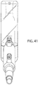
- FIG. 41 is a front elevational view of a distillation head according to selected embodiments of the current disclosure.
- FIG. 42 is a rear elevational view of a distillation head according to selected embodiments of the current disclosure.
- FIG. 43 is a top elevational view of a distillation head according to selected embodiments of the current disclosure.
- FIG. 44 is a bottom elevational view of a distillation head according to selected embodiments of the current disclosure.
- FIG. 45 is a right side cutaway view of a distillation head according to selected embodiments of the current disclosure.
- FIG. 46 is a front cutaway view of a distillation head according to selected embodiments of the current disclosure.
- FIG. 47 is a rear cutaway view of a distillation head according to selected embodiments of the current disclosure.
- FIG. 48 is a bottom cutaway view of a distillation head according to selected embodiments of the current disclosure.
- FIG. 49 is a top cutaway view of a distillation head according to selected embodiments of the current disclosure.
- the distillation head is made up of two main parts: the lower insulated chamber surrounding the fractionating column and the upper insulated chamber surrounding the condenser.
- the device has heat insulation surrounding the fractionating column, which may be filled with an array of packing materials or structured packings to increase surface area for fractionation.
- the packing materials are glass beads or any other objects suitable for use in a distillation head that increase the surface area.
- the vapors Once the vapors reach the top of the lower insulated chamber, they quickly begin to cool as they exit the fractionating column, which fractionating column has an opening at least as wide as the diameter or cross-section of the exit. In some embodiments, the diameter or cross-section of the exit is wider than the diameter of the fractionating column. In some embodiments, as discussed below, the diameter or cross section of the exit is less than the diameter of the fractionating column.
- the fractionating column has a similar or smaller cross sectional area to the vapor outlet (exit)
- the low-hold up design allows for maximum vapor throughput and condensation on the outer walls of the upper insulated chamber.
- the larger surface area of the inner “dome” of the condenser i.e., the upper jacket which is vacuum insulated
- condensed vapors now liquids, flow down towards the sloped bottom of the condenser towards the exit.
- the exit port has the same inner diameter or cross-sectional area as the fractionating column which allows for maximum vacuum flow without restricting the overall flow rate (or to maintain flow rate when there is material inserted in the fractionating column that reduces the flow rate in the fractionating column).
- Other embodiments provide for an exit port that has a larger diameter or cross-sectional area than the fractionating column.
- Some embodiments have an exit port with a smaller diameter or cross sectional area than the exit port to change flow rates.
- the fractionating column is relatively short and, in some embodiments, does not extend into the condenser. In other embodiments, it extends into the condenser but not so much that it disrupts the condenser's efficiency. Utilizing silvering inside of the walls of the lower insulated chamber (for infrared heat retention) greatly improves the efficiency of this design.
- the lower insulated chamber is a vacuum chamber and the silvering is applied while it is unsealed (open at bottom) before it is sealed.
- the silvering is a Silver Nitrate spray coating (usually applied leaving a viewing strip for the fractionating column).
- the silvering can be any reflective material that reflects infrared radiation, whether its actual color is silver, gold, bronze, rose gold, or any other color.
- the lower insulated chamber i.e., vacuum jacket
- the silvering of the lower insulated chamber reflects and traps infrared radiation, or long wave electromagnetic radiation which would otherwise escape through the glass.
- the visible thermal improvements from adding silvering are easily viewable via thermal imaging cameras (FLIR cameras) that detect long wave infrared; when measuring the surface temperatures of the portions of the device with silvering, they appear significantly cooler at high temperatures.
- the silvering on the lower insulated chamber coupled with an un-silvered upper insulated chamber creates an increased temperature differential from the hot lower vacuum chamber to the cool upper insulated chamber thereby causing rapid condensation and increases the maximum throughputs of main fractions (the primary constituent being extracted).
- the flow rates for a 24/40 condenser are between about 100 to 200 g/hr and for a 24/40 condenser.
- the flow rates for a 34/45 distillation head are generally between about 250-500 g/hr.
- the throughput rate of the currently disclosed fractionating column and distillation head is 30% to 300% greater than traditional distillation heads. In one embodiment, the currently disclosed distillation head is larger than existing traditional distillation heads and has a throughput above 1000 g/hour. In one embodiment, the temperature differential between the lower insulation chamber 22 and the upper insulation chamber 31 of the device is between about 5 and 30° C.
- FIGS. 1-6 show various views of a distillation head 10 according to selected embodiments of the current disclosure.
- FIG. 7 is a right side cutaway of the same embodiment shown in FIGS. 1 to 6 of a distillation head 10 according to selected embodiments of the current disclosure.
- the distillation head 10 includes a fractionating column 21 surrounded by a lower insulation chamber (i.e., a lower jacket) 22 .
- the inner wall 20 of the lower insulation chamber 22 is silvered to help retain infrared heat.
- the lower insulation chamber 22 surrounds, encircles, wraps around or fits around fractionating column 21 to further retain heat within the fractionating column 21 .
- Certain embodiments of the current disclosure have a lower vacuum insulating chamber 22 , wherein the chamber is devoid or substantially devoid of matter.
- Alternative embodiments provide for a chamber that is filled with insulating material or insulated, for example using vacuum jackets, double vacuum jackets, inert gas, physical insulation, heating oil jacket, liquid jackets, fiberglass, electric heater sleeve, or any other form of insulation.
- the fractionating column 21 has an inner diameter 23 that, in the embodiment shown in this figure, is substantially constant along its vertical length. Nonetheless, projections, protrusions, packing, or other elements may extend from the inner surface of the fractionating column or reside within the fractionating column 21 to increase surface area for fractionation.
- the distillation head 10 has an optional upper joint 37 . In some embodiments, the distillation head 10 has an optional side joint 36 .
- Vapors are supplied to the fractionating column 21 by a contained source, for example, a heated boiling flask 12 , though other sources of vapors are contemplated by the current disclosure, including those that provide a continuous feed of vapors. Vapors exit the column 21 to enter into the condenser 32 .
- the condenser 32 has an upper jacket 31 .
- the upper jacket is non-silvered to increase infrared heat transfer out of the condenser to help maintain cooler temperatures inside the condenser 32 .
- an upper insulation chamber 31 surrounds, encircles, wraps around or fits around the condenser 32 .
- Certain embodiments of the current disclosure have an upper vacuum insulating chamber 31 , wherein the chamber is devoid or substantially devoid of matter.
- Alternative embodiments provide for an upper insulating chamber 31 that is filled with insulating material or insulated, for example, using vacuum jackets, double vacuum jackets, inert gas, physical insulation, heating oil jackets, liquid jackets, fiberglass, or any other form of insulation.
- the condenser has no upper jacket surrounding it, but only a single glass wall, while the lower end of the fractionating column has a lower, silvered jacket, which can further differentiate the temperature within the fractionating column compared to the uninsulated condenser.
- the condenser has no upper jacket surrounding it and the condenser has no lower jacket, but the outer walls of the fractionating column are silvered, which can further differentiate the temperature within the silvered fractionating column compared to the uninsulated, unsilvered condenser.
- the condenser has an upper jacket surrounding it, while the lower end of the fractionating column has no lower jacket, but only a single glass, silvered wall, which can differentiate the temperature within the silvered fractionating column compared to the insulated condenser.
- the fractionating column 21 extends upwards and into the condenser 32 through a floor 34 of the condenser 32 .
- the condenser 32 has an inner diameter 35 that is greater than the inner diameter 23 of the fractionating column 21 .
- the condenser 32 can have a cross sectional area that is greater than the cross sectional area of the fractionating column 21 .
- the floor 34 of the condenser 32 slopes downwards towards an exit or distillate port 15 allowing for the exit of distillate out of the chamber of the condenser 32 .
- the distillate port 15 has a diameter 33 .
- the diameter 33 of the distillate port 15 is equal to or substantially equal to the diameter 23 of the fractionating column 21 .
- the diameter 33 of the distillate port 15 is greater than the diameter 23 of the fractionating column 21 .
- the openings of the distillate port 15 and the fractionating column 21 may be defined by a cross sectional area, in which case the cross sectional area of the distillate port 15 is equal to or substantially equal to the cross sectional area 23 of the fractionating column 21 .
- the cross sectional area 33 of the distillate port 15 is greater than the cross sectional area 23 of the fractionating column 21 and in other embodiments, the cross sectional area 33 of the distillate port 15 is the same as or smaller than the cross sectional area 23 of the fractionating column 21 .
- the distillate port 15 is located at the lowest point of the sloped floor 34 so that condensate flows by gravity to the distillate port 15 down the sloped floor 34 . Moreover, in this embodiment, the distillate port 15 is located below the exit or top of the fractionating column 21 .
- a secondary condenser ( 171 in FIGS. 26 and 45 ) provides additional surface area, temperature change, and pressure change to condense additional liquid from the heated vapor.
- the secondary condenser 171 is also an insulated chamber with a vacuum jacket, double vacuum jacket, inert gas, physical insulation, heating oil jacket, liquid jacket, fiberglass, electric heater sleeve, or any other form of insulation. In this way, the secondary condenser 171 can be hotter or colder than the primary condenser 32 , creating a secondary reaction to encourage even greater condensation rates.
- the secondary condenser 171 is wrapped in an insulated sleeve (not shown) that further comprises its own electric heating element (i.e., resistance heater), which electric heating element heats the secondary condenser 171 while the insulated sleeve retains the heat inside the secondary condenser 171 .
- the secondary condenser 171 has a housing or an outer surface and the insulated sleeve wraps around the entire housing or outer surface except for its entry and exit ports and pulloffs. This insulated sleeve retains heat along the entire length of the secondary condenser. In some embodiments, less than the entire length of the secondary condenser 171 is covered.
- an electric resistance heater is located in the sleeve because it is relatively inexpensive to operate and maintain compared to oil and water jackets.
- a liquid jacket with inlet/outlet ports for the secondary condenser one embodiment can have a simple glass tube with about an 1 ⁇ 8 inch trough to fit a thermocouple (bent) in between the glass and the hot mantle jacket. The heat can be maintained and monitored by a temperature controller.
- the sleeve is wrapped around a secondary condenser 171 also having a vacuum jacket or other jacket.
- the sleeve is wrapped around a glass tube. In embodiments with multiple jackets, the jackets can be used together to improve the efficiency of the design.
- an insulated sleeve is wrapped around a secondary condenser having a single glass wall so that the electric heater is in close proximity with the secondary condenser chamber to improve control over the temperature inside the secondary condenser chamber.
- the secondary chamber is surrounded by a vacuum jacket which has a silver lining or is silvered similar to the primary condenser also of the present disclosure described above.
- the insulated sleeve is filled with fiberglass or some other insulating material so that it retains heat from the electric mantle.
- the sleeve is about 11 inches long and about 5 inches in diameter. In other embodiments, the sleeve is between about 8 inches long and 15 inches long.
- the sleeve's diameter is between about 3 inches and 7 inches.
- the sleeves can be braided from nylon, polypropylene, polyester, Nomex®, Kevlar®, Spectra®.
- the sleeve can be stuffed, layered or filled with fiberglass, polyethylene foam insulation or any other material that will retain heat inside the secondary condenser.
- the sleeve has an insulated flap on at least one side that can be opened for viewing the reaction inside the secondary condenser. The insulated flap can be held in the closed position using Velcro or other fasteners so that the flap's insulation is held against the secondary condenser when not opened for viewing.
- one end of the sleeve can be flat so that it can sit close to the outer wall of the primary distillation head.
- the other end can be slightly elongated on either the top or the bottom so that it can cover slightly more or less on the top than the bottom on that end of the sleeve.
- the sleeve can taper or form a curve from the shorter side to the longer side.
- the insulation and the sleeve's cover can be woven.
- the left side of the sleeve can look the same as the right side of the sleeve.
- the ends can look the same from an elevational view.
- both side cutaway views of the sleeve can look the same.
- the insulated sleeve is removable, and fastens to itself around a secondary condenser 171 with Velcro tabs or other fasteners.
- the insulated sleeve can be spread out flat forming a rough rectangular shape, having silver or other colored outer covering on one side and a white or colored insulation on the other side.
- Both the inside and the outside can be woven fiberglass.
- the outside is another material so that it does not irritate a person's skin when handling the sleeve.
- one end of the flattened insulated sleeve can have an elongated section that tapers out from both sides (discussed above to provide additional coverage over a knuckle or joint on one side but not the other of a condenser or glass tube).
- the elongated section extends 11 ⁇ 2 inches longer than the rest of the end.
- the insulation can be between about half inch to 3 inches thick, and in one embodiment the insulated sleeve fits around a 11 ⁇ 8 inch diameter tube. In another embodiment, the insulated sleeve fits around a tube that is between about half inch and 21 ⁇ 2 inches in diameter.
- the insulated sleeve 172 is about 121 ⁇ 2 inches long at its shortest point and 14 inches long at its longest point.
- the heating mantle is a standard 115V, 150 W mantle.
- the method allows distillation at greater rates, in part, because of the drop in pressure caused as the gas leaves the fractionating column 21 and enter the greater volume of space in the condenser 21 .
- the present disclosure comprises a method of distilling a compound comprising the steps of: supplying a vapor from a contained source to a distillation head, where the distillation head comprises: (i) a column with a surrounding insulation chamber, the column having an inner diameter; (ii) a condenser with a surrounding insulation chamber, the condenser having an inner diameter and a floor; and (iii) a distillation port, the distillation port having an inner diameter; (iv) wherein the column extends through the floor of the condenser, the floor of the condenser slopes downward towards the distillation port, the inner diameter of the distillation port is substantially equal to or greater than the inner diameter of the column, and the inner diameter of the condenser is greater than the inner diameter of the column; condensing the vapor to a liquid in the condenser; and collecting liquid from the distillation port.
- the contained source can be a boiling flask, a flask or vessel with an oil jacket or electric mantels, a flask or vessel heated by steam, or any other heated vessel.
- the insulation chamber around the column can be a vacuum chamber.
- the insulation chamber around the condenser can also be a vacuum chamber.
- the distillation head can comprise a silver lining on the insulation chamber around the fractionating column, wherein the silver lining reflects infrared radiation, preventing it from escaping the insulation chamber around the column.
- the silvering increases the efficiency and allows distillation at much lower temperatures than previous devices, in some embodiments, resulting in efficiency increases of 10-35% over existing distillation heads.
- the vapor can be supplied to the distillation head through the column.
- the method can further comprise the step of maintaining a temperature differential of between about 5° and 30° Celsius between the condenser and the column.
- the contained source can be a boiling flask attached to the distillation head.
- the method comprises the additional step of passing the liquid (and remaining vapor) through a secondary condenser 171 where the liquid and gas are reheated using an electric mantle surrounded by an insulated sleeve described above.
- This additional, optional step creates a secondary reaction in which the products of the first distillation head are reheated and catalyzes additional fractionation and distillation.
- one or two inlet ports 36 , 37 may pierce through the upper vacuum jacket to provide the ability for packing insertion into fractionating column 21 , which can, optionally, have Vigreux indents 25 (i.e., packing retainer indents or indents) to support packing at bottom of column 21 , increase the surface area, and increase the turbulence inside the fractionating column 21 .
- the inlet ports may also be used for temperature/pressure sensing via a thermocouple or thermometer immersed into the column to obtain vapor temperature measurements of compounds exiting column 21 .
- These inlet ports 36 , 37 are not required for operation, but do allow for additional data collection and/or modularity of the optional packing material.
- the distillation head 10 is a cylinder that is approximately 262 mm long from a top end to a bottom end and has an outer diameter of 64 mm.
- the diameter of the interior of the condenser 32 is 19 mm.
- the inner diameter of the column 21 is 18.4 mm.
- the inner diameter of the distillation port 15 is 18.4 mm.
- the fractionating column 21 extends about 30 mm above the floor 34 of the condenser 32 and about 74 mm below the floor 34 of the condenser 32 , where it connects to a joint 26 that can add about 55 mm to the length of the fractionating column 21 .
- the floor 34 is angled at a 75° angle from the vertical fractionating column 21 (i.e., 15° downward from horizontal).
- the distillation port 15 continues out of the condenser 32 from the floor 34 at approximately a 62° angle from the vertical.
- the distillation port 15 extends about 85 mm (including the joint) from the exterior of the condenser 32 .
- the optional inlet port 36 is positioned at a 55° angle from the vertical fractionating column 21 and extends about 55 mm, including the joint, from the exterior of the condenser 32 .
- the interior walls of the fractionating column 21 are straight as the column 21 passes through the floor 34 .
- the fractionating column 21 has a restriction area 25 in the bottom half of the column 21 that is formed by four indents positioned around the interior of the column, each at about 90° apart from the next.
- two of the indents are on one vertical plane and two of the indents are on another vertical plane, separated, in one embodiment, by approximately 5 mm.
- the restriction area is about 15 mm above the bottom of the lower insulation chamber 22 .
- the restriction area is used to support additional packing material (not shown) when inserted in the column 21 .
- the condenser 32 is about 136 mm long at its center, extending from the floor 34 to the top of the distillation head 10 .
- the distillation head 10 is about 207 mm from the top of the exterior of the upper insulation chamber 31 to the bottom of the exterior of the lower of the lower insulation chamber 22 .
- a joint 26 at the bottom of the column 21 extends about 55 mm from the end of the lower insulation chamber 22 .
- the silver lining 24 coats or covers the interior walls of the lower insulation chamber 22 located below the floor 34 .
- the distillation head is a cylinder that is approximately 300 mm long from a top end to a bottom end and has an outer diameter of 85 mm.
- the diameter of the interior of the condenser 32 is 80 mm.
- the interior diameter of the column 21 is 30 mm.
- the interior diameter of the distillation port 15 is 18.4 mm.
- the fractionating column 21 extends about 30 mm above the floor 34 of the condenser 32 and about 90 mm below the floor 34 of the condenser 32 .
- the fractionating column 21 extends an additional approximately 65 mm through a joint 26 at the bottom of the distillation head 10 .
- the floor 34 is angled at about an 82° angle from the vertical fractionating column 21 (i.e., 8 degrees downward from the horizontal).
- the distillation port 15 continues out of the condenser 32 from the floor 34 at a 65° angle from the vertical. In one embodiment, the distillation port 15 extends about 85 mm from the exterior of the condenser 32 .
- the inlet port 36 is positioned at a 55° angle from the vertical fractionating column 21 and extends about 55 mm from the exterior of the condenser 32 , including the joint.
- the fractionating column 21 extends an additional approximately 65 mm through a joint 26 at the bottom end of the distillation head 10 . In one embodiment, as shown in FIG.
- the interior walls of the fractionating column 21 are straight as the column 21 passes through the floor 34 .
- the fractionating column 21 has a restriction area 25 in the bottom half of the column 21 that is formed by four indents positioned around the interior of the column, each at about 90° apart from the next.
- the two of the indents are on one vertical plane and two of the indents are on another vertical plane, each plane separated, in one embodiment, by approximately 5 mm.
- the restriction area is about 15 mm above the bottom of the lower insulation chamber 22 .
- the condenser is about 145 mm long, extending from the floor 34 to the top of the distillation head 10 .
- the distillation head 10 is about 235 mm from the top of the exterior of the upper insulation chamber 31 to the bottom of the exterior of the lower of the lower insulation chamber 22 .
- a joint 26 at the bottom of the column 21 extends about 65 mm from the end of the lower insulation chamber 22 .
- the silver lining 24 covers the interior of the lower insulation chamber 22 starting below the floor 34 .
- the distillation head is a cylinder that is approximately 310 mm long from a top end to a bottom end and has an outer diameter of 85 mm.
- the diameter of the interior of the condenser 32 is 80 mm.
- the interior diameter of the column 21 is 40 mm.
- the diameter of the distillation port 15 is 30 mm.
- the fractionating column 21 extends about 30 mm above the floor 34 of the condenser 32 and about 90 mm below the floor 34 of the condenser 32 .
- the floor 34 is angled at approximately an 82° angle from the vertical fractionating column 21 (approximately 8° angle downward from the horizontal).
- the distillation port 15 continues out of the condenser 32 from the floor 34 at a 65° angle from the vertical. In one embodiment, the distillation port 15 extends about 85 mm from the exterior of the condenser 32 . In one embodiment, the optional inlet port 36 is positioned at a 55° angle from the vertical fractionating column 21 and extends about 55 mm from the exterior of the condenser 32 . In one embodiment, the interior walls of the fractionating column 21 are straight as the column 21 passes through the floor 34 . In one embodiment, the fractionating column 21 has a restriction area 25 in the bottom half of the fractionating column 21 that is formed by four indents positioned around the interior of the column, each at about 90° apart from the next.
- the two of the indents are on one vertical plane and two of the indents are on another vertical plane, separated, in one embodiment, by approximately 5 mm.
- the restriction area is about 15 mm above the bottom of the lower insulation chamber 22 .
- the restriction area 25 is used to support additional packing material (not shown) when inserted in the column 21 .
- the condenser is about 140 mm long, including the joint, extending from the floor 34 to the top of the distillation head 10 .
- the distillation head 10 is about 235 mm from the top of the exterior of the upper insulation chamber 31 to the bottom of the exterior of the lower of the lower insulation chamber 22 .
- a joint 26 at the bottom of the fractionating column 21 extends about 75 mm from the bottom of the lower insulation chamber 22 .
- the silver lining 24 covers the interior of the lower insulation chamber 22 starting below the floor 34 .
- FIGS. 13 to 23 and 37 to 38 show another embodiment of the distillation head, which is a cylinder ( FIG. 37 provides numbering) that is 345 mm long from a top end to a bottom end and has an outer diameter of 130 mm.
- the diameter of the interior of the condenser 32 is 86 mm.
- the interior diameter of the column 21 is 56-60 mm.
- the diameter of the distillation port 15 is 30 mm.
- the fractionating column 21 extends about 30 mm above the floor 34 of the condenser 32 and about 165 mm below the floor 34 of the condenser 32 .
- the floor 34 is angled at approximately an 82° angle from the vertical fractionating column 21 (i.e., approximately 8° downward from the horizontal).
- the distillation port 15 continues out of the condenser 32 from the floor 34 at approximately a 65° angle from the vertical. In one embodiment, the distillation port 15 extends about 85 mm from the exterior of the condenser 32 .
- the inlet port 36 is positioned at a 55° angle from the vertical fractionating column 21 and extends about 75 mm from the exterior of the condenser 32 .
- the interior walls of the fractionating column 21 are straight as the fractionating column 21 passes through the floor 34 .
- the fractionating column 21 has indents 25 in the bottom half of the column 21 positioned around the interior of the column, each at about 90° apart from the next. In one embodiment, two or more of the indents are on one vertical plane and two or more of the indents are on another vertical plane. In some embodiments, the fractionating column can have two, three, four, or more indents on each vertical plane. In some embodiments, the fractionating column can have one, two, three, or more vertical planes of indents. In some embodiments, each plane of indents is rotated so that the indents do not align vertically from one plane to another. In one embodiment, the indents of one plane bisect the spaces between the indents of another plane.
- FIG. 38 shows indents as seen looking downward through the fractionating column 21 .
- the restriction area 25 is about 30 mm below the bottom of the lower insulation chamber 22 .
- the restriction area 25 can support additional packing material in the column 21 .
- the condenser is about 175 mm long, extending from the floor 34 to the top of the distillation head 10 .
- a reactor lid clamp 27 at the bottom of the column 21 extends about 70 mm from the end of the lower insulation chamber 22 .
- the distillation head 10 is about 245 mm from the top of the exterior of the upper insulation chamber 31 to the bottom of the exterior of the lower of the lower insulation chamber 22 .
- the silver lining 24 covers the interior of the lower insulation chamber 22 starting below the floor 34 .
- FIG. 13 shows an embodiment of the current disclosure from a right side elevational view with a reactor lid clamp rather than a joint at the bottom, a slivered vacuum jacket surrounding the fractionating column, with a portion of the fractionation column extending above the mirrored vacuum jacket inside the condenser.
- This embodiment has an exit port and two inlet ports, one at the top and one off the top left side.
- FIG. 14 shows the opposite side of the device from FIG. 13 , with all of the same features from the opposite view.
- FIG. 15 shows a front elevational view of the embodiment of the distillation head from the previous figures showing the exit port 15 obscuring part of the top of the distillation port.
- FIG. 16 a back elevational view of the same embodiment, showing, in particular, the inlet port extending upward at an angle from the back of the device.
- the silvered area is taller on the back view of the device because the floor of the condenser chamber also forms the top of the lower vacuum chamber and slopes downward from the back of the device to the front where the exit port is located.
- FIG. 17 shows a top elevational view in which the exit port is shown on the right side and an inlet port is shown on the left side. The view shows into the top inlet port through the fractionating column below.
- FIG. 18 shows a bottom elevational view in which the inlet port is on the left side and the exit port is on the right side of the figure. This view shows into the circular bottom of the distillation head.
- the eight vigreux indents of this embodiment are shown inside the fractionating column and appear larger than FIG. 17 only because they are closer to the view.
- FIG. 19 shows a right side cutaway view of the device showing the orientations of FIGS. 20 to 23 . This view shows that the vigreux indents can be on different vertical planes inside the fractionating column.
- FIG. 19 shows a right side cutaway view of the device showing the orientations of FIGS. 20 to 23 . This view shows that the vigreux indents can be on different vertical planes inside the fractionating column.
- FIG. 20 shows a front cutaway view of the device with an exit port cutaway and showing the inlet port on the back through the glass extending up from the back wall.
- This view shows the upper and lower bounds of the lower vacuum jacket surrounding the fractionating column.
- the lighter shaded horizontal partitions shown in the fractionating column are not actually in the fractionating column, but are actually the top and bottom portions of the lower vacuum jacket outside the fractionating column, but viewable through the glass walls of the fractionating column; they do not obstruct the fractionating column.
- FIG. 21 shows a back cutaway view of the device with the inlet port on the back of the device removed and showing just the top of the exit port, partially obscured by the silvered vacuum jacket around the fractionating column.
- FIGS. 22 and 23 show top cutaway view of one embodiment, FIG. 22 being cut away from just above the fractionating column and FIG. 23 being cut away from about halfway up the lower vacuum jacket.
- the exit port is shown on the left of FIG. 22 , but is cut way on FIG. 23 .
- FIG. 37 is another right side cutaway view described in greater detail previously.
- FIG. 38 shows, in one embodiment, a top view of a single ring of indents in a fractionating column, having four indents on the same vertical plane, each indent positioned 90 degrees from the next indent forming a ring.
- one, two, three or more independent rings of indents are positioned on different vertical planes inside the fractionating column.
- FIG. 37 shows two rings of indents 25 , each ring formed by four different indents 25 .
- a distillation head 10 has features similar to the embodiment shown in FIGS. 13 to 23 and 37 to 38 except that the fractionating column 21 is longer so that it can extend down into a flask when the head is positioned on a flanged flask.
- the indents 25 can be moved lower in the fractionating column 21 (shown) or they can remain higher in the fractionating column (not shown).
- FIG. 25 shows one embodiment of the distillation head 10 attached to a round-bottom flask 42 .
- the flanges at the bottom of the distillation head fit the flanges of the flask 41 , and an o-ring or gasket 40 seals the connection between the distillation head 10 and the flask 42 .
- the indents 25 at the bottom of the fractionating column 21 extend downward from the distillation head 10 into the flask 42 .
- the gasket 40 connects a continuous pocket or area 27 around the fractionating column 21 with the flask 42 .
- This pocket or area 27 becomes a continuation of the heated flask 42 , having similar a similar temperature profile as the flask 42 and allows the heat from the flask 42 to heat the fractionating column 21 from multiple sides.
- the bottom of the lower jacket 22 can be lower so that the area 27 is decreased. In another embodiment, the bottom of the lower jacket 22 can be higher so that the area 27 is increased.
- the flask 42 can be any flask or vessel with a mouth or opening that will seal to the bottom of the distillation head 10 .
- FIG. 26 shows a right side elevational view of another embodiment with a distillation head 10 and a secondary condenser 171 .
- a distillation port 35 connects the distillation head 10 with the secondary condenser 171 .
- the floor 34 of the condenser slopes downward toward the distillation port and forms the ceiling of the lower vacuum jacket.
- the wall 30 of the condenser is shown which also forms the wall of the upper vacuum jacket in this embodiment.
- FIG. 27 shows the left side elevational view of the same embodiment as FIG. 26 showing the opposite side of all the same features.
- FIG. 28 shows a front side elevational view of the same embodiment as FIG. 26 showing the same features from the front view.
- the secondary condenser is shown protruding out from the front of the device.
- FIG. 29 shows a rear elevational view of the embodiment from FIG. 26 showing the silvered lower vacuum jacket 22 and the fractionating column 21 extending up through the ceiling of the lower vacuum jacket.
- the inlet port 36 on the back of the device is also shown.
- FIG. 30 shows a top elevational view of the device showing the orientations of FIGS. 32 to 34 .
- the secondary condenser is extending to the right and an inlet port to the left in this view. This view shows into the top inlet port through the fractionating column below.
- FIG. 31 shows a bottom elevational view of the same embodiment.
- FIG. 32 shows a side cutaway view of one embodiment, in particular showing a side cutaway view of the secondary condenser 171 with the vacuum jacket surrounding it.
- FIG. 33 shows a front cutaway view of the same embodiment as FIGS. 26-32 .
- FIG. 34 shows a back cutaway view of the same embodiment as FIGS. 26-33 .
- FIG. 35 shows a top cutaway view, cut from the top of the condenser with the inlet port extending from the left side. Four vigreux indents can be seen inside the fractionating column of this embodiment. Of course, the number of indents can vary.
- FIG. 36 shows a top cutaway view, cut at the lower half of the lower vacuum chamber.
- FIGS. 37 and 38 were discussed previously.
- FIGS. 39 to 40 show an embodiment of the distillation head 10 that shares the features of the embodiment in FIGS. 26 to 36 , but omits the inlet port from the back side of the condenser and only has a single inlet port 37 on the top of the device 10 .
- the wall 30 of the condenser is unbroken and the upper vacuum jacket does not have an inlet port bridging it to the back.
- the distillation port 35 still bridges the upper jacket to allow distillate to exit from the floor 34 of the condenser.
- the fractionating column still extends up through the floor 34 of the condenser, and the floor 34 of the condenser still forms the ceiling of the lower jacket.
- FIGS. 40 to 49 are, respectively, left side elevational, front elevational, rear elevational, top elevational, bottom elevational, side cutaway, front cutaway, back cutaway, top cutaway and top cutaway views.
- the distillation head and process described herein may be utilized for the distillation of cannabinoids. This distillation head and process may also be used for other high boiling point compounds.
- the devices, apparatuses, and methods disclosed herein may have particular applicability to fractionate and separate high boiling point compounds, such as cannabinoids, from other constituents found in cannabis oils or other constituents from other herbs. Nonetheless, the devices, apparatuses, and methods disclosed herein may equally apply to the distillation of other compounds.
- high boiling point compounds may be distilled under deep vacuum pressure, for example, those below 1 Torr.
- distillation using the device may occur at pressures between 0 and 1500 mTorr.
- the heated temperature may range from ambient to 230° C.
- distillation head made from borosilicate glass, stainless steel, or a combination thereof, though other materials may be used without departing from the scope of the current disclosure.
Abstract
Description
| Output Range of | Output Range of | ||
| Traditional | Disclosed | ||
| Size Distillation Head | Distillation | Distillation Head | |
| 24/40 Distillation Head | 100-200 g/hour | 250-500 g/ |
|
| 34/45 Distillation Head | 250-500 g/hour | 350-1000 g/hour | |
Claims (23)
Priority Applications (6)
| Application Number | Priority Date | Filing Date | Title |
|---|---|---|---|
| US16/188,271 US10751638B2 (en) | 2017-03-03 | 2018-11-12 | High efficiency distillation head and methods of use |
| US29/677,827 USD896920S1 (en) | 2017-08-24 | 2019-01-24 | High efficiency distillation head |
| US29/677,829 USD896922S1 (en) | 2017-08-24 | 2019-01-24 | Vacuum chamber and fractionating column for high efficiency distillation head |
| US29/677,828 USD896921S1 (en) | 2017-08-24 | 2019-01-24 | High efficiency distillation head |
| US29/678,304 USD909606S1 (en) | 2018-11-12 | 2019-01-28 | Cold trap insert |
| US29/678,299 USD984581S1 (en) | 2018-11-12 | 2019-01-28 | Cold trap insert |
Applications Claiming Priority (10)
| Application Number | Priority Date | Filing Date | Title |
|---|---|---|---|
| US29/595,937 USD852928S1 (en) | 2017-03-03 | 2017-03-03 | Short path distillation head |
| US29/595,939 USD877856S1 (en) | 2017-03-03 | 2017-03-03 | Short path distillation head |
| US29/614,928 USD828904S1 (en) | 2017-08-24 | 2017-08-24 | High efficiency distillation head |
| US29/614,926 USD862640S1 (en) | 2017-08-24 | 2017-08-24 | Distillation head |
| US201762580032P | 2017-11-01 | 2017-11-01 | |
| US29/634,400 USD855754S1 (en) | 2018-01-22 | 2018-01-22 | Short path distillation head |
| US16/103,321 US10406451B2 (en) | 2017-08-24 | 2018-08-14 | High efficiency distillation head and methods of use |
| US201862760020P | 2018-11-12 | 2018-11-12 | |
| US201862759987P | 2018-11-12 | 2018-11-12 | |
| US16/188,271 US10751638B2 (en) | 2017-03-03 | 2018-11-12 | High efficiency distillation head and methods of use |
Related Parent Applications (3)
| Application Number | Title | Priority Date | Filing Date |
|---|---|---|---|
| US29/614,926 Continuation-In-Part USD862640S1 (en) | 2017-03-03 | 2017-08-24 | Distillation head |
| US29/634,400 Continuation-In-Part USD855754S1 (en) | 2017-03-03 | 2018-01-22 | Short path distillation head |
| US16/103,321 Continuation-In-Part US10406451B2 (en) | 2017-03-03 | 2018-08-14 | High efficiency distillation head and methods of use |
Related Child Applications (6)
| Application Number | Title | Priority Date | Filing Date |
|---|---|---|---|
| US16/103,321 Continuation-In-Part US10406451B2 (en) | 2017-03-03 | 2018-08-14 | High efficiency distillation head and methods of use |
| US29/677,827 Continuation-In-Part USD896920S1 (en) | 2017-08-24 | 2019-01-24 | High efficiency distillation head |
| US29/677,829 Continuation-In-Part USD896922S1 (en) | 2017-08-24 | 2019-01-24 | Vacuum chamber and fractionating column for high efficiency distillation head |
| US29/677,828 Continuation-In-Part USD896921S1 (en) | 2017-08-24 | 2019-01-24 | High efficiency distillation head |
| US29/678,304 Continuation-In-Part USD909606S1 (en) | 2018-11-12 | 2019-01-28 | Cold trap insert |
| US29/678,299 Continuation-In-Part USD984581S1 (en) | 2018-11-12 | 2019-01-28 | Cold trap insert |
Publications (2)
| Publication Number | Publication Date |
|---|---|
| US20190076752A1 US20190076752A1 (en) | 2019-03-14 |
| US10751638B2 true US10751638B2 (en) | 2020-08-25 |
Family
ID=65630227
Family Applications (1)
| Application Number | Title | Priority Date | Filing Date |
|---|---|---|---|
| US16/188,271 Active US10751638B2 (en) | 2017-03-03 | 2018-11-12 | High efficiency distillation head and methods of use |
Country Status (1)
| Country | Link |
|---|---|
| US (1) | US10751638B2 (en) |
Cited By (4)
| Publication number | Priority date | Publication date | Assignee | Title |
|---|---|---|---|---|
| US10874955B2 (en) * | 2020-07-13 | 2020-12-29 | Elliot Kremerman | Short distillation head with integrated cooling jacket |
| US10967292B1 (en) | 2021-01-07 | 2021-04-06 | Elliot Kremerman | Distillation tube and fraction collector with concave interior wall |
| US10987607B2 (en) * | 2020-07-13 | 2021-04-27 | Elliot Kremerman | Short distillation head with integrated cooling spiral |
| US11612830B2 (en) * | 2020-05-22 | 2023-03-28 | Agustus Berman Shelander | Short path distillation head |
Families Citing this family (8)
| Publication number | Priority date | Publication date | Assignee | Title |
|---|---|---|---|---|
| USD896921S1 (en) * | 2017-08-24 | 2020-09-22 | Lab Society Llc | High efficiency distillation head |
| USD896920S1 (en) * | 2017-08-24 | 2020-09-22 | Lab Society Llc | High efficiency distillation head |
| USD896922S1 (en) * | 2017-08-24 | 2020-09-22 | Lab Society Llc | Vacuum chamber and fractionating column for high efficiency distillation head |
| USD909606S1 (en) * | 2018-11-12 | 2021-02-02 | Lab Society Llc | Cold trap insert |
| USD875881S1 (en) * | 2019-07-01 | 2020-02-18 | Elliot Kremerman | Short distillation head |
| USD875880S1 (en) * | 2019-07-01 | 2020-02-18 | Elliot Kremerman | Short distillation head comprising a vertical tube filled with a key |
| USD949285S1 (en) * | 2020-11-23 | 2022-04-19 | Elliot Kremerman | Distillation unit with magnetic spinner |
| USD919040S1 (en) | 2021-01-07 | 2021-05-11 | Elliot Kremerman | Distillation tube with fraction collector |
Citations (53)
| Publication number | Priority date | Publication date | Assignee | Title |
|---|---|---|---|---|
| US2427142A (en) * | 1943-03-02 | 1947-09-09 | Corning Glass Works | Still head condenser |
| US2468872A (en) * | 1945-01-01 | 1949-05-03 | Pure Oil Co | Distilling head |
| US3340157A (en) * | 1963-11-22 | 1967-09-05 | Electro Glass Lab Inc | Distilland treating and condensing apparatus |
| US3393133A (en) * | 1965-06-16 | 1968-07-16 | Artisan Ind | Short path, molecular fractional distillation apparatus and method therefor |
| US3395083A (en) * | 1966-04-08 | 1968-07-30 | Gilmont Roger | Laboratory distilling apparatus |
| US3607662A (en) * | 1968-08-08 | 1971-09-21 | Sinclair Oil Corp | Fractional distillation apparatus having vapor flow control means for alternate condensers |
| US3907683A (en) * | 1973-10-29 | 1975-09-23 | Gilmont Instr Inc | Multitubular constant head reflux condenser |
| US4471836A (en) * | 1982-01-15 | 1984-09-18 | Arthur C. Knox, Jr. | Vent condenser |
| US5164049A (en) * | 1986-10-06 | 1992-11-17 | Athens Corporation | Method for making ultrapure sulfuric acid |
| US5354428A (en) * | 1986-10-06 | 1994-10-11 | Athens Corp. | Apparatus for the continuous on-site chemical reprocessing of ultrapure liquids |
| US5885313A (en) * | 1996-09-12 | 1999-03-23 | Shionogi & Co., Ltd. | Temperature-gradient type multistage condenser |
| US6419796B1 (en) * | 2000-10-26 | 2002-07-16 | President Of Nagoya University | Solvent distillation apparatus |
| US6551464B1 (en) | 2000-02-17 | 2003-04-22 | Howard Kimel | Distillation/reflux equipment |
| US6596129B1 (en) * | 1999-11-08 | 2003-07-22 | Nippon Shokubai Co., Ltd. | Distillation process for easily polymerizable substance-containing solution |
| CN2702775Y (en) | 2004-05-28 | 2005-06-01 | 王修同 | Petroleum pressure reducing distillation standard apparatus |
| US7267746B1 (en) | 2001-02-26 | 2007-09-11 | Uop Llc | Dividing wall distillation column control apparatus |
| CN201079707Y (en) | 2007-07-27 | 2008-07-02 | 南京师范大学 | Constant temperature extraction vacuum distillation device |
| EP2294931A1 (en) | 2009-09-02 | 2011-03-16 | Drom Fragrances GmbH & Co. KG | Improved process and improved apparatus for yielding plant ingredients |
| CN202823431U (en) | 2012-08-24 | 2013-03-27 | 洛阳新巨能高热技术有限公司 | Pressure reduction distilling head |
| US8414744B2 (en) | 2007-09-11 | 2013-04-09 | Basf Se | Continuous process for preparing menthol in pure or enriched form |
| CN103623880A (en) | 2012-08-24 | 2014-03-12 | 洛阳新巨能高热技术有限公司 | Distilling head for vacuum distillation |
| US20150136158A1 (en) * | 2013-11-15 | 2015-05-21 | Jj 206, Llc | Systems and methods for a vaporization device and product usage control and documentation |
| US9040730B2 (en) | 2011-02-11 | 2015-05-26 | E I Du Pont De Nemours And Company | Purification of triglyceride oil from microbial sources using short path distillation |
| US9138657B1 (en) | 2011-07-28 | 2015-09-22 | Elemental Scientific, Inc. | Fractional-volatilization separator |
| US9340475B2 (en) | 2014-07-02 | 2016-05-17 | Cv Sciences, Inc. | Process for generating hemp oil with a high cannabidiol (CBD) content |
| CN105606423A (en) | 2016-02-26 | 2016-05-25 | 河南中烟工业有限责任公司 | Extracting device and extracting method for volatile and semivolatile components in sample |
| CN205287678U (en) | 2015-12-29 | 2016-06-08 | 天津市长芦化工新材料有限公司 | Vacuum silvering rectifier unit |
| CN205598689U (en) | 2016-04-26 | 2016-09-28 | 南通宝凯化工有限公司 | Rectification device |
| USD775310S1 (en) | 2016-04-11 | 2016-12-27 | Elliot Kremerman | Bent distillation head |
| US20170003264A1 (en) * | 2014-01-24 | 2017-01-05 | The University Of Wyoming Research Corporation D/B/A Western Research Institute | Volatile Hydrocarbon Separation and Analysis Apparatus and Methods |
| USD776238S1 (en) | 2016-04-11 | 2017-01-10 | Elliot Kremerman | Straight path distillation head |
| US9649349B1 (en) | 2017-01-19 | 2017-05-16 | Metamorphic Alchemy & Distillations, Inc. | System and method for producing a terpene-enhanced cannibinoid concentrate |
| USD788316S1 (en) | 2016-05-13 | 2017-05-30 | Elliot Kremerman | Laboratory filter |
| USD790033S1 (en) | 2016-12-30 | 2017-06-20 | Elliot Kremerman | Distillation key |
| US9682331B2 (en) * | 2016-12-30 | 2017-06-20 | Elliot Kremerman | Distillation key and method of use |
| USD802085S1 (en) | 2016-04-11 | 2017-11-07 | Elliot Kremerman | Straight path distillation head |
| USD802084S1 (en) | 2016-04-11 | 2017-11-07 | Elliot Kremerman | Bent distillation head |
| USD805599S1 (en) | 2017-08-03 | 2017-12-19 | Elliot Kremerman | Distillation chamber |
| USD805600S1 (en) | 2017-08-23 | 2017-12-19 | Elliot Kremerman | Distribution adapter |
| USD806829S1 (en) | 2016-12-30 | 2018-01-02 | Elliot Kremerman | Distillation key |
| US9895627B2 (en) | 2017-08-23 | 2018-02-20 | Elliot Kremerman | High efficiency distribution adapter and method of use |
| US9895626B2 (en) * | 2017-08-03 | 2018-02-20 | Elliot Kremerman | Equal temperature distillation chamber and method |
| US20180065060A1 (en) * | 2016-09-06 | 2018-03-08 | Bizzybee LLC | Short-path distillation apparatus and method |
| US20180078874A1 (en) | 2015-04-03 | 2018-03-22 | Natural Extraction Systems, LLC | Method and apparatus for extracting botanical oils |
| US9956501B2 (en) | 2012-06-21 | 2018-05-01 | Aromator Llc | Distillation apparatus for extraction of essential oils and hydrosols from plant matter within a capsule |
| US20180140965A1 (en) | 2016-11-22 | 2018-05-24 | Shale Flora | Production system |
| USD819779S1 (en) | 2018-02-02 | 2018-06-05 | Elliot Kremerman | Distillation chamber |
| US10029188B2 (en) | 2017-08-03 | 2018-07-24 | Elliot Kremerman | Integrated distillation chamber and discharge unit with integrated key |
| CN207877682U (en) | 2017-06-07 | 2018-09-18 | 何良 | Destilling tower for jasmine essential oil extraction |
| US20180282250A1 (en) | 2015-09-30 | 2018-10-04 | Bionorica Ethics Gmbh | Vacuum distillation for enriching cannabidiol |
| US20180290074A1 (en) | 2018-06-08 | 2018-10-11 | Elliot Kremerman | Integrated Dual Stage Trap with Inverted Cup |
| US10159907B2 (en) | 2018-06-08 | 2018-12-25 | Elliot Kremerman | Laminar flow distribution adapter |
| US10406451B2 (en) * | 2017-08-24 | 2019-09-10 | Lab Society Llc | High efficiency distillation head and methods of use |
-
2018
- 2018-11-12 US US16/188,271 patent/US10751638B2/en active Active
Patent Citations (53)
| Publication number | Priority date | Publication date | Assignee | Title |
|---|---|---|---|---|
| US2427142A (en) * | 1943-03-02 | 1947-09-09 | Corning Glass Works | Still head condenser |
| US2468872A (en) * | 1945-01-01 | 1949-05-03 | Pure Oil Co | Distilling head |
| US3340157A (en) * | 1963-11-22 | 1967-09-05 | Electro Glass Lab Inc | Distilland treating and condensing apparatus |
| US3393133A (en) * | 1965-06-16 | 1968-07-16 | Artisan Ind | Short path, molecular fractional distillation apparatus and method therefor |
| US3395083A (en) * | 1966-04-08 | 1968-07-30 | Gilmont Roger | Laboratory distilling apparatus |
| US3607662A (en) * | 1968-08-08 | 1971-09-21 | Sinclair Oil Corp | Fractional distillation apparatus having vapor flow control means for alternate condensers |
| US3907683A (en) * | 1973-10-29 | 1975-09-23 | Gilmont Instr Inc | Multitubular constant head reflux condenser |
| US4471836A (en) * | 1982-01-15 | 1984-09-18 | Arthur C. Knox, Jr. | Vent condenser |
| US5164049A (en) * | 1986-10-06 | 1992-11-17 | Athens Corporation | Method for making ultrapure sulfuric acid |
| US5354428A (en) * | 1986-10-06 | 1994-10-11 | Athens Corp. | Apparatus for the continuous on-site chemical reprocessing of ultrapure liquids |
| US5885313A (en) * | 1996-09-12 | 1999-03-23 | Shionogi & Co., Ltd. | Temperature-gradient type multistage condenser |
| US6596129B1 (en) * | 1999-11-08 | 2003-07-22 | Nippon Shokubai Co., Ltd. | Distillation process for easily polymerizable substance-containing solution |
| US6551464B1 (en) | 2000-02-17 | 2003-04-22 | Howard Kimel | Distillation/reflux equipment |
| US6419796B1 (en) * | 2000-10-26 | 2002-07-16 | President Of Nagoya University | Solvent distillation apparatus |
| US7267746B1 (en) | 2001-02-26 | 2007-09-11 | Uop Llc | Dividing wall distillation column control apparatus |
| CN2702775Y (en) | 2004-05-28 | 2005-06-01 | 王修同 | Petroleum pressure reducing distillation standard apparatus |
| CN201079707Y (en) | 2007-07-27 | 2008-07-02 | 南京师范大学 | Constant temperature extraction vacuum distillation device |
| US8414744B2 (en) | 2007-09-11 | 2013-04-09 | Basf Se | Continuous process for preparing menthol in pure or enriched form |
| EP2294931A1 (en) | 2009-09-02 | 2011-03-16 | Drom Fragrances GmbH & Co. KG | Improved process and improved apparatus for yielding plant ingredients |
| US9040730B2 (en) | 2011-02-11 | 2015-05-26 | E I Du Pont De Nemours And Company | Purification of triglyceride oil from microbial sources using short path distillation |
| US9138657B1 (en) | 2011-07-28 | 2015-09-22 | Elemental Scientific, Inc. | Fractional-volatilization separator |
| US9956501B2 (en) | 2012-06-21 | 2018-05-01 | Aromator Llc | Distillation apparatus for extraction of essential oils and hydrosols from plant matter within a capsule |
| CN103623880A (en) | 2012-08-24 | 2014-03-12 | 洛阳新巨能高热技术有限公司 | Distilling head for vacuum distillation |
| CN202823431U (en) | 2012-08-24 | 2013-03-27 | 洛阳新巨能高热技术有限公司 | Pressure reduction distilling head |
| US20150136158A1 (en) * | 2013-11-15 | 2015-05-21 | Jj 206, Llc | Systems and methods for a vaporization device and product usage control and documentation |
| US20170003264A1 (en) * | 2014-01-24 | 2017-01-05 | The University Of Wyoming Research Corporation D/B/A Western Research Institute | Volatile Hydrocarbon Separation and Analysis Apparatus and Methods |
| US9340475B2 (en) | 2014-07-02 | 2016-05-17 | Cv Sciences, Inc. | Process for generating hemp oil with a high cannabidiol (CBD) content |
| US20180078874A1 (en) | 2015-04-03 | 2018-03-22 | Natural Extraction Systems, LLC | Method and apparatus for extracting botanical oils |
| US20180282250A1 (en) | 2015-09-30 | 2018-10-04 | Bionorica Ethics Gmbh | Vacuum distillation for enriching cannabidiol |
| CN205287678U (en) | 2015-12-29 | 2016-06-08 | 天津市长芦化工新材料有限公司 | Vacuum silvering rectifier unit |
| CN105606423A (en) | 2016-02-26 | 2016-05-25 | 河南中烟工业有限责任公司 | Extracting device and extracting method for volatile and semivolatile components in sample |
| USD775310S1 (en) | 2016-04-11 | 2016-12-27 | Elliot Kremerman | Bent distillation head |
| USD776238S1 (en) | 2016-04-11 | 2017-01-10 | Elliot Kremerman | Straight path distillation head |
| USD802085S1 (en) | 2016-04-11 | 2017-11-07 | Elliot Kremerman | Straight path distillation head |
| USD802084S1 (en) | 2016-04-11 | 2017-11-07 | Elliot Kremerman | Bent distillation head |
| CN205598689U (en) | 2016-04-26 | 2016-09-28 | 南通宝凯化工有限公司 | Rectification device |
| USD788316S1 (en) | 2016-05-13 | 2017-05-30 | Elliot Kremerman | Laboratory filter |
| US20180065060A1 (en) * | 2016-09-06 | 2018-03-08 | Bizzybee LLC | Short-path distillation apparatus and method |
| US20180140965A1 (en) | 2016-11-22 | 2018-05-24 | Shale Flora | Production system |
| USD806829S1 (en) | 2016-12-30 | 2018-01-02 | Elliot Kremerman | Distillation key |
| US9682331B2 (en) * | 2016-12-30 | 2017-06-20 | Elliot Kremerman | Distillation key and method of use |
| USD790033S1 (en) | 2016-12-30 | 2017-06-20 | Elliot Kremerman | Distillation key |
| US9649349B1 (en) | 2017-01-19 | 2017-05-16 | Metamorphic Alchemy & Distillations, Inc. | System and method for producing a terpene-enhanced cannibinoid concentrate |
| CN207877682U (en) | 2017-06-07 | 2018-09-18 | 何良 | Destilling tower for jasmine essential oil extraction |
| US9895626B2 (en) * | 2017-08-03 | 2018-02-20 | Elliot Kremerman | Equal temperature distillation chamber and method |
| US10029188B2 (en) | 2017-08-03 | 2018-07-24 | Elliot Kremerman | Integrated distillation chamber and discharge unit with integrated key |
| USD805599S1 (en) | 2017-08-03 | 2017-12-19 | Elliot Kremerman | Distillation chamber |
| US9895627B2 (en) | 2017-08-23 | 2018-02-20 | Elliot Kremerman | High efficiency distribution adapter and method of use |
| USD805600S1 (en) | 2017-08-23 | 2017-12-19 | Elliot Kremerman | Distribution adapter |
| US10406451B2 (en) * | 2017-08-24 | 2019-09-10 | Lab Society Llc | High efficiency distillation head and methods of use |
| USD819779S1 (en) | 2018-02-02 | 2018-06-05 | Elliot Kremerman | Distillation chamber |
| US20180290074A1 (en) | 2018-06-08 | 2018-10-11 | Elliot Kremerman | Integrated Dual Stage Trap with Inverted Cup |
| US10159907B2 (en) | 2018-06-08 | 2018-12-25 | Elliot Kremerman | Laminar flow distribution adapter |
Cited By (5)
| Publication number | Priority date | Publication date | Assignee | Title |
|---|---|---|---|---|
| US11612830B2 (en) * | 2020-05-22 | 2023-03-28 | Agustus Berman Shelander | Short path distillation head |
| US10874955B2 (en) * | 2020-07-13 | 2020-12-29 | Elliot Kremerman | Short distillation head with integrated cooling jacket |
| US10987607B2 (en) * | 2020-07-13 | 2021-04-27 | Elliot Kremerman | Short distillation head with integrated cooling spiral |
| US11338217B1 (en) * | 2020-07-13 | 2022-05-24 | Elliot Kremerman | Short distillation head with integrated cooling spiral |
| US10967292B1 (en) | 2021-01-07 | 2021-04-06 | Elliot Kremerman | Distillation tube and fraction collector with concave interior wall |
Also Published As
| Publication number | Publication date |
|---|---|
| US20190076752A1 (en) | 2019-03-14 |
Similar Documents
| Publication | Publication Date | Title |
|---|---|---|
| US10751638B2 (en) | High efficiency distillation head and methods of use | |
| US10406451B2 (en) | High efficiency distillation head and methods of use | |
| US9895626B2 (en) | Equal temperature distillation chamber and method | |
| US4230536A (en) | Method for the distillation purification of organic heat transfer fluids | |
| US9895627B2 (en) | High efficiency distribution adapter and method of use | |
| RU2381000C2 (en) | Cover for reservoirs intended for boiling of food products | |
| CN101796345B (en) | Catalytic heater | |
| US20090283512A1 (en) | Thermal Device | |
| TW201338855A (en) | Organic-material refining device | |
| US11609212B2 (en) | Chromatography system | |
| JP6574437B2 (en) | Double cooking container with improved stability and thermal efficiency | |
| CA1205374A (en) | Direct contact water heater | |
| US2900816A (en) | Boiling point temperature measuring system | |
| US4394802A (en) | Counter-convection vapor control system | |
| US4269710A (en) | Chromatographic apparatus | |
| KR890007772A (en) | Trap device for gaseous compounds of refractory metals and pump plant comprising same | |
| TW201343228A (en) | Organic-material refining device | |
| US6894784B2 (en) | Foam detector and disruptor | |
| US6911120B2 (en) | Distillation system with individual fractionation tray temperature control | |
| US6158504A (en) | Rapid cooling apparatus | |
| NL1008554C1 (en) | Cooler, in particular top cooler. | |
| GB1488482A (en) | Heaters | |
| US216557A (en) | Improvement in apparatus for making extracts and distilling liquids | |
| RU2121104C1 (en) | Gas duct | |
| US830946A (en) | Hot-water radiator. |
Legal Events
| Date | Code | Title | Description |
|---|---|---|---|
| FEPP | Fee payment procedure |
Free format text: ENTITY STATUS SET TO UNDISCOUNTED (ORIGINAL EVENT CODE: BIG.); ENTITY STATUS OF PATENT OWNER: SMALL ENTITY |
|
| FEPP | Fee payment procedure |
Free format text: ENTITY STATUS SET TO SMALL (ORIGINAL EVENT CODE: SMAL); ENTITY STATUS OF PATENT OWNER: SMALL ENTITY |
|
| STPP | Information on status: patent application and granting procedure in general |
Free format text: DOCKETED NEW CASE - READY FOR EXAMINATION |
|
| AS | Assignment |
Owner name: LAB SOCIETY LLC, COLORADO Free format text: ASSIGNMENT OF ASSIGNORS INTEREST;ASSIGNOR:MAIBACH, MICHAEL S, JR.;REEL/FRAME:050793/0821 Effective date: 20191021 |
|
| STPP | Information on status: patent application and granting procedure in general |
Free format text: NON FINAL ACTION MAILED |
|
| STPP | Information on status: patent application and granting procedure in general |
Free format text: RESPONSE TO NON-FINAL OFFICE ACTION ENTERED AND FORWARDED TO EXAMINER |
|
| STPP | Information on status: patent application and granting procedure in general |
Free format text: NOTICE OF ALLOWANCE MAILED -- APPLICATION RECEIVED IN OFFICE OF PUBLICATIONS |
|
| STPP | Information on status: patent application and granting procedure in general |
Free format text: PUBLICATIONS -- ISSUE FEE PAYMENT VERIFIED |
|
| STCF | Information on status: patent grant |
Free format text: PATENTED CASE |
|
| AS | Assignment |
Owner name: HIGH TRAIL SPECIAL SITUATIONS LLC, AS COLLATERAL AGENT, NEW JERSEY Free format text: SECOND AMENDMENT TO INTELLECTUAL PROPERTY SECURITY AGREEMENT;ASSIGNORS:AGRIFY CORPORATION;HARBOR MOUNTAIN HOLDINGS, LLC;TRIGROW SYSTEMS LLC;AND OTHERS;REEL/FRAME:063374/0196 Effective date: 20230310 Owner name: HIGH TRAIL SPECIAL SITUATIONS LLC, AS COLLATERAL AGENT, NEW JERSEY Free format text: AMENDMENT TO INTELLECTUAL PROPERTY SECURITY AGREEMENT;ASSIGNORS:AGRIFY CORPORATION;HARBOR MOUNTAIN HOLDINGS, LLC;TRIGROW SYSTEMS LLC;AND OTHERS;REEL/FRAME:063297/0188 Effective date: 20220819 Owner name: HIGH TRAIL SPECIAL SITUATIONS LLC, AS COLLATERAL AGENT, NEW JERSEY Free format text: SECURITY INTEREST;ASSIGNORS:AGRIFY CORPORATION;HARBOR MOUNTAIN HOLDINGS, LLC;TRIGROW SYSTEMS LLC;AND OTHERS;REEL/FRAME:063291/0836 Effective date: 20220323 |