US10749309B2 - Compact optical fiber amplifier - Google Patents
Compact optical fiber amplifier Download PDFInfo
- Publication number
- US10749309B2 US10749309B2 US15/648,885 US201715648885A US10749309B2 US 10749309 B2 US10749309 B2 US 10749309B2 US 201715648885 A US201715648885 A US 201715648885A US 10749309 B2 US10749309 B2 US 10749309B2
- Authority
- US
- United States
- Prior art keywords
- fiber
- support structure
- optical fiber
- fiber coil
- coil support
- Prior art date
- Legal status (The legal status is an assumption and is not a legal conclusion. Google has not performed a legal analysis and makes no representation as to the accuracy of the status listed.)
- Active, expires
Links
Images


Classifications
-
- H—ELECTRICITY
- H01—ELECTRIC ELEMENTS
- H01S—DEVICES USING THE PROCESS OF LIGHT AMPLIFICATION BY STIMULATED EMISSION OF RADIATION [LASER] TO AMPLIFY OR GENERATE LIGHT; DEVICES USING STIMULATED EMISSION OF ELECTROMAGNETIC RADIATION IN WAVE RANGES OTHER THAN OPTICAL
- H01S3/00—Lasers, i.e. devices using stimulated emission of electromagnetic radiation in the infrared, visible or ultraviolet wave range
- H01S3/05—Construction or shape of optical resonators; Accommodation of active medium therein; Shape of active medium
- H01S3/06—Construction or shape of active medium
- H01S3/063—Waveguide lasers, i.e. whereby the dimensions of the waveguide are of the order of the light wavelength
- H01S3/067—Fibre lasers
- H01S3/06754—Fibre amplifiers
-
- H—ELECTRICITY
- H01—ELECTRIC ELEMENTS
- H01S—DEVICES USING THE PROCESS OF LIGHT AMPLIFICATION BY STIMULATED EMISSION OF RADIATION [LASER] TO AMPLIFY OR GENERATE LIGHT; DEVICES USING STIMULATED EMISSION OF ELECTROMAGNETIC RADIATION IN WAVE RANGES OTHER THAN OPTICAL
- H01S3/00—Lasers, i.e. devices using stimulated emission of electromagnetic radiation in the infrared, visible or ultraviolet wave range
- H01S3/05—Construction or shape of optical resonators; Accommodation of active medium therein; Shape of active medium
- H01S3/06—Construction or shape of active medium
- H01S3/063—Waveguide lasers, i.e. whereby the dimensions of the waveguide are of the order of the light wavelength
- H01S3/067—Fibre lasers
- H01S3/06704—Housings; Packages
-
- H—ELECTRICITY
- H01—ELECTRIC ELEMENTS
- H01S—DEVICES USING THE PROCESS OF LIGHT AMPLIFICATION BY STIMULATED EMISSION OF RADIATION [LASER] TO AMPLIFY OR GENERATE LIGHT; DEVICES USING STIMULATED EMISSION OF ELECTROMAGNETIC RADIATION IN WAVE RANGES OTHER THAN OPTICAL
- H01S3/00—Lasers, i.e. devices using stimulated emission of electromagnetic radiation in the infrared, visible or ultraviolet wave range
- H01S3/14—Lasers, i.e. devices using stimulated emission of electromagnetic radiation in the infrared, visible or ultraviolet wave range characterised by the material used as the active medium
- H01S3/16—Solid materials
- H01S3/1601—Solid materials characterised by an active (lasing) ion
- H01S3/1603—Solid materials characterised by an active (lasing) ion rare earth
- H01S3/1608—Solid materials characterised by an active (lasing) ion rare earth erbium
-
- H—ELECTRICITY
- H01—ELECTRIC ELEMENTS
- H01S—DEVICES USING THE PROCESS OF LIGHT AMPLIFICATION BY STIMULATED EMISSION OF RADIATION [LASER] TO AMPLIFY OR GENERATE LIGHT; DEVICES USING STIMULATED EMISSION OF ELECTROMAGNETIC RADIATION IN WAVE RANGES OTHER THAN OPTICAL
- H01S3/00—Lasers, i.e. devices using stimulated emission of electromagnetic radiation in the infrared, visible or ultraviolet wave range
- H01S3/30—Lasers, i.e. devices using stimulated emission of electromagnetic radiation in the infrared, visible or ultraviolet wave range using scattering effects, e.g. stimulated Brillouin or Raman effects
- H01S3/302—Lasers, i.e. devices using stimulated emission of electromagnetic radiation in the infrared, visible or ultraviolet wave range using scattering effects, e.g. stimulated Brillouin or Raman effects in an optical fibre
-
- G—PHYSICS
- G02—OPTICS
- G02B—OPTICAL ELEMENTS, SYSTEMS OR APPARATUS
- G02B6/00—Light guides; Structural details of arrangements comprising light guides and other optical elements, e.g. couplings
- G02B6/24—Coupling light guides
- G02B6/36—Mechanical coupling means
-
- G—PHYSICS
- G02—OPTICS
- G02B—OPTICAL ELEMENTS, SYSTEMS OR APPARATUS
- G02B6/00—Light guides; Structural details of arrangements comprising light guides and other optical elements, e.g. couplings
- G02B6/44—Mechanical structures for providing tensile strength and external protection for fibres, e.g. optical transmission cables
- G02B6/4439—Auxiliary devices
- G02B6/4457—Bobbins; Reels
- G02B6/4458—Coiled, e.g. extensible helix
Definitions
- the present invention relates to a fiber-based optical amplifier and, more particularly, to a compact configuration for the amplifying fiber portion of the optical amplifier.
- EDFAs erbium-doped fiber amplifiers
- DPAs distributed Raman amplifiers
- an optical pump laser (typically operating at 980 nm) is coupled into a section of Er-doped optical fiber, and the incoming optical signal is propagated through the doped fiber with the pump light.
- the presence of the pump light with the erbium dopant generates amplification of the propagating optical signal by the transitions of the optically-excited erbium ions.
- Distributed Raman amplifiers (DRAs) operate by injecting short, high-power pulses along a section of transmission fiber that is supporting the propagation of an optical signal. The presence of these pulses (either co-propagating or counter-propagating with respect to the optical signal) excites the photons to higher energy levels, where the photons create stimulated emission as they return to their ground state.
- optical amplifier module The various components forming an optical amplifier module are typically made as fiber-coupled elements, and in some cases integrated (or hybridized) to form, for example, a combined isolator and WDM filter, or a combined isolator and GFF filter, or the like.
- a combined isolator and WDM filter or a combined isolator and GFF filter, or the like.
- lower cost and smaller-sized modules lower the overall system costs.
- the pressure for smaller form factors and lower costs continues to be exerted on the industry.
- the different hybrids must be coupled to each other via fiber splicing and routing.
- the “bend radius” is a determinative factor associated with defining an acceptable amount of signal loss. In particular, the loss exhibited by an optical signal increases with a smaller bend radius of the fiber in which the signal is propagating. At exceptionally small bend radius values, there may also be a physical failure of the fiber itself.
- the present invention relates to a fiber-based optical amplifier and, more particularly, to a compact configuration for the amplifying fiber portion of the amplifier.
- an exemplary optical amplifier is configured as comprising an optics module and a fiber module.
- the optics module is used to house the various optical devices utilized to process the amplified signal into an acceptable output form
- the fiber module is used to house the actual fiber within which the amplification is created.
- the inventive fiber module consists of a flexible substrate of insulative material (for example, a polyimide) with a pressure-sensitive adhesive top coating. The fiber itself is wound in a coil configuration on the insulative material and held in place by the adhesive coating.
- a support tray of a stiffer material is used to impart mechanical strength to the flexible material, and may be formed to include guides to ensure that the radius of the coil does not go below a defined minimum fiber bend radius.
- a particular embodiment of the present invention may be configured as a rare earth-doped optical fiber amplifier, providing pump light of a specific wavelength to propagate along a coil of rare-earth (e.g., erbium) doped optical fiber at the same time as the input optical signal.
- Another embodiment of the present invention takes the form of a distributed Raman amplifier (DRA), where high-power laser pulses are injected into a signal path along which the input optical signal is propagating.
- DPA distributed Raman amplifier
- An exemplary embodiment of the present invention takes the form of an optical fiber amplifier comprising an optics module housing optical elements utilized in creating an output optical signal from an amplified version and a fiber module optically coupled to the optics module.
- the fiber module is used to house a section of amplifying fiber for creating gain in a propagating optical signal in the presence of pump light, where the fiber module specifically includes a flexible substrate for supporting the section of amplifying fiber in a configuration of flat coils and a support structure disposed underneath the flexible substrate, the support structure including an end termination for mechanically attaching the fiber module to the optics module.
- a selected embodiment of the present invention may take the form of an optical fiber coil support structure comprising a fiber containment component including a central bobbin (forming a boundary defining a minimum diameter of a fiber coil) and an outer boundary element (forming a boundary defining a maximum diameter of a fiber coil).
- a bottom support sheet is attached to a bottom surface of the fiber containment component and an outer cover is attached to a top surface of the outer boundary element structure and at least a portion of the central bobbin, creating a space between the bottom support sheet and the outer cover for the support and storage of an optical fiber coil.
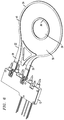
- FIG. 1 is an isometric diagram of an exemplary optical fiber amplifier, formed in accordance with the present invention
- FIG. 2 is an exploded view of the optical fiber amplifier of FIG. 1 ;
- FIG. 3 depicts a section of amplifying fiber, presented as a flat coil for use within the fiber module of the amplifier;
- FIG. 4 illustrates the coil of amplifying fiber of FIG. 3 as disposed on an exemplary fiber module
- FIG. 5 is a diagram of the support structure portion of the fiber module, illustrating the parameters that control the bend radius experienced by the amplifying fiber as it is coiled;
- FIG. 6 illustrates an alternative configuration for attaching the fiber module to the optics module of the inventive optical amplifier
- FIG. 7 shows a compact configuration where the electrical isolation provided by the material of the fiber module allows for an electronic circuit board to be positioned in close proximity to the optical amplifier;
- FIG. 8 is an exploded view of an alternative embodiment of a fiber module formed in accordance with the present invention.
- FIG. 9 is an isometric view of the fiber module of FIG. 8 ;
- FIG. 10 is a cut-away side view of a portion of the fiber module of FIG. 9 ;
- FIG. 11 illustrates an exemplary set of three fiber coils that may be housed within the fiber module of FIG. 8 ;
- FIG. 12 shows a first fiber coil as positioned with the fiber module
- FIG. 13 shows a final assembly, with a pair of fiber splice coils disposed in an outer portion of the fiber module, separate from the primary fiber coil.
- FIG. 14 is an exploded view showing an outer cover to be placed over the module of FIG. 13 ;
- FIG. 15 illustrates the exemplary fiber module of FIG. 9 with the outer cover in place
- FIG. 16 illustrates an alternative geometry of a central bobbin that may be used within a fiber support structure in accordance with the present invention.
- FIG. 17 illustrates an alternative geometry of an outer boundary element that may be used within a fiber support structure in accordance with the present invention.
- FIG. 1 is an isometric diagram of an exemplary compact optical amplifier 10 , formed in accordance with the present invention.
- Optical amplifier 10 comprises both an optics module 12 and an amplifying fiber module 14 .
- Optics module 12 is of conventional form perhaps, and includes various optical elements, hybrids, etc. utilized to create an amplified output signal that meets defined system requirements (in terms of, for example, noise floor, isolation, gain profile, insertion loss, etc.).
- Fiber module 14 houses a (relatively long) section of amplifying fiber that is used to perform the actual amplification function on the incoming optical signal.
- There exist many different configurations that may be used to provide the optical functions as required within optics module 12 where co-pending U.S. application Ser. No. 15/072,520 (filed Mar. 17, 2016) describes some preferred embodiments and is herein incorporated by reference.
- fiber module 14 is shown in FIG. 1 without having the amplifying fiber in place. It is to be understood that when designing a rare-earth doped fiber amplifier, a section of doped fiber (e.g., erbium-doped fiber) would be placed within fiber module 14 . For the case of a distributed Raman amplifier, a section of conventional single-mode fiber is typically disposed within fiber module 14 . An exemplary process of loading the amplifying fiber into module 14 will be described below in association with FIGS. 3-5 .
- FIG. 2 is another view of exemplary compact optical amplifier 10 , in this case an exploded view with optics module 12 shown as separated from fiber module 14 , and a set of exemplary components forming fiber module 14 also shown.
- an incoming optical signal is introduced in optics module 12 via a fiber pigtail connection 16 .
- the incoming optical signal and pump light (which may be supplied from a separate external source or co-packaged within optics module 12 ) are combined within optics module 12 and coupled into fiber module 14 via a pigtail fiber connection 17 .
- the optical signal and pump light then propagate through the length of amplifying fiber 20 housed with fiber module 14 , with an amplified version of the optical signal ultimately exiting fiber module 14 .
- the amplified signal is then coupled back into optics module 12 at an optical fiber pigtail 18 .
- Various post-amplification optical functions are performed on the signal, which then exits optics module 12 from optical fiber pigtail 19 as the amplified output signal from optical amplifier 10 .
- fiber module 14 is shown as comprising a stiff support member 22 configured to have a relatively circular distal portion 24 and an opposing pair of end terminations 26 and 28 that are used to attach fiber module 14 to optics module 12 .
- a flexible substrate 30 of a suitable insulative material e.g., a polyimide-based material
- a coating 31 of a pressure-sensitive adhesive is applied to flexible substrate 30 .
- the adhesive coating is used to ensure the integrity of the attachment of amplifying fiber 20 to flexible substrate 30 .
- a top cover plate 32 and a bottom cover plate 34 used to encase amplifying fiber 20 within fiber module 14 (as shown in final form in FIG. 1 ).
- Variations of this specific configuration are contemplated, including the use of fewer or more end terminations to mechanically attach fiber module 14 to optics module 12 . Additionally, while it may be preferred to include an adhesive coating 31 on flexible material 30 , there may be some types of flexible material that exhibit an adhesive nature without the need for the additional coating.
- One aspect of the present invention is the particular configuration of the amplifying fiber as a flat coil (as compared with bundling the fiber as is common in the prior art).
- amplifying fiber 20 is shown as being coiled in a manner that creates a “stack” of two flat coils shown as 20 - 1 and 20 - 1 .
- FIG. 4 illustrates a coil of amplifying fiber 20 as in place within circular portion 24 of support structure 22 .
- the amplifying fiber is literally spun onto flexible material 30 , using a pressure sufficient to allow for adhesive coating 31 to hold the coiled fiber in place.
- amplifying fiber 20 comprises a section of rare-earth doped fiber about one meter in length (at times, more than a meter may be required).
- DRAs may utilize conventional signal mode optical fibers of lengths of several meters in the formation of amplifying fiber 20 .
- bend loss In attempting to incorporate these relatively long lengths of amplifying fiber within packages of relatively small dimensions, it is necessary to understand the impact of bend loss on the propagating signal. That is, if a fiber is bent into a curve (in this case, when forming a coil) with a very tight bend radius, a large fraction of the propagating signal will be scattered out of the core region; the loss increases as the fiber radius decreases. A very small fiber bend radius may also cause breakage of the fiber itself.
- the bend radius is maintained at a large value (i.e., such that only a relatively “gentle” bend is imparted on the fiber)
- the size of a package required to accommodate a meter or two of amplifying fiber would be too large for many of the CFP requirements.
- FIG. 5 is a diagram of an exemplary support structure 22 formed in accordance with these aspects of the present invention to control the curvature introduced into the coil configuration of amplifying fiber 20 .
- circular portion 24 of support structure 22 is shown as including a central opening 36 , where the diameter d of opening 36 is chosen to prevent amplifying fiber 20 from being coiled with a very tight bend radius.
- the outer diameter D of circular portion 24 is chosen to ensure that the final dimensions of optical amplifier 10 are well within the limitations imposed by the particular package design.
- Opening 36 may include a rim 38 to prevent the amplifying fiber from entering this central area.
- the outer periphery of support structure 22 may include a rim 40 to maintain the fiber confined within its designated boundary.
- amplifying fiber 20 is spun onto the surface flexible substrate 30 of support structure 22 , using opening 36 (with rim 38 ) and outer rim 40 as guides for the process. That is, amplifying fiber 20 is spooled in a flat configuration, rather than bundled as in the prior art, with miniature splice protectors inserted in place for connection to fiber pigtails 17 and 18 . As such, this portion of the optical amplifier may be assembled with automated methods, making a highly repeatable process with high yield and low cost, as well as a small footprint.
- FIGS. 1 and 2 utilizes a straightforward snap-fit friction fitting between end terminations 26 , 28 of fiber module 14 and associated attachment elements 42 , 44 formed within the housing 46 of optics module 12 (best shown in FIG. 2 ).
- FIG. 6 is an isometric view of an alternative attachment configuration, in this case using a set of screws 48 to attach end terminations 26 , 28 of fiber module 14 to housing 46 of optics module 12 .
- the specifics of rims 38 and 40 are also specifically shown in this view of the inventive compact optical amplifier module. from underneath optical amplifier 10 , showing the attachment of fiber module 14 to optics module 12 . In this view, both end terminations 26 and 28 are visible, with stiffening elements 42 and 42 ′ disposed as shown.
- Attachment screws 50 and 52 are shown as attaching end termination 26 to optics module 12 , with similar attachment screws 50 ′ and 52 ′ used to attach end termination 28 .
- FIG. 7 is an exemplary illustration of the inventive compact optical amplifier that illustrates this aspect.
- the covering layer enclosing amplifying fiber 20 is not shown.
- an electronics circuit board 100 is illustrated as being disposed directly underneath compact optical amplifier 10 , extending beneath both optics module 12 and fiber module 14 .
- inventive fiber module for use with a fiber-based optical amplifier may be used in the formation of a doped fiber amplifier (such as an EDFA) or a distributed Raman amplifier, with the only change in assembly being the type of fiber that is spooled onto the flexible substrate of the module.
- a doped fiber amplifier such as an EDFA
- a distributed Raman amplifier with the only change in assembly being the type of fiber that is spooled onto the flexible substrate of the module.
- the particular dimensions of support structure 22 may differ as a function of a minimum bend radius associated with a particular amplifier's design criteria.
- FIG. 8 illustrates another embodiment of a low-profile structure for enclosing and supporting one or more coils of optical fiber, particularly suitable for use with an optical amplifier or any other fiber-based device.
- Fiber support structure 80 is shown in an exploded view in FIG. 8 , and in an assembled form in FIG. 9 .
- fiber support structure 80 includes a containment component formed of an outer boundary element 82 and a bobbin 83 , where bobbin 83 is disposed within an inner area of outer boundary element 82 .
- the dimensions of bobbin 83 define the minimum bend radius permitted for a coil of fiber disposed within fiber support structure 80 and wound around bobbin 83 .
- outer boundary element 82 may be formed to include fiber lead-ins 84 and 86 .
- Outer boundary element 82 and bobbin 83 may be formed of any suitable material, including relatively stiff plastic materials.
- a first sheet of plastic material 90 (e.g., polyimide, polycarbonate, or the like) is attached around a bottom surface 82 B of outer boundary element 82 and a bottom surface 83 B of bobbin 83 B.
- This first sheet of plastic material is defined hereinafter as “bottom sheet 90 ” of fiber support structure 80 .
- Fiber coil 20 is disposed upon bottom sheet 90 , with the diameter of fiber coil 20 being less than the inner diameter of outer boundary element 82 .
- a second, top sheet of plastic material 92 (formed of the same or similar material as bottom sheet 90 ) is then disposed to cover a top surface 82 T of outer boundary element 82 .
- Sheets 90 and 92 may be welded to outer boundary element 82 (e.g., ultrasonic, thermal or chemical welding) or otherwise adhered to the ring.
- top sheet 92 may comprise a predetermined width W that allows for top sheet 92 to slightly overhang an inner surface 821 of outer boundary element 82 .
- FIG. 10 is a cut-away side view of a portion of the configuration of FIG. 9 , illustrating an overhang D of top sheet 92 with respect to inner surface 821 of outer boundary element 82 and bottom sheet 90 .
- Overhang D is designed to create a covered outer portion of fiber support structure 80 that extends for a width that is slightly longer than at least two fiber diameters, as shown in FIG. 10 .
- This configuration allows for spliced portion of the fibers to be inserted underneath the overhang, as will be described below.
- features such as slots or cuts can be included in the overhanging portion of top sheet 92 to allow fibers to escape the structure in a controlled fashion, as may be desirable during assembly operations.
- FIG. 11 illustrates a set of fibers that may be housed within fiber support structure 80 .
- FIG. 12 shows fiber coil 20 as positioned on bottom sheet 90 of fiber support structure 80 , prior to positioning fiber splices 20 - 1 and 20 - 2 within an outer portion of fiber structure 80 underneath the overhang created by top sheet 92 . It is to be understood that a fiber coil is not necessarily planar, or may include a plurality of planar coils that are positioned in a stacked configuration around bobbin 83 of fiber support structure 80 .
- the lengths of fiber splices 20 - 1 and 20 - 2 which extend from pre-made coil 20 are controlled to a precision that ensures that the splices will naturally fall at a predetermined location within fiber support structure 80 that is selected for minimal stress on the fiber, which in turn results in high reliability.
- the lengths are further specified such that, when the fiber is folded and looped to ever-smaller coils until they fit into the reserved outer portion of the structure. Therefore, the fiber achieves a minimum stress condition (i.e., there are no residual stresses in the fiber that would otherwise result from twists if the lengths were uncontrolled or poorly controlled).
- FIG. 13 illustrates fiber splices 20 - 1 and 20 - 2 as positioned within fiber support structure 80 .
- the loops of spliced fiber 20 - 1 and 20 - 2 naturally expand to fill the maximum diameter of the reserved portion of the structure. Therefore, the splices reside near the maximum available diameter (i.e., close to inner surface 821 of outer boundary element 82 ) and are subjected to the minimal possible bending stress in their final deployed state, ensuring high reliability and low insertion loss.
- top sheet 92 which allows splices 20 - 1 and 20 - 2 to be positioned underneath top sheet 92 and then positioned in place along on outer portion of bottom sheet 90 of fiber support structure, as described above.
- Slots 94 are also shown in this view, used to control the placement of splices 20 - 1 and 20 - 2 within fiber structure 80 .
- fiber support structure 80 may further include an outer cover to encase and protect the stored fiber coil 20 , as well as splices 20 - 1 and 20 - 2 (and/or any other fibers to be contained within support structure 80 ).
- FIG. 14 is an exploded view of an exemplary configuration, showing an outer cover 100 relative to fiber structure 80 . It is to be noted that fiber coil 20 , as well as splices 20 - 1 and 20 - 2 are not shown in this view.
- FIG. 15 is a final view, showing outer cover 100 in place over and attached to top sheet 92 of fiber structure 80 .
- FIGS. 8-15 illustrate the use of a circular outer boundary element 82 and bobbin 83
- other geometries may be employed, as long as the induced bend (curving) of the optical fiber around the bobbin is not greater than the minimal allowable bend radius.
- a somewhat rounded, triangular-shaped bobbin may be used, shown as bobbin 83 A in FIG. 16 .
- FIG. 17 is a top view of an exemplary fiber support structure 80 A, which in this case utilizes a non-circular outer boundary element 82 A (which is still configured to comply with minimum bend radius constraints for a given fiber in accordance with the present invention).
- an inner periphery 82 AI of outer boundary element 82 A is heptagonal in form, providing sufficient space for fiber coil 20 , while also having additional space for any fiber splices which may be added.
- the outer shape of outer boundary element 82 A may be any suitable form. In the particular configuration shown in FIG. 17 , the outer boundary is rectangular in form. In other cases, it may be circular, or may follow the heptagonal design of inner periphery 82 AI.
- the heptagonal geometry of outer boundary element 82 A should be considered as exemplary only; various other geometries may be used as long as they adhere to the bend radius requirements for a specific application.
Landscapes
- Physics & Mathematics (AREA)
- Electromagnetism (AREA)
- Engineering & Computer Science (AREA)
- Plasma & Fusion (AREA)
- Optics & Photonics (AREA)
- Microelectronics & Electronic Packaging (AREA)
- Lasers (AREA)
Abstract
Description
Claims (11)
Priority Applications (3)
| Application Number | Priority Date | Filing Date | Title |
|---|---|---|---|
| US15/648,885 US10749309B2 (en) | 2015-03-19 | 2017-07-13 | Compact optical fiber amplifier |
| JP2018095950A JP6586194B2 (en) | 2017-07-13 | 2018-05-18 | Compact optical fiber amplifier |
| CN201810763071.5A CN109256661B (en) | 2017-07-13 | 2018-07-12 | A compact fiber amplifier |
Applications Claiming Priority (3)
| Application Number | Priority Date | Filing Date | Title |
|---|---|---|---|
| US201562135641P | 2015-03-19 | 2015-03-19 | |
| US15/071,296 US9722387B2 (en) | 2015-03-19 | 2016-03-16 | Compact optical fiber amplifier |
| US15/648,885 US10749309B2 (en) | 2015-03-19 | 2017-07-13 | Compact optical fiber amplifier |
Related Parent Applications (1)
| Application Number | Title | Priority Date | Filing Date |
|---|---|---|---|
| US15/071,296 Continuation-In-Part US9722387B2 (en) | 2015-03-19 | 2016-03-16 | Compact optical fiber amplifier |
Publications (2)
| Publication Number | Publication Date |
|---|---|
| US20170317463A1 US20170317463A1 (en) | 2017-11-02 |
| US10749309B2 true US10749309B2 (en) | 2020-08-18 |
Family
ID=60158591
Family Applications (1)
| Application Number | Title | Priority Date | Filing Date |
|---|---|---|---|
| US15/648,885 Active 2037-02-24 US10749309B2 (en) | 2015-03-19 | 2017-07-13 | Compact optical fiber amplifier |
Country Status (1)
| Country | Link |
|---|---|
| US (1) | US10749309B2 (en) |
Families Citing this family (4)
| Publication number | Priority date | Publication date | Assignee | Title |
|---|---|---|---|---|
| WO2020205365A1 (en) * | 2019-03-29 | 2020-10-08 | Commscope Technologies Llc | Telecommunications module with improved fiber management features |
| CN110927902B (en) * | 2019-11-26 | 2021-02-02 | 烽火海洋网络设备有限公司 | Submarine remote pumping optical amplifier packaging structure |
| US11086077B1 (en) * | 2020-06-23 | 2021-08-10 | Ii-Vi Delaware, Inc. | Optical component arrays |
| US20220158488A1 (en) * | 2020-11-16 | 2022-05-19 | Tc1 Llc | Wireless power transmission device holder and method for making the same |
Citations (20)
| Publication number | Priority date | Publication date | Assignee | Title |
|---|---|---|---|---|
| US4984685A (en) * | 1990-01-02 | 1991-01-15 | Douglas Frank A | Portable container for elongated elements |
| US5103977A (en) * | 1990-01-02 | 1992-04-14 | Douglas Frank A | Portable container for elongated elements |
| US5469526A (en) * | 1994-01-07 | 1995-11-21 | Porta Systems Corp. | Optical fiber support for printed circuit boards |
| US5726796A (en) | 1995-05-17 | 1998-03-10 | Alcatel N.V. | Optical amplifier |
| US5917648A (en) * | 1994-06-22 | 1999-06-29 | Hewlett-Packard Company | Packaged optical amplifier assembly |
| US6144792A (en) * | 1996-10-25 | 2000-11-07 | Samsung Electronics Co., Ltd. | Device for fixing the optical elements of an optical fiber amplifier |
| WO2001076022A2 (en) | 2000-04-03 | 2001-10-11 | Corona Optical Systems, Inc. | Optical amplifier |
| US6334020B1 (en) * | 1999-09-30 | 2001-12-25 | The Boeing Company | Compact package structure for fiber optic devices |
| US6412701B1 (en) | 1997-05-19 | 2002-07-02 | Hitachi Maxell, Ltd. | Flexible IC module and method of its manufacture, and method of manufacturing information carrier comprising flexible IC module |
| US20030044141A1 (en) | 2001-08-31 | 2003-03-06 | Melton Stuart R. | Optical interconnect assemblies and methods therefor |
| US6567600B2 (en) | 2000-03-08 | 2003-05-20 | Nec Corporation | Optical amplifying medium component and optical fiber amplifier having the same |
| US6636685B2 (en) | 2002-01-30 | 2003-10-21 | Fitel Usa Corp. | Systems and methods for fabricating flexible optical fiber circuits |
| US20050018950A1 (en) | 2002-04-22 | 2005-01-27 | Sanmina-Sci Corporation | Temperature-controlled flexible optical circuit for use in an erbium-doped fiber amplifier and method for fabricating the flexible optical circuit |
| US6917731B2 (en) | 2002-03-27 | 2005-07-12 | Corning Incorporated | Optical amplification module |
| US6937385B2 (en) | 2002-03-27 | 2005-08-30 | Avanex Corporation | Customer interface module |
| EP1569308A1 (en) | 2002-12-06 | 2005-08-31 | Central Glass Company, Limited | Fiber optic amplifier module |
| US7899296B2 (en) | 2007-06-21 | 2011-03-01 | Fujitsu Limited | Optical fiber reel |
| US20130077913A1 (en) | 2011-09-23 | 2013-03-28 | Tyco Electronics Nederland Bv | Flexible optical circuit |
| US20160124171A1 (en) * | 2014-10-30 | 2016-05-05 | Fujikura, Ltd. | Housing case for optical fiber |
| US20160274321A1 (en) | 2015-03-21 | 2016-09-22 | Ii-Vi Incorporated | Flexible Structured Optical Modules |
-
2017
- 2017-07-13 US US15/648,885 patent/US10749309B2/en active Active
Patent Citations (21)
| Publication number | Priority date | Publication date | Assignee | Title |
|---|---|---|---|---|
| US5103977A (en) * | 1990-01-02 | 1992-04-14 | Douglas Frank A | Portable container for elongated elements |
| US4984685A (en) * | 1990-01-02 | 1991-01-15 | Douglas Frank A | Portable container for elongated elements |
| US5469526A (en) * | 1994-01-07 | 1995-11-21 | Porta Systems Corp. | Optical fiber support for printed circuit boards |
| US5917648A (en) * | 1994-06-22 | 1999-06-29 | Hewlett-Packard Company | Packaged optical amplifier assembly |
| US5726796A (en) | 1995-05-17 | 1998-03-10 | Alcatel N.V. | Optical amplifier |
| US6144792A (en) * | 1996-10-25 | 2000-11-07 | Samsung Electronics Co., Ltd. | Device for fixing the optical elements of an optical fiber amplifier |
| US6412701B1 (en) | 1997-05-19 | 2002-07-02 | Hitachi Maxell, Ltd. | Flexible IC module and method of its manufacture, and method of manufacturing information carrier comprising flexible IC module |
| US6334020B1 (en) * | 1999-09-30 | 2001-12-25 | The Boeing Company | Compact package structure for fiber optic devices |
| US6567600B2 (en) | 2000-03-08 | 2003-05-20 | Nec Corporation | Optical amplifying medium component and optical fiber amplifier having the same |
| WO2001076022A2 (en) | 2000-04-03 | 2001-10-11 | Corona Optical Systems, Inc. | Optical amplifier |
| US20030044141A1 (en) | 2001-08-31 | 2003-03-06 | Melton Stuart R. | Optical interconnect assemblies and methods therefor |
| US6636685B2 (en) | 2002-01-30 | 2003-10-21 | Fitel Usa Corp. | Systems and methods for fabricating flexible optical fiber circuits |
| US6917731B2 (en) | 2002-03-27 | 2005-07-12 | Corning Incorporated | Optical amplification module |
| US6937385B2 (en) | 2002-03-27 | 2005-08-30 | Avanex Corporation | Customer interface module |
| US20050018950A1 (en) | 2002-04-22 | 2005-01-27 | Sanmina-Sci Corporation | Temperature-controlled flexible optical circuit for use in an erbium-doped fiber amplifier and method for fabricating the flexible optical circuit |
| EP1569308A1 (en) | 2002-12-06 | 2005-08-31 | Central Glass Company, Limited | Fiber optic amplifier module |
| US7899296B2 (en) | 2007-06-21 | 2011-03-01 | Fujitsu Limited | Optical fiber reel |
| US20130077913A1 (en) | 2011-09-23 | 2013-03-28 | Tyco Electronics Nederland Bv | Flexible optical circuit |
| US9031360B2 (en) | 2011-09-23 | 2015-05-12 | Tyco Electronics Nederland Bv | Flexible optical circuit |
| US20160124171A1 (en) * | 2014-10-30 | 2016-05-05 | Fujikura, Ltd. | Housing case for optical fiber |
| US20160274321A1 (en) | 2015-03-21 | 2016-09-22 | Ii-Vi Incorporated | Flexible Structured Optical Modules |
Also Published As
| Publication number | Publication date |
|---|---|
| US20170317463A1 (en) | 2017-11-02 |
Similar Documents
| Publication | Publication Date | Title |
|---|---|---|
| US10749309B2 (en) | Compact optical fiber amplifier | |
| JP3138244B2 (en) | Optical fiber amplifier packaging structure | |
| US7548679B2 (en) | Container for accommodating optical fiber coil and optical fiber module having the container | |
| US8743454B2 (en) | Multi-fibre arrangement for high power fibre lasers and amplifiers | |
| US5703990A (en) | Apparatus for housing a linearized optical fiber amplifier | |
| US7899296B2 (en) | Optical fiber reel | |
| US6072931A (en) | Fiber amplifier packaging apparatus | |
| JP3619139B2 (en) | Small package structure for optical fiber equipment | |
| US8682126B2 (en) | Method for assembling high power fiber laser system and module realizing the method | |
| US9722387B2 (en) | Compact optical fiber amplifier | |
| JPH0955556A (en) | Optical amplifier module | |
| JP6586194B2 (en) | Compact optical fiber amplifier | |
| CN104170186B (en) | Amplifying device and amplification medium | |
| AU713819B2 (en) | Apparatus and method for housing high-heat-emission electrooptical components | |
| CN112751253A (en) | Signal light high-order mode filtering method, high-order mode filtering amplification light path and laser | |
| US6829426B1 (en) | Flexible optical circuit for use in an erbium-doped fiber amplifier and method for fabricating the flexible optical circuit | |
| JP2004133056A (en) | Optical module and method of manufacturing the same | |
| JP3513791B2 (en) | Optical fiber coil housing case and extra length processing case for housing it | |
| JPH04253037A (en) | Multifiber optical amplifier and structure for connecting multiple optical fiber using this amplifier | |
| JP2001133635A (en) | Optical fiber module | |
| JP2013076835A (en) | Storage substrate for optical fiber, optical module including storage substrate for optical fiber, and storage box including storage substrate for optical fiber |
Legal Events
| Date | Code | Title | Description |
|---|---|---|---|
| AS | Assignment |
Owner name: II-VI INCORPORATED, PENNSYLVANIA Free format text: ASSIGNMENT OF ASSIGNORS INTEREST;ASSIGNORS:GREEN, ERIC TIMOTHY;MYERS, DANIEL CHRISTOPHER;STARNER, TODD GREGORY;AND OTHERS;SIGNING DATES FROM 20170710 TO 20170713;REEL/FRAME:042999/0406 |
|
| STPP | Information on status: patent application and granting procedure in general |
Free format text: DOCKETED NEW CASE - READY FOR EXAMINATION |
|
| AS | Assignment |
Owner name: II-VI DELAWARE, INC., DELAWARE Free format text: ASSIGNMENT OF ASSIGNORS INTEREST;ASSIGNOR:II-VI INCORPORATED;REEL/FRAME:048631/0234 Effective date: 20190311 |
|
| STPP | Information on status: patent application and granting procedure in general |
Free format text: NON FINAL ACTION MAILED |
|
| AS | Assignment |
Owner name: BANK OF AMERICA, N.A., AS ADMINISTRATIVE AGENT, NO Free format text: NOTICE OF GRANT OF SECURITY INTEREST IN PATENTS;ASSIGNORS:II-VI INCORPORATED;MARLOW INDUSTRIES, INC.;EPIWORKS, INC.;AND OTHERS;REEL/FRAME:050484/0204 Effective date: 20190924 Owner name: BANK OF AMERICA, N.A., AS ADMINISTRATIVE AGENT, NORTH CAROLINA Free format text: NOTICE OF GRANT OF SECURITY INTEREST IN PATENTS;ASSIGNORS:II-VI INCORPORATED;MARLOW INDUSTRIES, INC.;EPIWORKS, INC.;AND OTHERS;REEL/FRAME:050484/0204 Effective date: 20190924 |
|
| STPP | Information on status: patent application and granting procedure in general |
Free format text: RESPONSE TO NON-FINAL OFFICE ACTION ENTERED AND FORWARDED TO EXAMINER |
|
| STPP | Information on status: patent application and granting procedure in general |
Free format text: NOTICE OF ALLOWANCE MAILED -- APPLICATION RECEIVED IN OFFICE OF PUBLICATIONS |
|
| STPP | Information on status: patent application and granting procedure in general |
Free format text: PUBLICATIONS -- ISSUE FEE PAYMENT RECEIVED |
|
| STCB | Information on status: application discontinuation |
Free format text: ABANDONED -- FAILURE TO PAY ISSUE FEE |
|
| STPP | Information on status: patent application and granting procedure in general |
Free format text: PUBLICATIONS -- ISSUE FEE PAYMENT VERIFIED |
|
| STCF | Information on status: patent grant |
Free format text: PATENTED CASE |
|
| AS | Assignment |
Owner name: JPMORGAN CHASE BANK, N.A., AS COLLATERAL AGENT, NEW YORK Free format text: SECURITY INTEREST;ASSIGNORS:II-VI INCORPORATED;II-VI DELAWARE, INC.;M CUBED TECHNOLOGIES, INC.;AND OTHERS;REEL/FRAME:060562/0254 Effective date: 20220701 |
|
| AS | Assignment |
Owner name: PHOTOP TECHNOLOGIES, INC., CALIFORNIA Free format text: PATENT RELEASE AND REASSIGNMENT;ASSIGNOR:BANK OF AMERICA, N.A., AS ADMINISTRATIVE AGENT;REEL/FRAME:060574/0001 Effective date: 20220701 Owner name: II-VI OPTOELECTRONIC DEVICES, INC., NEW JERSEY Free format text: PATENT RELEASE AND REASSIGNMENT;ASSIGNOR:BANK OF AMERICA, N.A., AS ADMINISTRATIVE AGENT;REEL/FRAME:060574/0001 Effective date: 20220701 Owner name: II-VI DELAWARE, INC., PENNSYLVANIA Free format text: PATENT RELEASE AND REASSIGNMENT;ASSIGNOR:BANK OF AMERICA, N.A., AS ADMINISTRATIVE AGENT;REEL/FRAME:060574/0001 Effective date: 20220701 Owner name: II-VI PHOTONICS (US), INC., MASSACHUSETTS Free format text: PATENT RELEASE AND REASSIGNMENT;ASSIGNOR:BANK OF AMERICA, N.A., AS ADMINISTRATIVE AGENT;REEL/FRAME:060574/0001 Effective date: 20220701 Owner name: M CUBED TECHNOLOGIES, INC., CONNECTICUT Free format text: PATENT RELEASE AND REASSIGNMENT;ASSIGNOR:BANK OF AMERICA, N.A., AS ADMINISTRATIVE AGENT;REEL/FRAME:060574/0001 Effective date: 20220701 Owner name: II-VI OPTICAL SYSTEMS, INC., CALIFORNIA Free format text: PATENT RELEASE AND REASSIGNMENT;ASSIGNOR:BANK OF AMERICA, N.A., AS ADMINISTRATIVE AGENT;REEL/FRAME:060574/0001 Effective date: 20220701 Owner name: FINISAR CORPORATION, CALIFORNIA Free format text: PATENT RELEASE AND REASSIGNMENT;ASSIGNOR:BANK OF AMERICA, N.A., AS ADMINISTRATIVE AGENT;REEL/FRAME:060574/0001 Effective date: 20220701 Owner name: OPTIUM CORPORATION, CALIFORNIA Free format text: PATENT RELEASE AND REASSIGNMENT;ASSIGNOR:BANK OF AMERICA, N.A., AS ADMINISTRATIVE AGENT;REEL/FRAME:060574/0001 Effective date: 20220701 Owner name: COADNA PHOTONICS, INC., PENNSYLVANIA Free format text: PATENT RELEASE AND REASSIGNMENT;ASSIGNOR:BANK OF AMERICA, N.A., AS ADMINISTRATIVE AGENT;REEL/FRAME:060574/0001 Effective date: 20220701 Owner name: KAILIGHT PHOTONICS, INC., CALIFORNIA Free format text: PATENT RELEASE AND REASSIGNMENT;ASSIGNOR:BANK OF AMERICA, N.A., AS ADMINISTRATIVE AGENT;REEL/FRAME:060574/0001 Effective date: 20220701 Owner name: LIGHTSMYTH TECHNOLOGIES, INC., OREGON Free format text: PATENT RELEASE AND REASSIGNMENT;ASSIGNOR:BANK OF AMERICA, N.A., AS ADMINISTRATIVE AGENT;REEL/FRAME:060574/0001 Effective date: 20220701 Owner name: EPIWORKS, INC., ILLINOIS Free format text: PATENT RELEASE AND REASSIGNMENT;ASSIGNOR:BANK OF AMERICA, N.A., AS ADMINISTRATIVE AGENT;REEL/FRAME:060574/0001 Effective date: 20220701 Owner name: MARLOW INDUSTRIES, INC., TEXAS Free format text: PATENT RELEASE AND REASSIGNMENT;ASSIGNOR:BANK OF AMERICA, N.A., AS ADMINISTRATIVE AGENT;REEL/FRAME:060574/0001 Effective date: 20220701 Owner name: II-VI INCORPORATED, PENNSYLVANIA Free format text: PATENT RELEASE AND REASSIGNMENT;ASSIGNOR:BANK OF AMERICA, N.A., AS ADMINISTRATIVE AGENT;REEL/FRAME:060574/0001 Effective date: 20220701 |
|
| MAFP | Maintenance fee payment |
Free format text: PAYMENT OF MAINTENANCE FEE, 4TH YEAR, LARGE ENTITY (ORIGINAL EVENT CODE: M1551); ENTITY STATUS OF PATENT OWNER: LARGE ENTITY Year of fee payment: 4 |