US10746414B2 - Flue vent adapter for multi-poise furnace - Google Patents
Flue vent adapter for multi-poise furnace Download PDFInfo
- Publication number
- US10746414B2 US10746414B2 US15/582,299 US201715582299A US10746414B2 US 10746414 B2 US10746414 B2 US 10746414B2 US 201715582299 A US201715582299 A US 201715582299A US 10746414 B2 US10746414 B2 US 10746414B2
- Authority
- US
- United States
- Prior art keywords
- flue vent
- furnace
- transition
- outlet
- shape
- Prior art date
- Legal status (The legal status is an assumption and is not a legal conclusion. Google has not performed a legal analysis and makes no representation as to the accuracy of the status listed.)
- Active, expires
Links
- 239000000411 inducer Substances 0.000 claims abstract description 45
- 230000007704 transition Effects 0.000 claims description 101
- 239000011324 bead Substances 0.000 claims description 9
- 238000004519 manufacturing process Methods 0.000 abstract description 6
- 238000010276 construction Methods 0.000 abstract description 2
- 238000000034 method Methods 0.000 description 14
- 239000007789 gas Substances 0.000 description 10
- 239000012530 fluid Substances 0.000 description 9
- 239000000446 fuel Substances 0.000 description 8
- 238000005192 partition Methods 0.000 description 6
- 239000000203 mixture Substances 0.000 description 5
- 238000005452 bending Methods 0.000 description 3
- 238000004891 communication Methods 0.000 description 3
- 238000009434 installation Methods 0.000 description 3
- 238000013461 design Methods 0.000 description 2
- 238000010438 heat treatment Methods 0.000 description 2
- 239000000463 material Substances 0.000 description 2
- 230000008569 process Effects 0.000 description 2
- 238000004378 air conditioning Methods 0.000 description 1
- 230000000712 assembly Effects 0.000 description 1
- 238000000429 assembly Methods 0.000 description 1
- 230000004888 barrier function Effects 0.000 description 1
- 230000000295 complement effect Effects 0.000 description 1
- 230000001143 conditioned effect Effects 0.000 description 1
- 230000003750 conditioning effect Effects 0.000 description 1
- 238000011161 development Methods 0.000 description 1
- 238000005553 drilling Methods 0.000 description 1
- 239000003546 flue gas Substances 0.000 description 1
- 238000012986 modification Methods 0.000 description 1
- 230000004048 modification Effects 0.000 description 1
- 238000011160 research Methods 0.000 description 1
- 238000009966 trimming Methods 0.000 description 1
- 238000009423 ventilation Methods 0.000 description 1
- 230000037303 wrinkles Effects 0.000 description 1
Images


Classifications
-
- F—MECHANICAL ENGINEERING; LIGHTING; HEATING; WEAPONS; BLASTING
- F24—HEATING; RANGES; VENTILATING
- F24D—DOMESTIC- OR SPACE-HEATING SYSTEMS, e.g. CENTRAL HEATING SYSTEMS; DOMESTIC HOT-WATER SUPPLY SYSTEMS; ELEMENTS OR COMPONENTS THEREFOR
- F24D5/00—Hot-air central heating systems; Exhaust gas central heating systems
- F24D5/02—Hot-air central heating systems; Exhaust gas central heating systems operating with discharge of hot air into the space or area to be heated
-
- F—MECHANICAL ENGINEERING; LIGHTING; HEATING; WEAPONS; BLASTING
- F23—COMBUSTION APPARATUS; COMBUSTION PROCESSES
- F23J—REMOVAL OR TREATMENT OF COMBUSTION PRODUCTS OR COMBUSTION RESIDUES; FLUES
- F23J11/00—Devices for conducting smoke or fumes, e.g. flues
-
- F—MECHANICAL ENGINEERING; LIGHTING; HEATING; WEAPONS; BLASTING
- F23—COMBUSTION APPARATUS; COMBUSTION PROCESSES
- F23J—REMOVAL OR TREATMENT OF COMBUSTION PRODUCTS OR COMBUSTION RESIDUES; FLUES
- F23J13/00—Fittings for chimneys or flues
- F23J13/04—Joints; Connections
-
- F—MECHANICAL ENGINEERING; LIGHTING; HEATING; WEAPONS; BLASTING
- F24—HEATING; RANGES; VENTILATING
- F24D—DOMESTIC- OR SPACE-HEATING SYSTEMS, e.g. CENTRAL HEATING SYSTEMS; DOMESTIC HOT-WATER SUPPLY SYSTEMS; ELEMENTS OR COMPONENTS THEREFOR
- F24D5/00—Hot-air central heating systems; Exhaust gas central heating systems
- F24D5/02—Hot-air central heating systems; Exhaust gas central heating systems operating with discharge of hot air into the space or area to be heated
- F24D5/04—Hot-air central heating systems; Exhaust gas central heating systems operating with discharge of hot air into the space or area to be heated with return of the air or the air-heater
-
- F—MECHANICAL ENGINEERING; LIGHTING; HEATING; WEAPONS; BLASTING
- F24—HEATING; RANGES; VENTILATING
- F24H—FLUID HEATERS, e.g. WATER OR AIR HEATERS, HAVING HEAT-GENERATING MEANS, e.g. HEAT PUMPS, IN GENERAL
- F24H3/00—Air heaters
- F24H3/02—Air heaters with forced circulation
- F24H3/06—Air heaters with forced circulation the air being kept separate from the heating medium, e.g. using forced circulation of air over radiators
- F24H3/065—Air heaters with forced circulation the air being kept separate from the heating medium, e.g. using forced circulation of air over radiators using fluid fuel
-
- F—MECHANICAL ENGINEERING; LIGHTING; HEATING; WEAPONS; BLASTING
- F24—HEATING; RANGES; VENTILATING
- F24H—FLUID HEATERS, e.g. WATER OR AIR HEATERS, HAVING HEAT-GENERATING MEANS, e.g. HEAT PUMPS, IN GENERAL
- F24H9/00—Details
- F24H9/0052—Details for air heaters
- F24H9/0057—Guiding means
- F24H9/0068—Guiding means in combustion gas channels
-
- F—MECHANICAL ENGINEERING; LIGHTING; HEATING; WEAPONS; BLASTING
- F23—COMBUSTION APPARATUS; COMBUSTION PROCESSES
- F23J—REMOVAL OR TREATMENT OF COMBUSTION PRODUCTS OR COMBUSTION RESIDUES; FLUES
- F23J2900/00—Special arrangements for conducting or purifying combustion fumes; Treatment of fumes or ashes
- F23J2900/13022—Manufacturing processes for the lining of conducting means, e.g. by extrusion
Definitions
- Heating, ventilation, and/or air conditioning (HVAC) systems often include a furnace in many commercial and residential applications for heating and otherwise conditioning interior spaces. Installation of a furnace requires connecting an inducer blower of the furnace to a flue vent to carry and/or vent combusted flue gases from the structure in which the furnace is installed.
- HVAC Heating, ventilation, and/or air conditioning
- a flue vent adapter for a furnace comprising: a furnace cabinet; an inducer blower; flue vent transition; and a flue vent adapter comprising: an inlet; an outlet; and a substantially 90 degree bend disposed between the inlet and the outlet; wherein the flue vent adapter is connected between the inducer blower and the flue vent transition that is connected to a flue vent when the furnace is configured in a downflow orientation.
- a furnace comprising: an inlet; an outlet; and a substantially 90 degree bend disposed between the inlet and the outlet; wherein the flue vent adapter is connected between the inducer blower and the flue vent transition that is connected to a flue vent when the furnace is configured in a downflow orientation.
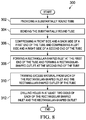
- a method of manufacturing a flue vent adapter for a furnace comprising: providing a substantially round tube; forming a bend in the substantially round tube; compressing a front side and a back side of a first end of the tube and compressing a left side and a right side of a second end of the tube; forming an elliptical portion near the second end of the tube; and forming a rectangular-shaped inlet at the first end of the tube and forming an outlet at the second end of the tube.
- FIG. 1 is a front view of a furnace configured in a horizontal left flow orientation according to an embodiment of the disclosure
- FIG. 2 is a front view of the furnace of FIG. 1 configured in a horizontal right flow orientation according to an embodiment of the disclosure
- FIG. 3 is a front view of the furnace of FIGS. 1 and 2 configured in an upflow orientation according to an embodiment of the disclosure
- FIG. 4 is a front view of the furnace of FIGS. 1-3 configured in a downflow orientation according to an embodiment of the disclosure
- FIG. 5 is a partial oblique view of the furnace of FIGS. 1-4 configured in the downflow orientation according to an embodiment of the disclosure
- FIG. 6 is a front view of the flue vent adapter of the furnace of FIGS. 1-5 according to an embodiment of the disclosure
- FIG. 7 is a left side view of the flue vent adapter of the furnace of FIGS. 1-5 according to an embodiment of the disclosure
- FIG. 8 is a flowchart of a method of manufacturing a flue vent adapter for a furnace according to an embodiment of the disclosure
- FIG. 9 is a front view of a furnace configured in the downflow orientation according to an alternative embodiment of the disclosure.
- FIG. 10 is a front view of the flue vent adapter of the furnace of FIG. 9 according to an alternative embodiment of the disclosure.
- FIG. 11 is a left side view of a flue vent adapter according to an alternative embodiment of the disclosure.
- Furnace 100 generally comprises a front side 102 , a back side 104 , a top side 106 , a bottom side 108 , a left side 110 , and a right side 112 .
- Such directional descriptions are meant to assist the reader in understanding the physical orientation of the various components of the furnace 100 .
- Furnace 100 comprises a furnace cabinet 114 , a partition panel 116 , a gas inlet 118 , an inducer blower 120 having an exhaust outlet 122 , a burner 124 configured to receive a flow of fuel through the gas inlet 118 , and a cold header 126 configured to mount the inducer blower 120 to the partition panel 116 and/or the furnace 100 .
- the furnace 100 comprises a non-condensing gas furnace and comprises at least one primary heat exchanger (not shown, view obstructed by partition panel 116 ) connected in fluid communication between the inducer blower 120 and the burner 124 .
- the furnace 100 may comprise a condensing gas furnace and comprise a secondary heat exchanger connected in fluid communication to the at least one primary heat exchanger via a hot header.
- Furnace 100 also comprises an interior space 128 accessible by opening a door and/or removing an outer panel of the furnace 100 , a flue vent transition 130 configured to connect the exhaust outlet 122 of the inducer blower 120 to at least one of a flue vent adapter 200 and a flue vent 150 , and at least one flue vent opening 140 to allow ingress and/or egress of the flue vent 150 through at least one side 102 , 104 , 106 , 108 , 110 , 112 of the furnace cabinet 114 of furnace 100 and into the interior space 128 of the furnace cabinet 114 of the furnace 100 .
- furnace 100 may also comprise a plurality of other components (e.g. gas inlet 118 regulator, inducer blower 120 controller, burner 124 controller, temperature sensors, pressure sensors, and or other control system hardware).
- the furnace 100 may generally comprise a four-walled fluid duct configured to receive an airflow therethrough.
- the partition panel 116 may generally provide a barrier between the four-walled fluid duct and the interior space 128 of the furnace 100 and be configured to provide a mounting surface for the cold header 126 that carries the inducer blower 120 .
- the burner 124 may be configured to receive a flow of fuel through the gas inlet 118 and combust an air/fuel mixture, while the inducer blower 120 draws the combusted and heated air/fuel mixture from the burner 124 through the heat exchanger to exchange heat with an airflow passing through the four-walled fluid duct portion of the furnace 100 .
- the heated airflow through the four-walled fluid duct portion of the furnace 100 may then be passed into an interior space of a structure in which the furnace 100 is installed to provide a temperature conditioned airflow into the interior space of the structure.
- the combusted air/fuel mixture may be drawn through the inducer blower 120 , where the combusted air/fuel mixture may exit the inducer blower 120 through the exhaust outlet 122 and out of the furnace cabinet 114 through the flue vent 150 .
- the inducer blower 120 may comprise a substantially rectangular-shaped exhaust outlet 122 .
- the flue vent transition 130 may generally comprise a substantially rectangular-shaped inlet of the flue vent transition 130 that attaches to the exhaust outlet 122 of the inducer blower 120 .
- the flue vent transition 130 may transition from the substantially rectangular-shaped inlet to a substantially round-shaped outlet of the flue vent transition 130 that attaches to the flue vent 150 .
- the substantially rectangular-shaped exhaust outlet 122 may be connected in fluid communication to the substantially round-shaped flue vent 150 via the flue vent transition 130 .
- the flue vent transition 130 may be configured to connect a flue vent adapter 200 that is connected to the exhaust outlet 122 of the inducer blower 120 to the flue vent 150 .
- the furnace 100 may generally comprise a multi-poise furnace and be configured to be installed and operated in each of the horizontal left flow orientation, the horizontal right flow orientation, the upflow orientation, and the downflow orientation.
- the inducer blower 120 may be mounted to the cold header 126 in a plurality of positions. More specifically, the inducer blower 120 may be rotated (at least in 90 degree increments) and mounted to the cold header 126 in at least four different positions to allow installation and operation of the furnace 100 in each of the horizontal left flow orientation, the horizontal right flow orientation, the upflow orientation, and the downflow orientation.
- the furnace 100 may comprise multiple flue vent openings 140 .
- the furnace cabinet 114 may comprise multiple flue vent opening 140 cutouts (shown specifically in FIG. 5 ).
- the cutouts for the multiple positions of the flue vent opening 140 may comprise scored areas, partially-milled outlines, at least partially punched and/or removed areas, and/or other features to allow easy removal of at least a portion of material of the furnace cabinet 114 to provide and/or form the flue vent opening 140 .
- the furnace cabinet 114 may comprise these features in each of the predetermined locations for the flue vent opening 140 for each of the furnace 100 orientations.
- the furnace 100 may generally be configured to be installed and operated in the horizontal left flow orientation.
- the furnace cabinet 114 may be oriented with the left side 110 of the furnace 100 facing in an upwards direction.
- the inducer blower 120 may be oriented with the exhaust outlet 122 of the inducer blower 120 facing the left side 110 of the furnace 100 .
- the flue vent opening 140 may be disposed in the left side 110 of the furnace cabinet 114 , and the flue vent 150 may enter the interior space 128 of the furnace cabinet 114 through the flue vent opening 140 .
- the furnace 100 may generally be configured to be installed and operated in the horizontal right flow orientation.
- the furnace cabinet 114 may be oriented with the right side 112 of the furnace 100 facing in an upwards direction.
- the inducer blower 120 may be oriented with the exhaust outlet 122 of the inducer blower 120 facing the right side 112 of the furnace 100 .
- the flue vent opening 140 may be disposed in the right side 112 of the furnace cabinet 114 , and the flue vent 150 may enter the interior space 128 of the furnace cabinet 114 through the flue vent opening 140 .
- the furnace 100 may generally be configured to be installed and operated in the upflow orientation.
- the furnace cabinet 114 may be oriented with the bottom side 108 of the furnace 100 facing in an upwards direction.
- the inducer blower 120 may be oriented with the exhaust outlet 122 of the inducer blower 120 facing the bottom side 108 of the furnace 100 .
- the flue vent opening 140 may be disposed in the bottom side 108 of the furnace cabinet 114 , and the flue vent 150 may enter the interior space 128 of the furnace cabinet 114 through the flue vent opening 140 .
- the furnace 100 may generally be configured to be installed and operated in the downflow orientation.
- the furnace cabinet 114 may be oriented with the top side 106 of the furnace 100 facing in an upwards direction.
- the inducer blower 120 may be oriented with the exhaust outlet 122 of the inducer blower 120 facing the right side 112 of the furnace 100 .
- the flue vent transition 130 may be configured to connect a flue vent adapter 200 that is connected to the exhaust outlet 122 of the inducer blower 120 to the flue vent 150 .
- the flue vent adapter 200 may comprise a fluid duct that forms a 90 degree turn to carry the combusted air/fuel mixture from the exhaust outlet 122 of the inducer blower 120 through the flue vent adapter 200 that makes a 90 degree turn towards the top side 106 of the furnace cabinet 114 .
- the flue vent opening 140 may be disposed in the top side 106 of the furnace cabinet 114 , and the flue vent 150 may enter the interior space 128 of the furnace cabinet 114 through the flue vent opening 140 .
- the flue vent adapter 200 may comprise a compact design and be configured to be installed when the furnace 100 is oriented in the downflow orientation.
- the flue vent adapter 200 comprises an inlet 202 , a first transition 204 , a bend 206 , a straight section 208 , a second transition 210 , an elliptical portion 212 , a third transition 214 , an outlet 216 , and a plurality of mounting holes 218 in at least two sides of the inlet 202 and the outlet 216 .
- the flue vent adapter 200 may generally be formed from substantially round, constant diameter tubing. However, the flue vent adapter 200 comprises features that deviate from the substantially round tubing shape.
- the flue vent adapter 200 may generally comprise a substantially rectangular-shaped inlet 202 directly connected to the substantially rectangular-shaped exhaust outlet 122 of the inducer blower 120 and secured thereto by fasteners disposed through the plurality of mounting holes 218 in the substantially rectangular-shaped inlet 202 .
- the inlet 202 of the flue vent adapter 200 may generally be open to a left side 110 of the furnace cabinet 114 to receive the exhaust outlet 122 of the inducer blower 120 .
- the back side 104 of the inlet 202 may also be substantially tangent with the back side 104 of the straight section 208 . Accordingly, in some embodiments, this tangential relationship allows the flue vent adapter 200 to avoid contact and/or interference with the cold header 126 .
- the first transition 204 extends from the substantially rectangular-shaped inlet 202 and transitions the shape of the flue vent adapter 200 from the substantially rectangular-shape of the inlet 202 to a substantially round shape of the bend 206 .
- the bend 206 may generally comprise a substantially round, constant diameter that may be formed via mandrel bending. This results in the bend 206 being free of crimps, wrinkles, and/or other deformations.
- the bend 206 may also comprise a substantially 90 degree bend 206 (commonly referred to as a 90 degree elbow). From the bend 206 , a substantially straight section 208 may extend toward a top side 106 of the furnace cabinet 114 .
- the straight section 208 may end at the second transition 210 that transitions the shape of the flue vent adapter 200 from the substantially round shape of the straight section 208 to an elliptical portion 212 .
- the second transition 210 may be formed by reducing a left side 110 dimension of the flue vent adapter 200 , such that a right side 112 of the flue vent adapter 200 remains substantially linear from the bend 206 to the top side 106 of the elliptical portion 212 .
- the right side 112 of each of the straight section 208 , the second transition 210 , and the elliptical portion 212 may be substantially tangent to the bend 206 and/or be substantially parallel to a right side 112 of the furnace cabinet 114 .
- the elliptical portion 212 may comprise a plurality of diameters. However, in other embodiments, the elliptical portion 212 may comprise a substantially oval shape. From the elliptical portion 212 , a third transition 214 may extend and transition the shape of the flue vent adapter 200 from the substantially elliptical-shaped elliptical portion 212 to the substantially rectangular-shaped outlet 216 , which may be received by and directly connected to the substantially rectangular-shaped inlet 202 of the flue vent transition 130 and secured thereto by fasteners disposed through the plurality of mounting holes 218 in the substantially rectangular-shaped outlet 216 . In some embodiments, the inlet 202 and the outlet 216 may comprise substantially similar dimensions.
- the flue vent adapter 200 may generally comprise a substantially unitary construction, formed from a single piece of substantially round, constant diameter tubing. In some embodiments, the flue vent adapter 200 may be formed from at least 2.50 inch diameter tubing, at least 2.75 inch diameter tubing, and/or at least 3.00 inch diameter tubing.
- the flue vent adapter 200 may reduce manufacturing costs as compared to a flue vent adapter formed via multiple components and requiring additional joining processes, reduce a pressure drop through the flue vent adapter 200 as compared to a flue vent adapter having other profiles, and/or reduce leakage from the flue vent adapter 200 as compared to a flue vent adapter that has welds, fasteners, or other multiple parts joined together by eliminating seams, interfaces, and/or other joints where fluids may escape from a flue vent adapter.
- the flue vent adapter 200 may generally comprise a compact design and be formed to fit in the limited interior space 128 of the furnace cabinet 114 of the furnace 100 . More specifically, by orienting the inducer blower 120 with the exhaust outlet 122 facing the right side 112 of the furnace cabinet 114 , the flue vent adapter 200 may extend towards the right side 112 of the furnace cabinet 114 , where the bend 206 of the flue vent adapter 200 reorients the flue vent adapter 200 towards the top side 106 of the furnace cabinet 114 . Thus, the flue vent adapter 200 may pass behind and avoid interference with the gas inlet 118 .
- the flue vent adapter 200 maximizes the area to clear and/or avoid contact and/or interference with the burner 124 . Still further, by orienting a back side 104 of the inlet 202 substantially tangent to the back side 104 of the straight section 208 , the flue vent adapter 200 is also configured to avoid contact and/or interference with the cold header 126 .
- the flue vent adapter 200 may be installed when the furnace 100 is configured in the downflow orientation of FIGS. 4 and 5 , the flue vent adapter 200 may also be employed when the furnace 100 is configured in each of the horizontal left flow orientation of FIG. 1 and the horizontal right flow orientation of FIG. 2 .
- the inducer blower 120 may be oriented with the exhaust outlet 122 of the inducer blower 120 facing the right side 112 of the furnace 100 , similar to the downflow orientation of FIG. 5 .
- the flue vent adapter 200 may be connected to the exhaust outlet 122 of the inducer blower 120 and the flue vent transition 130 in a manner substantially similar to that of the downflow orientation of FIG. 5 . Accordingly, the flue vent opening 140 may be disposed in the top side 106 of the furnace cabinet 114 , and the flue vent 150 may enter the interior space 128 of the furnace cabinet 114 through the flue vent opening 140 in the top side 106 . However, in each of the horizontal left flow orientation and the horizontal right flow orientation with the flue vent adapter 200 , the flue vent 150 will comprise a 90 degree flue vent bend 206 to orient the portion of the flue vent 150 extending from the furnace cabinet 114 in an upwards direction.
- the flue vent 150 may extend horizontally from the furnace cabinet 114 and not comprise a 90 degree flue vent bend 206 . Accordingly, it will be appreciated that the flue vent adapter 200 may be used in each of the horizontal left orientation, the horizontal right orientation, and the downflow orientation.
- the method 300 may begin at block 302 by providing a substantially round tube.
- the method 300 may continue at block 304 by bending the substantially round tube. In some embodiments, this may be accomplished by bending the tube using a mandrel.
- the method 300 may continue at block 306 by compressing a front side and a back side of a first end of the tube and compressing a left side and a right side of a second end of the tube.
- the method 300 may also comprise forming an elliptical portion near the second end of the tube.
- the method 300 may continue at block 308 by forming a rectangular-shaped inlet at the first end of the tube and forming a rectangular-shaped outlet at the second end of the tube.
- the method 300 may continue at block 310 by trimming excess material from each of the rectangular-shaped inlet and the rectangular-shaped outlet of the tube.
- the method may conclude at block 312 by drilling holes in at least two sides of each of the rectangular-shaped inlet and the rectangular-shaped outlet.
- Furnace 400 may be substantially similar to furnace 100 of FIGS. 1-5 and comprise a front side 402 , a back side 404 , a top side 406 , a bottom side 408 , a left side 410 , and a right side 412 , a furnace cabinet 414 , a partition panel 416 , a gas inlet 418 , an inducer blower 420 having an exhaust outlet 422 , a burner 424 configured to receive a flow of fuel through the gas inlet 418 , and a cold header 426 configured to mount the inducer blower 420 to the partition panel 416 and/or the furnace 400 .
- Furnace 400 also comprises an interior space 428 accessible by opening a door and/or removing an outer panel of the furnace 400 , a flue vent transition 430 configured to connect a flue vent adapter 500 to a flue vent 450 , and at least one flue vent opening 440 to allow ingress and/or egress of the flue vent 450 through at least one side 402 , 404 , 406 , 408 , 410 , 412 of the furnace cabinet 414 of furnace 400 and into the interior space 428 of the furnace cabinet 414 of the furnace 400 .
- furnace 400 may also comprise a plurality of other components (e.g.
- furnace 400 may also be installed in the upflow orientation, the horizontal left flow orientation, and the horizontal right flow orientation and be configured to be operate in a substantially similar manner to the furnace 100 of FIGS. 1-5 .
- Flue vent adapter 500 may generally be substantially similar to flue vent adapter 200 of FIGS. 1-7 and comprise an inlet 502 , a first transition 504 , a bend 506 , a straight section 508 , a second transition 510 , an elliptical portion 512 , a third transition 514 , an outlet 516 , and a plurality of mounting holes 518 in at least two sides of the inlet 502 and the outlet 516 .
- flue vent adapter 500 may be substantially similar to flue vent adapter 200
- flue vent adapter 500 comprises a third transition 514 that extends and transitions from the substantially elliptical-shaped elliptical portion 512 to the substantially round-shaped outlet 516 .
- the outlet 516 may comprise a substantially similar dimension as the straight section 508 .
- the straight section 508 and the outlet 516 may comprise a diameter of at least about 2.75 inches.
- flue vent adapter 500 may also comprise a rolled bead 520 disposed between the third transition 514 and the outlet 516 that extends around the flue vent adapter 500 .
- the substantially round-shaped outlet 516 of the flue vent adapter 500 may be connected to an inlet of the flue vent transition 430 .
- the inlet of the flue vent transition 430 may receive the substantially round-shaped outlet 516 of the flue vent adapter 500 when the furnace 400 is configured in the downflow orientation.
- the rolled bead 520 of the flue vent adapter 500 may act as a stop for the flue vent transition 430 by interfacing with the flue vent transition 430 to prevent the flue vent transition 430 from sliding too far onto the flue vent adapter 500 .
- the rolled bead 520 may comprise a larger outer diameter than the inner diameter of the inlet of the flue vent transition 430 .
- the flue vent transition 430 may also transition to a larger round-shaped outlet that is connected to the flue vent 450 .
- furnace 400 may be substantially similar to furnace 100 of FIGS. 1-5
- the flue vent adapter 500 comprises a substantially-round outlet 516 as compared to the substantially rectangular shaped outlet 216 of flue vent adapter 200 of FIGS. 1-7 .
- the flue vent transition 430 comprises a round-shaped inlet that is complementary and configured to receive at least a portion of the flue vent adapter 500 outlet 516 .
- the method of claim 8 may also be employed to manufacture the flue vent adapter 500 of FIGS. 9-11 .
- the method 300 may, at block 308 , comprise forming only a rectangular-shaped inlet at the first end of the tube and comprise no further processes at the outlet at the second end of the tube, which may already comprise a rounded outlet, such as outlet 516 .
- the method 300 may comprise forming the rolled bead 520 between the third transition 514 and the outlet 516 .
- the rolled bead 520 may substantially retain and/or maintain the integrity of the round shape of the tube and/or the outlet 516 of the flue vent adapter 500 when the elliptical portion 512 is formed at block 306 of the method 300 .
- R R l +k*(R u ⁇ R l ), wherein k is a variable ranging from 1 percent to 100 percent with a 1 percent increment, i.e., k is 1 percent, 2 percent, 3 percent, 4 percent, 5 percent, . . . , 50 percent, 51 percent, 52 percent, . . . , 95 percent, 96 percent, 97 percent, 98 percent, 99 percent, or 100 percent.
- any numerical range defined by two R numbers as defined in the above is also specifically disclosed.
- Use of the term “optionally” with respect to any element of a claim means that the element is required, or alternatively, the element is not required, both alternatives being within the scope of the claim.
- Use of broader terms such as comprises, includes, and having should be understood to provide support for narrower terms such as consisting of, consisting essentially of, and comprised substantially of. Accordingly, the scope of protection is not limited by the description set out above but is defined by the claims that follow, that scope including all equivalents of the subject matter of the claims.
- Each and every claim is incorporated as further disclosure into the specification and the claims are embodiment(s) of the present invention.
Landscapes
- Engineering & Computer Science (AREA)
- Mechanical Engineering (AREA)
- General Engineering & Computer Science (AREA)
- Physics & Mathematics (AREA)
- Thermal Sciences (AREA)
- Chemical & Material Sciences (AREA)
- Combustion & Propulsion (AREA)
- Waste-Gas Treatment And Other Accessory Devices For Furnaces (AREA)
- Vertical, Hearth, Or Arc Furnaces (AREA)
Abstract
Description
Claims (22)
Priority Applications (1)
| Application Number | Priority Date | Filing Date | Title |
|---|---|---|---|
| US15/582,299 US10746414B2 (en) | 2017-04-28 | 2017-04-28 | Flue vent adapter for multi-poise furnace |
Applications Claiming Priority (1)
| Application Number | Priority Date | Filing Date | Title |
|---|---|---|---|
| US15/582,299 US10746414B2 (en) | 2017-04-28 | 2017-04-28 | Flue vent adapter for multi-poise furnace |
Publications (2)
| Publication Number | Publication Date |
|---|---|
| US20180313548A1 US20180313548A1 (en) | 2018-11-01 |
| US10746414B2 true US10746414B2 (en) | 2020-08-18 |
Family
ID=63917162
Family Applications (1)
| Application Number | Title | Priority Date | Filing Date |
|---|---|---|---|
| US15/582,299 Active 2038-02-27 US10746414B2 (en) | 2017-04-28 | 2017-04-28 | Flue vent adapter for multi-poise furnace |
Country Status (1)
| Country | Link |
|---|---|
| US (1) | US10746414B2 (en) |
Families Citing this family (1)
| Publication number | Priority date | Publication date | Assignee | Title |
|---|---|---|---|---|
| CN114033465A (en) * | 2021-12-03 | 2022-02-11 | 中国铁路设计集团有限公司 | Integral type direction efflux fan case |
Citations (35)
| Publication number | Priority date | Publication date | Assignee | Title |
|---|---|---|---|---|
| US339966A (en) * | 1886-04-13 | Ventilating attachment for heating-stoves | ||
| US354766A (en) * | 1886-12-21 | Office | ||
| US1473676A (en) * | 1922-02-13 | 1923-11-13 | Charles E Hendrix | Humidifier |
| US3920271A (en) * | 1973-07-27 | 1975-11-18 | Lb Mfg Co | Elbow connector and method of forming it |
| US4580324A (en) * | 1984-06-22 | 1986-04-08 | Wynn-Kiki, Inc. | Method for rounding flat-oval tubing |
| JPS63210549A (en) * | 1987-02-27 | 1988-09-01 | Aoki Kensetsu:Kk | Method of shortening diameter of blast duct |
| US4848314A (en) * | 1985-09-20 | 1989-07-18 | Carrier Corporation | Condensing furnace |
| US4899726A (en) | 1988-09-12 | 1990-02-13 | Carrier Corporation | Furnace inducer outlet elbow |
| US5317992A (en) * | 1991-12-30 | 1994-06-07 | Bowin Designs Pty. Ltd. | Gas-fired heaters with burners which operate without secondary air |
| US5337952A (en) * | 1993-07-28 | 1994-08-16 | Carrier Corporation | Adaptive microprocessor control system and method for providing multiple heating modes in twinned furnaces |
| US5340028A (en) * | 1993-07-12 | 1994-08-23 | Carrier Corporation | Adaptive microprocessor control system and method for providing high and low heating modes in a furnace |
| US5347980A (en) | 1994-02-03 | 1994-09-20 | Rheem Manufacturing Company | Dual drainage slope recuperative heat exchanger assembly for fuel-fired condensing furnaces |
| US5368010A (en) | 1992-07-29 | 1994-11-29 | Consolidated Industries Corp. | Multi-position forced air furnace |
| US5375586A (en) * | 1993-08-11 | 1994-12-27 | Inter-City Products Corporation (Usa) | Condensate isolator and drainage system for furnace |
| US5439050A (en) | 1993-07-09 | 1995-08-08 | Carrier Corporation | Multi-poised condensing furnace |
| US5582159A (en) | 1994-01-12 | 1996-12-10 | Carrier Corporation | Condensate handlers for multi-poise furnace |
| US5749355A (en) | 1996-08-27 | 1998-05-12 | Lennox Industries Inc. | Multi-position furnace with condensing heat exchanger |
| US20020048738A1 (en) * | 2000-10-18 | 2002-04-25 | Carrier Corporation | Safeguard for furnace draft system |
| US6494199B1 (en) | 2001-10-18 | 2002-12-17 | Carrier Corporation | Multipoise furnace cabinet |
| WO2004076954A1 (en) * | 2003-02-28 | 2004-09-10 | Tsinghua University | Reinforced heat exchange pipe with sections of round and ellipse of alternate change |
| US20040180305A1 (en) * | 2003-03-13 | 2004-09-16 | Carrier Corporation | System and method for draft safeguard |
| US20080314375A1 (en) * | 2007-06-25 | 2008-12-25 | Johnson Controls Technology Company | Condensate pan with condensate trap |
| US20110154812A1 (en) * | 2009-12-29 | 2011-06-30 | Butler Boyd L | Oval-to-round exhaust collector system |
| US20120085334A1 (en) * | 2010-10-07 | 2012-04-12 | Carrier Corporation | Furnace assembly |
| US20120090590A1 (en) * | 2010-10-15 | 2012-04-19 | Carrier Corporation | Inducer fan assembly for a gas furnace system |
| US20120178031A1 (en) * | 2011-01-11 | 2012-07-12 | Carrier Corporation | Push and Pull Premix Combustion System With Blocked Vent Safety Shutoff |
| US8584664B2 (en) * | 2010-10-15 | 2013-11-19 | Carrier Corporation | Inducer fan assembly for a furnace |
| US20140165990A1 (en) * | 2012-12-14 | 2014-06-19 | Lennox Industries Inc. | Strain reduction clamshell heat exchanger design |
| US20150338088A1 (en) * | 2014-05-21 | 2015-11-26 | Johnson Controls Technology Company | Furnace combustion system and method |
| US20150369495A1 (en) * | 2013-01-25 | 2015-12-24 | Beckett Gas, Inc. | ULTRA-LOW NOx BURNER |
| US20160186990A1 (en) * | 2014-12-31 | 2016-06-30 | Lennox Industries Inc. | Furnace inducer choke and a gas furnace employing the same |
| US20160363346A1 (en) * | 2015-06-15 | 2016-12-15 | Carrier Corporation | Furnace inducer elbow, gas furnace system having elbow, and method of manufacturing elbow |
| US20170038081A1 (en) * | 2015-08-07 | 2017-02-09 | Patrick Lai | Air-treatment apparatus for use with building |
| US20180058724A1 (en) * | 2016-08-25 | 2018-03-01 | Fire Chief Industries LLC | Furnace |
| US20180080659A1 (en) * | 2016-09-20 | 2018-03-22 | Goodman Manufacturing Company LP | Low nox tubular mesh burner and methods of use |
-
2017
- 2017-04-28 US US15/582,299 patent/US10746414B2/en active Active
Patent Citations (35)
| Publication number | Priority date | Publication date | Assignee | Title |
|---|---|---|---|---|
| US339966A (en) * | 1886-04-13 | Ventilating attachment for heating-stoves | ||
| US354766A (en) * | 1886-12-21 | Office | ||
| US1473676A (en) * | 1922-02-13 | 1923-11-13 | Charles E Hendrix | Humidifier |
| US3920271A (en) * | 1973-07-27 | 1975-11-18 | Lb Mfg Co | Elbow connector and method of forming it |
| US4580324A (en) * | 1984-06-22 | 1986-04-08 | Wynn-Kiki, Inc. | Method for rounding flat-oval tubing |
| US4848314A (en) * | 1985-09-20 | 1989-07-18 | Carrier Corporation | Condensing furnace |
| JPS63210549A (en) * | 1987-02-27 | 1988-09-01 | Aoki Kensetsu:Kk | Method of shortening diameter of blast duct |
| US4899726A (en) | 1988-09-12 | 1990-02-13 | Carrier Corporation | Furnace inducer outlet elbow |
| US5317992A (en) * | 1991-12-30 | 1994-06-07 | Bowin Designs Pty. Ltd. | Gas-fired heaters with burners which operate without secondary air |
| US5368010A (en) | 1992-07-29 | 1994-11-29 | Consolidated Industries Corp. | Multi-position forced air furnace |
| US5439050A (en) | 1993-07-09 | 1995-08-08 | Carrier Corporation | Multi-poised condensing furnace |
| US5340028A (en) * | 1993-07-12 | 1994-08-23 | Carrier Corporation | Adaptive microprocessor control system and method for providing high and low heating modes in a furnace |
| US5337952A (en) * | 1993-07-28 | 1994-08-16 | Carrier Corporation | Adaptive microprocessor control system and method for providing multiple heating modes in twinned furnaces |
| US5375586A (en) * | 1993-08-11 | 1994-12-27 | Inter-City Products Corporation (Usa) | Condensate isolator and drainage system for furnace |
| US5582159A (en) | 1994-01-12 | 1996-12-10 | Carrier Corporation | Condensate handlers for multi-poise furnace |
| US5347980A (en) | 1994-02-03 | 1994-09-20 | Rheem Manufacturing Company | Dual drainage slope recuperative heat exchanger assembly for fuel-fired condensing furnaces |
| US5749355A (en) | 1996-08-27 | 1998-05-12 | Lennox Industries Inc. | Multi-position furnace with condensing heat exchanger |
| US20020048738A1 (en) * | 2000-10-18 | 2002-04-25 | Carrier Corporation | Safeguard for furnace draft system |
| US6494199B1 (en) | 2001-10-18 | 2002-12-17 | Carrier Corporation | Multipoise furnace cabinet |
| WO2004076954A1 (en) * | 2003-02-28 | 2004-09-10 | Tsinghua University | Reinforced heat exchange pipe with sections of round and ellipse of alternate change |
| US20040180305A1 (en) * | 2003-03-13 | 2004-09-16 | Carrier Corporation | System and method for draft safeguard |
| US20080314375A1 (en) * | 2007-06-25 | 2008-12-25 | Johnson Controls Technology Company | Condensate pan with condensate trap |
| US20110154812A1 (en) * | 2009-12-29 | 2011-06-30 | Butler Boyd L | Oval-to-round exhaust collector system |
| US20120085334A1 (en) * | 2010-10-07 | 2012-04-12 | Carrier Corporation | Furnace assembly |
| US8584664B2 (en) * | 2010-10-15 | 2013-11-19 | Carrier Corporation | Inducer fan assembly for a furnace |
| US20120090590A1 (en) * | 2010-10-15 | 2012-04-19 | Carrier Corporation | Inducer fan assembly for a gas furnace system |
| US20120178031A1 (en) * | 2011-01-11 | 2012-07-12 | Carrier Corporation | Push and Pull Premix Combustion System With Blocked Vent Safety Shutoff |
| US20140165990A1 (en) * | 2012-12-14 | 2014-06-19 | Lennox Industries Inc. | Strain reduction clamshell heat exchanger design |
| US20150369495A1 (en) * | 2013-01-25 | 2015-12-24 | Beckett Gas, Inc. | ULTRA-LOW NOx BURNER |
| US20150338088A1 (en) * | 2014-05-21 | 2015-11-26 | Johnson Controls Technology Company | Furnace combustion system and method |
| US20160186990A1 (en) * | 2014-12-31 | 2016-06-30 | Lennox Industries Inc. | Furnace inducer choke and a gas furnace employing the same |
| US20160363346A1 (en) * | 2015-06-15 | 2016-12-15 | Carrier Corporation | Furnace inducer elbow, gas furnace system having elbow, and method of manufacturing elbow |
| US20170038081A1 (en) * | 2015-08-07 | 2017-02-09 | Patrick Lai | Air-treatment apparatus for use with building |
| US20180058724A1 (en) * | 2016-08-25 | 2018-03-01 | Fire Chief Industries LLC | Furnace |
| US20180080659A1 (en) * | 2016-09-20 | 2018-03-22 | Goodman Manufacturing Company LP | Low nox tubular mesh burner and methods of use |
Non-Patent Citations (4)
| Title |
|---|
| "Definition-Substantially-Dictionary.com.pdf", definition, https://www.dictionary.com, Oct. 24, 2019. * |
| "Definition—Substantially—Dictionary.com.pdf", definition, https://www.dictionary.com, Oct. 24, 2019. * |
| Lennox Industries Inc.; "Unit Information-ML180DF(X)"; Lennox Service Literature; Feb. 2013; 27 pages. |
| Lennox Industries Inc.; "Unit Information—ML180DF(X)"; Lennox Service Literature; Feb. 2013; 27 pages. |
Also Published As
| Publication number | Publication date |
|---|---|
| US20180313548A1 (en) | 2018-11-01 |
Similar Documents
| Publication | Publication Date | Title |
|---|---|---|
| US10107506B2 (en) | Heat exchanger with differentiated resistance flowpaths | |
| US11022340B2 (en) | Enhanced heat transfer surfaces for heat exchangers | |
| US9074791B2 (en) | Gas furnace condensate collector box | |
| US12072153B2 (en) | Heat exchanger transfer tubes | |
| US20180023895A1 (en) | Enhanced Tubular Heat Exchanger | |
| US9982912B2 (en) | Furnace cabinet with nozzle baffles | |
| NZ244213A (en) | Induced draft condensing furnace with horizontal plastic vent termination assembly | |
| US10690378B2 (en) | Furnace cabinet with three baffles | |
| US12000623B2 (en) | Tabbed burner assembly | |
| US5749190A (en) | HVAC register box | |
| US20180106500A1 (en) | Enhanced Tubular Heat Exchanger | |
| US10746414B2 (en) | Flue vent adapter for multi-poise furnace | |
| US20060157232A1 (en) | Burner port shield | |
| WO2021036564A1 (en) | Air conditioning appliance and telescoping air plenum with self-adjusting divider | |
| US10697713B2 (en) | Gas-fired tube swaged joint | |
| US9297552B2 (en) | Velocity zoning heat exchanger air baffle | |
| US20210207899A1 (en) | Modular exhaust | |
| JPWO2008102815A1 (en) | Branch pipe device | |
| US7074121B2 (en) | Homogeneous vent cap | |
| US20180356106A1 (en) | Heat Exchanger Elevated Temperature Protection Sleeve | |
| US20130333868A1 (en) | Secondary heat exchanger for a furnace heat exchanger | |
| CN209386425U (en) | Heat exchanger assembly, air conditioner indoor unit and air conditioner | |
| US12398921B2 (en) | Heat exchanger baffle assembly with horizontal gap | |
| CN207196645U (en) | Wall-hanging air conditioner indoor unit | |
| CN224003819U (en) | Valve box device and air conditioning system |
Legal Events
| Date | Code | Title | Description |
|---|---|---|---|
| STPP | Information on status: patent application and granting procedure in general |
Free format text: NON FINAL ACTION MAILED |
|
| STPP | Information on status: patent application and granting procedure in general |
Free format text: RESPONSE TO NON-FINAL OFFICE ACTION ENTERED AND FORWARDED TO EXAMINER |
|
| STPP | Information on status: patent application and granting procedure in general |
Free format text: FINAL REJECTION MAILED |
|
| STPP | Information on status: patent application and granting procedure in general |
Free format text: RESPONSE AFTER FINAL ACTION FORWARDED TO EXAMINER |
|
| STPP | Information on status: patent application and granting procedure in general |
Free format text: NOTICE OF ALLOWANCE MAILED -- APPLICATION RECEIVED IN OFFICE OF PUBLICATIONS |
|
| STPP | Information on status: patent application and granting procedure in general |
Free format text: NOTICE OF ALLOWANCE MAILED -- APPLICATION RECEIVED IN OFFICE OF PUBLICATIONS |
|
| STPP | Information on status: patent application and granting procedure in general |
Free format text: AWAITING TC RESP., ISSUE FEE NOT PAID |
|
| AS | Assignment |
Owner name: TRANE INTERNATIONAL INC., NORTH CAROLINA Free format text: ASSIGNMENT OF ASSIGNORS INTEREST;ASSIGNORS:GOWDAGIRI, SANDEEP;COLEY, JOSHUA BRIAN;HANKS, ANDREW HAMILTON;AND OTHERS;SIGNING DATES FROM 20200527 TO 20200622;REEL/FRAME:052998/0883 |
|
| STPP | Information on status: patent application and granting procedure in general |
Free format text: AWAITING TC RESP, ISSUE FEE PAYMENT VERIFIED |
|
| STCF | Information on status: patent grant |
Free format text: PATENTED CASE |
|
| MAFP | Maintenance fee payment |
Free format text: PAYMENT OF MAINTENANCE FEE, 4TH YEAR, LARGE ENTITY (ORIGINAL EVENT CODE: M1551); ENTITY STATUS OF PATENT OWNER: LARGE ENTITY Year of fee payment: 4 |