US10746337B2 - Non-terminating double containment fitting - Google Patents
Non-terminating double containment fitting Download PDFInfo
- Publication number
- US10746337B2 US10746337B2 US16/539,841 US201916539841A US10746337B2 US 10746337 B2 US10746337 B2 US 10746337B2 US 201916539841 A US201916539841 A US 201916539841A US 10746337 B2 US10746337 B2 US 10746337B2
- Authority
- US
- United States
- Prior art keywords
- fitting
- tubing
- port
- nut
- tapered portion
- Prior art date
- Legal status (The legal status is an assumption and is not a legal conclusion. Google has not performed a legal analysis and makes no representation as to the accuracy of the status listed.)
- Active
Links
Images


Classifications
-
- F—MECHANICAL ENGINEERING; LIGHTING; HEATING; WEAPONS; BLASTING
- F16—ENGINEERING ELEMENTS AND UNITS; GENERAL MEASURES FOR PRODUCING AND MAINTAINING EFFECTIVE FUNCTIONING OF MACHINES OR INSTALLATIONS; THERMAL INSULATION IN GENERAL
- F16L—PIPES; JOINTS OR FITTINGS FOR PIPES; SUPPORTS FOR PIPES, CABLES OR PROTECTIVE TUBING; MEANS FOR THERMAL INSULATION IN GENERAL
- F16L41/00—Branching pipes; Joining pipes to walls
- F16L41/02—Branch units, e.g. made in one piece, welded, riveted
-
- F—MECHANICAL ENGINEERING; LIGHTING; HEATING; WEAPONS; BLASTING
- F16—ENGINEERING ELEMENTS AND UNITS; GENERAL MEASURES FOR PRODUCING AND MAINTAINING EFFECTIVE FUNCTIONING OF MACHINES OR INSTALLATIONS; THERMAL INSULATION IN GENERAL
- F16L—PIPES; JOINTS OR FITTINGS FOR PIPES; SUPPORTS FOR PIPES, CABLES OR PROTECTIVE TUBING; MEANS FOR THERMAL INSULATION IN GENERAL
- F16L55/00—Devices or appurtenances for use in, or in connection with, pipes or pipe systems
-
- F—MECHANICAL ENGINEERING; LIGHTING; HEATING; WEAPONS; BLASTING
- F16—ENGINEERING ELEMENTS AND UNITS; GENERAL MEASURES FOR PRODUCING AND MAINTAINING EFFECTIVE FUNCTIONING OF MACHINES OR INSTALLATIONS; THERMAL INSULATION IN GENERAL
- F16L—PIPES; JOINTS OR FITTINGS FOR PIPES; SUPPORTS FOR PIPES, CABLES OR PROTECTIVE TUBING; MEANS FOR THERMAL INSULATION IN GENERAL
- F16L39/00—Joints or fittings for double-walled or multi-channel pipes or pipe assemblies
- F16L39/005—Joints or fittings for double-walled or multi-channel pipes or pipe assemblies for concentric pipes
-
- F—MECHANICAL ENGINEERING; LIGHTING; HEATING; WEAPONS; BLASTING
- F16—ENGINEERING ELEMENTS AND UNITS; GENERAL MEASURES FOR PRODUCING AND MAINTAINING EFFECTIVE FUNCTIONING OF MACHINES OR INSTALLATIONS; THERMAL INSULATION IN GENERAL
- F16L—PIPES; JOINTS OR FITTINGS FOR PIPES; SUPPORTS FOR PIPES, CABLES OR PROTECTIVE TUBING; MEANS FOR THERMAL INSULATION IN GENERAL
- F16L11/00—Hoses, i.e. flexible pipes
- F16L11/20—Double-walled hoses
-
- F—MECHANICAL ENGINEERING; LIGHTING; HEATING; WEAPONS; BLASTING
- F16—ENGINEERING ELEMENTS AND UNITS; GENERAL MEASURES FOR PRODUCING AND MAINTAINING EFFECTIVE FUNCTIONING OF MACHINES OR INSTALLATIONS; THERMAL INSULATION IN GENERAL
- F16L—PIPES; JOINTS OR FITTINGS FOR PIPES; SUPPORTS FOR PIPES, CABLES OR PROTECTIVE TUBING; MEANS FOR THERMAL INSULATION IN GENERAL
- F16L19/00—Joints in which sealing surfaces are pressed together by means of a member, e.g. a swivel nut, screwed on, or into, one of the joint parts
- F16L19/06—Joints in which sealing surfaces are pressed together by means of a member, e.g. a swivel nut, screwed on, or into, one of the joint parts in which radial clamping is obtained by wedging action on non-deformed pipe ends
- F16L19/061—Joints in which sealing surfaces are pressed together by means of a member, e.g. a swivel nut, screwed on, or into, one of the joint parts in which radial clamping is obtained by wedging action on non-deformed pipe ends a pressure ring being arranged between the clamping ring and the threaded member or the connecting member
-
- F—MECHANICAL ENGINEERING; LIGHTING; HEATING; WEAPONS; BLASTING
- F16—ENGINEERING ELEMENTS AND UNITS; GENERAL MEASURES FOR PRODUCING AND MAINTAINING EFFECTIVE FUNCTIONING OF MACHINES OR INSTALLATIONS; THERMAL INSULATION IN GENERAL
- F16L—PIPES; JOINTS OR FITTINGS FOR PIPES; SUPPORTS FOR PIPES, CABLES OR PROTECTIVE TUBING; MEANS FOR THERMAL INSULATION IN GENERAL
- F16L19/00—Joints in which sealing surfaces are pressed together by means of a member, e.g. a swivel nut, screwed on, or into, one of the joint parts
- F16L19/06—Joints in which sealing surfaces are pressed together by means of a member, e.g. a swivel nut, screwed on, or into, one of the joint parts in which radial clamping is obtained by wedging action on non-deformed pipe ends
- F16L19/062—Joints in which sealing surfaces are pressed together by means of a member, e.g. a swivel nut, screwed on, or into, one of the joint parts in which radial clamping is obtained by wedging action on non-deformed pipe ends specially adapted for use with attachments, e.g. reduction units, T-pieces, bends or the like
-
- F—MECHANICAL ENGINEERING; LIGHTING; HEATING; WEAPONS; BLASTING
- F16—ENGINEERING ELEMENTS AND UNITS; GENERAL MEASURES FOR PRODUCING AND MAINTAINING EFFECTIVE FUNCTIONING OF MACHINES OR INSTALLATIONS; THERMAL INSULATION IN GENERAL
- F16L—PIPES; JOINTS OR FITTINGS FOR PIPES; SUPPORTS FOR PIPES, CABLES OR PROTECTIVE TUBING; MEANS FOR THERMAL INSULATION IN GENERAL
- F16L19/00—Joints in which sealing surfaces are pressed together by means of a member, e.g. a swivel nut, screwed on, or into, one of the joint parts
- F16L19/06—Joints in which sealing surfaces are pressed together by means of a member, e.g. a swivel nut, screwed on, or into, one of the joint parts in which radial clamping is obtained by wedging action on non-deformed pipe ends
- F16L19/07—Joints in which sealing surfaces are pressed together by means of a member, e.g. a swivel nut, screwed on, or into, one of the joint parts in which radial clamping is obtained by wedging action on non-deformed pipe ends adapted for use in socket or sleeve connections
-
- F—MECHANICAL ENGINEERING; LIGHTING; HEATING; WEAPONS; BLASTING
- F16—ENGINEERING ELEMENTS AND UNITS; GENERAL MEASURES FOR PRODUCING AND MAINTAINING EFFECTIVE FUNCTIONING OF MACHINES OR INSTALLATIONS; THERMAL INSULATION IN GENERAL
- F16L—PIPES; JOINTS OR FITTINGS FOR PIPES; SUPPORTS FOR PIPES, CABLES OR PROTECTIVE TUBING; MEANS FOR THERMAL INSULATION IN GENERAL
- F16L41/00—Branching pipes; Joining pipes to walls
- F16L41/02—Branch units, e.g. made in one piece, welded, riveted
- F16L41/021—T- or cross-pieces
-
- F—MECHANICAL ENGINEERING; LIGHTING; HEATING; WEAPONS; BLASTING
- F16—ENGINEERING ELEMENTS AND UNITS; GENERAL MEASURES FOR PRODUCING AND MAINTAINING EFFECTIVE FUNCTIONING OF MACHINES OR INSTALLATIONS; THERMAL INSULATION IN GENERAL
- F16L—PIPES; JOINTS OR FITTINGS FOR PIPES; SUPPORTS FOR PIPES, CABLES OR PROTECTIVE TUBING; MEANS FOR THERMAL INSULATION IN GENERAL
- F16L47/00—Connecting arrangements or other fittings specially adapted to be made of plastics or to be used with pipes made of plastics
- F16L47/04—Connecting arrangements or other fittings specially adapted to be made of plastics or to be used with pipes made of plastics with a swivel nut or collar engaging the pipe
- F16L47/041—Connecting arrangements or other fittings specially adapted to be made of plastics or to be used with pipes made of plastics with a swivel nut or collar engaging the pipe the plastic pipe end being flared either before or during the making of the connection
-
- F—MECHANICAL ENGINEERING; LIGHTING; HEATING; WEAPONS; BLASTING
- F16—ENGINEERING ELEMENTS AND UNITS; GENERAL MEASURES FOR PRODUCING AND MAINTAINING EFFECTIVE FUNCTIONING OF MACHINES OR INSTALLATIONS; THERMAL INSULATION IN GENERAL
- F16L—PIPES; JOINTS OR FITTINGS FOR PIPES; SUPPORTS FOR PIPES, CABLES OR PROTECTIVE TUBING; MEANS FOR THERMAL INSULATION IN GENERAL
- F16L47/00—Connecting arrangements or other fittings specially adapted to be made of plastics or to be used with pipes made of plastics
- F16L47/26—Connecting arrangements or other fittings specially adapted to be made of plastics or to be used with pipes made of plastics for branching pipes; for joining pipes to walls; Adaptors therefor
- F16L47/32—Branch units, e.g. made in one piece, welded, riveted
-
- F—MECHANICAL ENGINEERING; LIGHTING; HEATING; WEAPONS; BLASTING
- F16—ENGINEERING ELEMENTS AND UNITS; GENERAL MEASURES FOR PRODUCING AND MAINTAINING EFFECTIVE FUNCTIONING OF MACHINES OR INSTALLATIONS; THERMAL INSULATION IN GENERAL
- F16L—PIPES; JOINTS OR FITTINGS FOR PIPES; SUPPORTS FOR PIPES, CABLES OR PROTECTIVE TUBING; MEANS FOR THERMAL INSULATION IN GENERAL
- F16L9/00—Rigid pipes
- F16L9/18—Double-walled pipes; Multi-channel pipes or pipe assemblies
-
- F—MECHANICAL ENGINEERING; LIGHTING; HEATING; WEAPONS; BLASTING
- F17—STORING OR DISTRIBUTING GASES OR LIQUIDS
- F17D—PIPE-LINE SYSTEMS; PIPE-LINES
- F17D5/00—Protection or supervision of installations
- F17D5/02—Preventing, monitoring, or locating loss
-
- F—MECHANICAL ENGINEERING; LIGHTING; HEATING; WEAPONS; BLASTING
- F16—ENGINEERING ELEMENTS AND UNITS; GENERAL MEASURES FOR PRODUCING AND MAINTAINING EFFECTIVE FUNCTIONING OF MACHINES OR INSTALLATIONS; THERMAL INSULATION IN GENERAL
- F16L—PIPES; JOINTS OR FITTINGS FOR PIPES; SUPPORTS FOR PIPES, CABLES OR PROTECTIVE TUBING; MEANS FOR THERMAL INSULATION IN GENERAL
- F16L2201/00—Special arrangements for pipe couplings
- F16L2201/30—Detecting leaks
-
- H—ELECTRICITY
- H01—ELECTRIC ELEMENTS
- H01L—SEMICONDUCTOR DEVICES NOT COVERED BY CLASS H10
- H01L21/00—Processes or apparatus adapted for the manufacture or treatment of semiconductor or solid state devices or of parts thereof
-
- H—ELECTRICITY
- H01—ELECTRIC ELEMENTS
- H01L—SEMICONDUCTOR DEVICES NOT COVERED BY CLASS H10
- H01L21/00—Processes or apparatus adapted for the manufacture or treatment of semiconductor or solid state devices or of parts thereof
- H01L21/67—Apparatus specially adapted for handling semiconductor or electric solid state devices during manufacture or treatment thereof; Apparatus specially adapted for handling wafers during manufacture or treatment of semiconductor or electric solid state devices or components ; Apparatus not specifically provided for elsewhere
-
- H10P72/00—
-
- H10P95/00—
Definitions
- Double containment piping or tubing systems are commonly used to transport fluids in various environments.
- a common application is that of transport of hazardous materials, such as in processes utilizing hazardous materials.
- One exemplary application is that of semiconductor fabrication processes, utilizing chemicals of a hazardous classification, although there are many other applications using double containment systems.
- a double containment system utilizes an outer, secondary containment pipe or tubing surrounding an inner, primary pipe or tubing, with an annulus or interstitial space between the inner and outer pipes or tubing. In the event of a leak from the inner tubing, the outer tubing contains the fluid.
- FIG. 1 is a schematic diagram illustrating an exemplary environment in which one or more non-terminating double containment fittings may be used.
- FIG. 2 is an isometric view of an exemplary embodiment of a non-terminating double containment fitting.
- FIG. 3 is a front view of the exemplary fitting of FIG. 2 .
- FIG. 3A is a cross-sectional view taken along line 3 A- 3 A of FIG. 3 .
- FIG. 4 is a cross-sectional view of the unitary body structure of the fitting of FIG. 2 .
- FIG. 5 is an exploded view of the exemplary fitting of FIG. 2 .
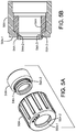
- FIG. 5A is an exploded view of a nut and sleeve of the fitting of FIG. 2 .
- FIG. 5B is a cross-sectional view of the nut and sleeve assembled together.
- FIG. 6 is an isometric view of an alternate embodiment of a non-terminating double containment fitting.
- FIG. 7 is an isometric view of the fitting of FIG. 6 with the nut disengaged.
- FIG. 7A is an isometric view of the fitting of FIG. 6 with the nut and sleeve in exploded view.
- FIG. 8 is a cross-sectional view of the fitting of FIG. 6 .
- FIG. 1 An exemplary operating environment 10 for a non-terminating double containment fitting is illustrated in FIG. 1 .
- a tool 12 uses a fluid, e.g. a liquid chemical in performing some process task at a point of use.
- the point of use may include, for example, a tool used in semiconductor fabrication or pharmaceutical manufacture.
- a container 14 holds a supply of the fluid in its reservoir 16 .
- the fluid is typically a hazardous material. Examples of the hazardous materials include caustic fluids, such as nitric acid, hydrochloric acid, sulfuric acid, hydroxides, ammonia and other chemical formulations.
- the container 14 is connected to the point of use 12 by a double containment tubing system 20 , which includes a primary process tube 22 and an outer, secondary tube 24 .
- the tubes may be of various diameters, depending on the application.
- tube sizes of 1 ⁇ 4-1 ⁇ 2 inch, 3 ⁇ 8-3 ⁇ 4 inch, 1 ⁇ 2-3 ⁇ 4 inch, 1 ⁇ 2-1 inch, 3 ⁇ 4-1 inch, and 1-1-1 ⁇ 4 inch are outer diameter pair sizes for the primary process line or tube and the secondary containment line or tube. Other sizes may be used, depending on the application.
- the primary and secondary lines may be flexible tubing, for example, tubing fabricated of PerFluoroAlkoxy (PFA) and TetraFluorEthylene-Perfluorpropylene (FEP).
- PFA PerFluoroAlkoxy
- FEP TetraFluorEthylene-Perfluorpropylene
- a pump 18 is typically mounted in the container 14 to pump the fluid from the container 14 through the tubing system 20 to the point of use 12 .
- the double containment system 20 addresses the possible situation in which the fluid leaks from the primary tube 22 , with the outer tube containing the leaking fluid and preventing the fluid from leaking outside the system 20 .
- the system 20 is connected to the point of use 12 by a terminating double containment fitting 30 or a non-terminating fitting 100 .
- a terminating double containment fitting is a fitting which passes the primary tube through to an operating fitting or port at the point of use, while terminating or closing the space between the primary and secondary tubes.
- the fitting may be a non-terminating fitting 100 , which passes both the primary and secondary tubes through the fitting. An exemplary embodiment of fitting 100 is described below with respect to FIGS. 6-8 .
- the system 20 is connected to the container 14 by a non-terminating double containment fitting 100 .
- the fitting may be supported by a wall or bulkhead of the container 14 .
- the system 20 is passed through the fitting 100 to the interior of the container, to a bypass non-terminating fitting 50 , and the primary tubing 22 is connected to the pump 18 .
- the fitting 50 within the container 14 may be eliminated.
- a fitting 50 may also optionally be employed at the point of use 12 , as diagrammatically illustrated in FIG. 1 , in phantom.
- the fitting 50 provides a liquid path for liquid leaked from the primary tube 22 and captured within the annular space between the primary and secondary tubes 22 , 24 to be passed out of the system 20 , e.g. back to the container reservoir 14 or to another container or disposition.
- An exemplary embodiment of the fitting 50 is illustrated in FIGS. 2, 3, 3A, 4, 5, 5A and 5B .
- the fitting 50 is a generally T-shaped assembly.
- a fitting body 52 is formed as a unitary one-piece structure, typically by injection-molding, fabricated from PFA in this exemplary embodiment.
- the body 52 defines a central passageway 60 and a bypass passageway 62 perpendicular to the central passageway ( FIG. 4 ).
- the body 52 has a center portion 52 A, disposed between opposed first and second body ports 52 B and 52 C.
- the tubing system 20 from the tool enters the fitting through port 52 B, and the primary tubing 22 is passed through the fitting and out the port 52 C.
- the secondary tubing 24 is terminated in the first body port 52 B at shoulder surface 56 B 1 A ( FIGS. 3A, 4 ).
- a connection system is provided for each of the first and second ports to secure the outer tubing 24 at the fitting port 52 B.
- the first body port 52 B includes a threaded portion 52 B 1 , which is engaged by a nut 56 A.
- the port 52 B further includes a shoulder portion 52 B 2 and a tapered portion 52 B 3 , which terminates at a distal end 52 B 4 , having a beveled tip surface 52 B 4 - 1 ( FIG. 4 ).
- a separate sleeve structure 54 A is fitted within the nut 56 A.
- the sleeve 54 A has a solid configuration, and is free of longitudinal slots.
- the sleeve 54 A has an inner diameter at its interior end which is slightly larger than the outer diameter of the tip 52 B 4 of the tapered portion 52 B 3 , but which is slightly smaller than the outer diameter of the tapered portion 52 B 3 adjacent the shoulder portion 52 B 2 .
- the nut 56 A is fabricated from Polyvinylidene Fluoride (PVDF), and the sleeve 54 A is fabricated from PFA, in this example.
- the opening diameter of the tapered portion 52 B 3 is selected to be slightly larger than the outer diameter of the secondary tubing 24 , so that the tubing system 20 can be inserted through the tapered portion and into the body 52 , with the nut 56 A and sleeve 54 A in an unthreaded, untightened position relative to the fitting body.
- the end of secondary tubing 24 is positioned against the stop shoulder 52 B 1 A of the first body port, i. e. terminated against, shoulder 52 B 1 A.
- FIGS. 5A and 5B illustrate an exemplary nut and sleeve, nut 56 A and sleeve 54 A.
- the sleeve and nut are each of a unitary, one-piece construction in this exemplary embodiment.
- the sleeve is structured for an interference fit into the nut, as illustrated in FIG. 5B .
- the outer diameter of the end 54 A- 1 of the sleeve is slightly larger than the inner diameter of the nut opening at the nut end 56 A- 1 , and the rounded edge of the end 54 A- 1 facilitates the press fit of the sleeve into engagement with the nut.
- the sleeve is formed with a groove 54 A- 2 in which inner lip portion 56 A- 2 is seated in the engaged position.
- the sleeve may be assembled to the nut at the factory, to the assembled condition illustrated in FIG. 5B .
- the sleeve 54 A is fabricated of a softer, more flexible material (such as PFA) than that of the nut (which may be PVDF), facilitating the assembly of the sleeve into the nut.
- the nut 56 A is tightened on the threaded portion 52 B 1 of the fitting body 52 , to the position illustrated in FIG. 3A , drawing the sleeve 54 A along the outer surface of the tapered portion 52 B 3 until stopped against shoulder portion 52 B 2 , and compressing the tapered portion 52 B 3 into contact with the outer surface of the secondary tubing 24 .
- the sleeve 54 A has an internal angled shoulder surface which stops against the corresponding beveled tip surface (surface 52 B 4 - 1 , FIG. 4 ).
- the outer diameter (OD) of the primary tubing 22 is 0.50 inch
- the inner diameter (ID) of the tubing 22 is 0.38 inch
- with corresponding dimensions of the secondary tubing 24 as 0.75 inch OD and 0.63 inch ID. This provides a difference of 0.13 inch between the OD and ID of the primary and second tubings 22 , 24 .
- the threaded portion 52 B 1 , tapered portion 52 B 3 , sleeve 54 A and nut 56 A cooperate to form an annular mechanical smear seal or smear connection of the fitting body 52 to the secondary tubing 24 at the first port 52 B, in the annular region underlying the tapered portion 52 B 3 of the fitting body.
- the smear seal mechanically secures the outer tubing 24 in place within the fitting body, to prevent the tubing from being pulled out of the fitting or pushed through the fitting, while the nut is in place.
- the smear seal extends along a substantial length of the tapered portion, e.g.
- a smear seal or smear connection occurs when similar materials are under a compression force from a harder, more rigid material.
- the nut 56 A is formed of a harder, more rigid material than that of the sleeve 54 A, the fitting body 52 and the outer tubing 24 .
- the sleeve compresses the tapered portion 52 B 3 , in turn compressing the fitting body onto the outer tubing 24 , resulting in a smear seal between the tubing and the fitting body.
- the smear seal contrasts with a conventional compression seal, which typically results in a compression at an annular bead, with a relatively short longitudinal seal length.
- the conventional compression seal also tends to deform the sealed components, typically permanently, at the seal junction.
- the nut 56 A and sleeve 54 A can be removed from the fitting body, to permit disassembly of the fitting from the tubing system 20 , without permanently deforming the tubing 24 .
- the primary tubing 22 is passed through the fitting 50 , extending from the second body port 52 C, and in this exemplary embodiment, is connected to a pump in the supply container 14 .
- the second body port 52 C includes a threaded portion 52 C 1 , which is engaged by a nut 56 B.
- the port 52 C further includes a shoulder portion 52 C 2 , and tapered portion 52 C 3 , which terminates at a distal end 52 C 4 .
- a separate sleeve 54 B is fitted within the nut 56 B.
- the nut 56 B is fabricated of PVDF, and the sleeve 54 B from PFA, in this example.
- the sleeve 54 B, nut 56 B and the tapered portion 52 C 3 of the fitting body 52 cooperate in the same manner as described above regarding the first port.
- the opening diameter of the tapered portion 52 C 3 is selected to be slightly larger than the outer diameter of the primary tubing 22 , so that the tubing 22 can be inserted through the tapered portion and out the body 52 .
- the nut 56 B is tightened on the threaded portion 52 C 1 , to the position illustrated in FIG. 3A , drawing the sleeve 54 B along the outer surface of the tapered portion until stopped at shoulder portion 52 C 2 , and compressing the tapered portion into sealing contact with the outer surface of the primary tubing 22 .
- the threaded portion 52 C 1 , tapered portion 52 C 3 , sleeve 54 B and nut 56 B cooperate to form a mechanical smear seal or smear connection between the tapered portion 52 C 3 of the fitting body and the primary tubing 22 at the second port 52 B.
- the nut 56 B with sleeve 54 B can be removed, to permit disassembly of the fitting from the tubing system 20 .
- the tubing system 20 provides an annular space 26 between the primary tubing 22 and the outer, secondary tubing 24 . Even though the secondary tubing 24 is terminated at shoulder 52 B 2 , the fitting 50 maintains an annular space 26 A ( FIG. 3A ) through the center fitting portion 52 A between the primary tubing 22 and the cylindrical surface 52 A 1 of the portion 52 . Thus, any fluid leaking from the primary tubing 22 in the system 20 may flow into the annular space 26 A.
- the threaded portion 52 C 1 of the second port 52 C includes an internal tapered surface 52 C 1 -A which at its junction with the tapered portion 52 C 4 closes the annular space 26 A. Thus, any fluid in the annular space 26 A cannot escape through the port 52 C.
- a bypass port 52 D is provided, which is in fluid communication with the annular space 26 A, and allows fluid in the annular space to flow out through the port 52 D.
- the bypass port includes a threaded portion 52 D 1 , which is engaged by a nut 56 C.
- the port 52 D further includes a tube engaging portion 52 D 2 , which terminates at a beveled distal end 52 D 3 .
- a bypass passageway 62 is defined through the port 52 D, in communication with the annular spaced 26 A when the tubing 22 is in place within the fitting 50 .
- the nut 56 C is fabricated of PVDF, in this example.
- a flared end 60 A of an overflow tube 60 is fitted over the tube engaging portion 52 D 2 .
- the nut 56 C is tightened on the threaded portion 52 D 1 , to the position illustrated in FIG. 3A , compressing the flared end portion 60 A between the tube engaging portion 52 D 3 and the nut, to provide a leak proof seal.
- the overflow tubing 60 may be connected to the reservoir 16 to replenish the volume of source fluid. Alternatively, the overflow tubing may be connected to a separate overflow container, or to another destination.
- FIGS. 6-8 An alternate embodiment of a non-terminating double containment fitting 100 is illustrated in FIGS. 6-8 .
- both the primary tubing 22 and the secondary tubing 24 are passed through the fitting.
- the secondary tubing may terminate between the fitting and the pump, for example.
- This fitting can be used in applications in which the leaked fluid in the annular space 26 can drain back into the supply container 14 , for example, by cutting or ending the secondary tubing 24 upstream of the pump.
- the fitting 100 includes a fitting body structure 102 having an opening 102 D defined through the body, a threaded nut 104 and sleeve 104 .
- a fitting 50 can be used with the fitting 100 , e.g. at the point of use as illustrated in phantom in FIG. 1 .
- a center portion 102 A of the body structure defines a flange.
- a first threaded end body portion 102 B extends from one side 102 A 1 of the flange or center portion, and is configured to receive the double containment system 20 from the tool.
- the body portion 102 further defines a second threaded end body portion 102 C extending from an opposite side 102 A 2 of the flange portion.
- the body portion 102 C includes an externally threaded portion 102 C 1 , configured for engagement with the internal threads of the nut 104 .
- the body portion 102 C further includes a shoulder portion 102 C 2 and a tapered portion 102 C 3 with tip 102 C 4 , extending away from the flange portion 102 C 1 .
- the opening 102 D in the body structure 102 has a first diameter D 1 in the first threaded end portion 102 B and in the center, flange portion 102 A, which is larger (by 0.13 inch in an exemplary embodiment with the foregoing exemplary dimensions of the primary and secondary tubings) than the outer dimension of the secondary tubing 24 , so that the secondary tubing, with primary tubing 22 , can be easily fitted into the first end portion.
- the surface 102 C 1 -A of the center opening 102 D tapers down to a reduced opening diameter D 2 within portion 102 C 1 of the second portion 102 C.
- Diameter D 2 is just slightly larger than the outer diameter of secondary tubing 24 , so that the tubing 24 can be fitted through the end portion 102 C.
- Exemplary dimensions for D 1 , D 2 are 0.88 inch and 0.76 inch, respectively, for the example of the secondary tubing OD of 0.75 inch
- the sleeve 104 , nut 106 and the tapered portion 102 C 3 with tip 102 C 4 are cooperatively dimensioned so that, as the nut 106 is tightened on the threaded portion 102 C 1 , to the position illustrated in FIG. 8 , drawing the sleeve 104 along the outer surface of the tapered portion until stopped at shoulder portion 102 C 2 , and compressing the tapered portion into frictional contact with the outer surface of the primary tubing 22 , forming a mechanical smear seal, or smear connection, in the same manner as described above with respect to nut 56 A, sleeve 54 A, tapered portion 52 B 3 and tubing 24 .
- the nut 106 with sleeve 104 can be removed from the fitting body 102 to allow the tubing system to be withdrawn from the fitting, or repositioned along its longitudinal length
- the fitting 100 may be secured in a bulkhead opening, with a nut (not shown in FIG. 8 ) threaded onto the threaded portion 102 B 1 to sandwich the bulkhead between the flange surface 102 A 1 and the nut.
Landscapes
- Engineering & Computer Science (AREA)
- General Engineering & Computer Science (AREA)
- Mechanical Engineering (AREA)
- Joints With Pressure Members (AREA)
- Pipe Accessories (AREA)
Abstract
Description
Claims (17)
Priority Applications (1)
| Application Number | Priority Date | Filing Date | Title |
|---|---|---|---|
| US16/539,841 US10746337B2 (en) | 2015-11-04 | 2019-08-13 | Non-terminating double containment fitting |
Applications Claiming Priority (2)
| Application Number | Priority Date | Filing Date | Title |
|---|---|---|---|
| US14/932,879 US10386002B2 (en) | 2015-11-04 | 2015-11-04 | Non-terminating double containment fitting |
| US16/539,841 US10746337B2 (en) | 2015-11-04 | 2019-08-13 | Non-terminating double containment fitting |
Related Parent Applications (1)
| Application Number | Title | Priority Date | Filing Date |
|---|---|---|---|
| US14/932,879 Division US10386002B2 (en) | 2015-11-04 | 2015-11-04 | Non-terminating double containment fitting |
Publications (2)
| Publication Number | Publication Date |
|---|---|
| US20190368644A1 US20190368644A1 (en) | 2019-12-05 |
| US10746337B2 true US10746337B2 (en) | 2020-08-18 |
Family
ID=58635291
Family Applications (2)
| Application Number | Title | Priority Date | Filing Date |
|---|---|---|---|
| US14/932,879 Active 2038-04-29 US10386002B2 (en) | 2015-11-04 | 2015-11-04 | Non-terminating double containment fitting |
| US16/539,841 Active US10746337B2 (en) | 2015-11-04 | 2019-08-13 | Non-terminating double containment fitting |
Family Applications Before (1)
| Application Number | Title | Priority Date | Filing Date |
|---|---|---|---|
| US14/932,879 Active 2038-04-29 US10386002B2 (en) | 2015-11-04 | 2015-11-04 | Non-terminating double containment fitting |
Country Status (4)
| Country | Link |
|---|---|
| US (2) | US10386002B2 (en) |
| KR (1) | KR102199946B1 (en) |
| CN (1) | CN106641538B (en) |
| TW (1) | TWI698610B (en) |
Families Citing this family (8)
| Publication number | Priority date | Publication date | Assignee | Title |
|---|---|---|---|---|
| KR101979303B1 (en) * | 2017-11-29 | 2019-05-15 | 승진산업 (주) | Piping module |
| CN111527338A (en) * | 2017-12-20 | 2020-08-11 | 美国圣戈班性能塑料公司 | Double Hermetic Joints and Double Hermetic Joint Assemblies |
| US10962153B2 (en) * | 2018-07-24 | 2021-03-30 | Reliance Worldwide Corporation | Terminal component for plumbing configuration |
| CN108825910B (en) * | 2018-08-24 | 2024-04-05 | 日丰企业(佛山)有限公司 | Capillary tube water diversion joint |
| US11518114B2 (en) * | 2019-06-07 | 2022-12-06 | Fit-Line, Inc. | Method and apparatus to assemble a high purity liquid distribution system |
| JP7424722B2 (en) * | 2019-08-09 | 2024-01-30 | 三桜工業株式会社 | Piping branch structure |
| JP7344766B2 (en) * | 2019-11-15 | 2023-09-14 | 日本ピラー工業株式会社 | pipe fittings |
| US12248344B2 (en) * | 2021-03-26 | 2025-03-11 | Intel Corporation | Technologies for liquid cooling interfaces |
Family Cites Families (13)
| Publication number | Priority date | Publication date | Assignee | Title |
|---|---|---|---|---|
| DE4106378A1 (en) * | 1991-02-28 | 1992-09-10 | Hewing Gmbh | CONNECTING DEVICE FOR PLASTIC PIPES AND METHOD FOR CONNECTING A PLASTIC PIPE |
| US5213375A (en) * | 1991-12-24 | 1993-05-25 | Wu Huang H | Quick pipe connector |
| US5398976A (en) * | 1992-08-03 | 1995-03-21 | Environ Products, Inc. | Connecting device for pipe assemblies |
| US5498036A (en) | 1994-09-09 | 1996-03-12 | Furon Company | Dual containment fitting |
| US5687993A (en) | 1994-10-31 | 1997-11-18 | Hyclone Laboratories | Dual containment system for transferring sterile fluids to and from a container |
| FR2760064B1 (en) | 1997-02-25 | 2002-10-25 | Fluoroware Inc | THREADED CONNECTION AND DOUBLE CONTAINMENT SYSTEM |
| US20100133812A1 (en) * | 2005-06-27 | 2010-06-03 | Swagelok Company | Tube Fitting |
| GB2439148A (en) * | 2006-06-16 | 2007-12-19 | Wellstream Int Ltd | Pipe armour wires support in terminating collar |
| US20090284004A1 (en) | 2008-05-15 | 2009-11-19 | Simmons Tom M | Double containment system, fittings for fluid flow components and associated methods |
| CN202812536U (en) * | 2012-09-11 | 2013-03-20 | 冠礼控制科技(上海)有限公司 | Pipe joint connector of chemicals supply system |
| CN106715992B (en) * | 2014-08-26 | 2020-11-03 | 恩特格里斯公司 | High Torque Polymer Fittings |
| CN204692920U (en) * | 2015-05-14 | 2015-10-07 | 泛泰大西(常州)电子科技有限公司 | Cold insulated cabinet positioning base |
| JP6581837B2 (en) * | 2015-08-04 | 2019-09-25 | 高砂熱学工業株式会社 | Double tube liquid leakage prevention structure and construction method |
-
2015
- 2015-11-04 US US14/932,879 patent/US10386002B2/en active Active
-
2016
- 2016-10-21 TW TW105134013A patent/TWI698610B/en active
- 2016-11-01 KR KR1020160144140A patent/KR102199946B1/en active Active
- 2016-11-03 CN CN201610956240.8A patent/CN106641538B/en active Active
-
2019
- 2019-08-13 US US16/539,841 patent/US10746337B2/en active Active
Also Published As
| Publication number | Publication date |
|---|---|
| KR20170052486A (en) | 2017-05-12 |
| CN106641538B (en) | 2021-01-01 |
| TWI698610B (en) | 2020-07-11 |
| TW201727126A (en) | 2017-08-01 |
| KR102199946B1 (en) | 2021-01-08 |
| US20170122473A1 (en) | 2017-05-04 |
| CN106641538A (en) | 2017-05-10 |
| US20190368644A1 (en) | 2019-12-05 |
| US10386002B2 (en) | 2019-08-20 |
Similar Documents
| Publication | Publication Date | Title |
|---|---|---|
| US10746337B2 (en) | Non-terminating double containment fitting | |
| CN105121931B (en) | Accessory for pipe closed system | |
| CN105190148B (en) | Pipe connection | |
| US9279526B2 (en) | Apparatuses and methods for providing finger-tightened and ratchet-secured connections between conduits | |
| US10682506B2 (en) | Connecting structure for medical use | |
| US20110227337A1 (en) | Fitting for jacketed tubing | |
| US5775743A (en) | Nut and split ring assembly | |
| CN121497903A (en) | Double-sealed joints and double-sealed joint assemblies | |
| KR19990024027A (en) | Adjustable Leak-proof Fastening System | |
| US10571060B2 (en) | Structure of resin-made pipe joint | |
| EP3508769A1 (en) | Pipe joint and engagement member | |
| US20110198843A1 (en) | Port structure and fluid device including the port structure | |
| US20090284004A1 (en) | Double containment system, fittings for fluid flow components and associated methods | |
| CN101802475A (en) | Fittings for Tube Containment Systems | |
| CN110573783A (en) | Connection structure of fluid equipment | |
| JP2006064080A (en) | Connection structure for fluid apparatuses | |
| US8672365B2 (en) | Quick connect coupling having inverted guide and sealing zones | |
| US12158223B2 (en) | Conversion adapter and fitting with the same | |
| US10883633B2 (en) | Zero dead volume fitting assembly | |
| JP4741575B2 (en) | Fluid control device for high pressure analytical instruments | |
| JP4324576B2 (en) | Connection structure between fluid devices | |
| CN110657307A (en) | Snap Rings, Connecting Assemblies, Snap Assemblies and Connecting Fittings | |
| JP4848467B2 (en) | Connection structure between flange piping and fluid equipment | |
| KR101638835B1 (en) | Pipe connector | |
| JP2006161830A (en) | Connection structure between flange piping and connection structure between flange piping and fluid equipment |
Legal Events
| Date | Code | Title | Description |
|---|---|---|---|
| AS | Assignment |
Owner name: FIT-LINE, INC, CALIFORNIA Free format text: ASSIGNMENT OF ASSIGNORS INTEREST;ASSIGNOR:HAYES, FRANK F., JR.;REEL/FRAME:050042/0536 Effective date: 20151103 |
|
| FEPP | Fee payment procedure |
Free format text: ENTITY STATUS SET TO UNDISCOUNTED (ORIGINAL EVENT CODE: BIG.); ENTITY STATUS OF PATENT OWNER: SMALL ENTITY |
|
| FEPP | Fee payment procedure |
Free format text: ENTITY STATUS SET TO SMALL (ORIGINAL EVENT CODE: SMAL); ENTITY STATUS OF PATENT OWNER: SMALL ENTITY |
|
| STPP | Information on status: patent application and granting procedure in general |
Free format text: DOCKETED NEW CASE - READY FOR EXAMINATION |
|
| STPP | Information on status: patent application and granting procedure in general |
Free format text: NON FINAL ACTION MAILED |
|
| STPP | Information on status: patent application and granting procedure in general |
Free format text: NOTICE OF ALLOWANCE MAILED -- APPLICATION RECEIVED IN OFFICE OF PUBLICATIONS |
|
| STPP | Information on status: patent application and granting procedure in general |
Free format text: PUBLICATIONS -- ISSUE FEE PAYMENT VERIFIED |
|
| STCF | Information on status: patent grant |
Free format text: PATENTED CASE |
|
| MAFP | Maintenance fee payment |
Free format text: PAYMENT OF MAINTENANCE FEE, 4TH YR, SMALL ENTITY (ORIGINAL EVENT CODE: M2551); ENTITY STATUS OF PATENT OWNER: SMALL ENTITY Year of fee payment: 4 |