US10745256B2 - Dual-screw line guide - Google Patents
Dual-screw line guide Download PDFInfo
- Publication number
- US10745256B2 US10745256B2 US16/034,345 US201816034345A US10745256B2 US 10745256 B2 US10745256 B2 US 10745256B2 US 201816034345 A US201816034345 A US 201816034345A US 10745256 B2 US10745256 B2 US 10745256B2
- Authority
- US
- United States
- Prior art keywords
- screw
- line
- helical groove
- groove
- counter
- Prior art date
- Legal status (The legal status is an assumption and is not a legal conclusion. Google has not performed a legal analysis and makes no representation as to the accuracy of the status listed.)
- Expired - Fee Related, expires
Links
- UQZIWOQVLUASCR-UHFFFAOYSA-N alumane;titanium Chemical compound [AlH3].[Ti] UQZIWOQVLUASCR-UHFFFAOYSA-N 0.000 claims description 4
- VYZAMTAEIAYCRO-UHFFFAOYSA-N Chromium Chemical compound [Cr] VYZAMTAEIAYCRO-UHFFFAOYSA-N 0.000 claims description 2
- RTAQQCXQSZGOHL-UHFFFAOYSA-N Titanium Chemical compound [Ti] RTAQQCXQSZGOHL-UHFFFAOYSA-N 0.000 claims description 2
- NRTOMJZYCJJWKI-UHFFFAOYSA-N Titanium nitride Chemical compound [Ti]#N NRTOMJZYCJJWKI-UHFFFAOYSA-N 0.000 claims description 2
- -1 chrome nitride Chemical class 0.000 claims description 2
- 238000000576 coating method Methods 0.000 claims description 2
- 229910052719 titanium Inorganic materials 0.000 claims description 2
- 239000010936 titanium Substances 0.000 claims description 2
- ZVWKZXLXHLZXLS-UHFFFAOYSA-N zirconium nitride Chemical compound [Zr]#N ZVWKZXLXHLZXLS-UHFFFAOYSA-N 0.000 claims description 2
- 230000009977 dual effect Effects 0.000 description 16
- 230000002457 bidirectional effect Effects 0.000 description 4
- 238000004804 winding Methods 0.000 description 3
- 238000000034 method Methods 0.000 description 2
- 229910000831 Steel Inorganic materials 0.000 description 1
- 239000006260 foam Substances 0.000 description 1
- 229910052751 metal Inorganic materials 0.000 description 1
- 239000002184 metal Substances 0.000 description 1
- 239000000203 mixture Substances 0.000 description 1
- 238000012986 modification Methods 0.000 description 1
- 230000004048 modification Effects 0.000 description 1
- 230000003287 optical effect Effects 0.000 description 1
- 239000004033 plastic Substances 0.000 description 1
- 239000005060 rubber Substances 0.000 description 1
- 229910001220 stainless steel Inorganic materials 0.000 description 1
- 239000010935 stainless steel Substances 0.000 description 1
- 239000010959 steel Substances 0.000 description 1
Images


Classifications
-
- B—PERFORMING OPERATIONS; TRANSPORTING
- B66—HOISTING; LIFTING; HAULING
- B66D—CAPSTANS; WINCHES; TACKLES, e.g. PULLEY BLOCKS; HOISTS
- B66D1/00—Rope, cable, or chain winding mechanisms; Capstans
- B66D1/28—Other constructional details
- B66D1/36—Guiding, or otherwise ensuring winding in an orderly manner, of ropes, cables, or chains
-
- B—PERFORMING OPERATIONS; TRANSPORTING
- B65—CONVEYING; PACKING; STORING; HANDLING THIN OR FILAMENTARY MATERIAL
- B65H—HANDLING THIN OR FILAMENTARY MATERIAL, e.g. SHEETS, WEBS, CABLES
- B65H57/00—Guides for filamentary materials; Supports therefor
- B65H57/04—Guiding surfaces within slots or grooves
-
- B—PERFORMING OPERATIONS; TRANSPORTING
- B65—CONVEYING; PACKING; STORING; HANDLING THIN OR FILAMENTARY MATERIAL
- B65H—HANDLING THIN OR FILAMENTARY MATERIAL, e.g. SHEETS, WEBS, CABLES
- B65H59/00—Adjusting or controlling tension in filamentary material, e.g. for preventing snarling; Applications of tension indicators
- B65H59/40—Applications of tension indicators
Definitions
- the invention described herein relates generally to spooling.
- Line guides capable of keeping a line on track when winding or unwinding the line require the ability to handle forces in multiple directions.
- the human hand is used to guide lines due to the expense and complexity of a line guide as well as due to the human capacity to handle changes in force and direction quickly.
- the line guide may experience forces in lateral directions. For example, a winch mounted facing one direction may be pulling on an object to the side of the face of the winch. The force may be partially compensated for by a fairlead, but when the forces become too high laterally, the line guide can be broken.
- the disclosure provides an apparatus with a first screw and a second screw mounted adjacent and parallel to each other.
- the first screw has a first helical groove.
- the second screw has a second helical groove.
- the first helical groove and the second helical groove align, thereby forming a groove space, as the first screw and the second screw rotate in opposing radial directions.
- the groove space is configured for a line to pass therethrough.
- the first screw also has a first counter-helical groove that is counter-rotating to the first helical groove.
- the second screw has a second counter-helical groove that is counter-rotating to the second helical groove.
- the first counter-helical groove and the second counter-helical groove align as the first screw and the second screw rotate.
- the groove space consists of a first groove space and a second groove space.
- the first groove space is defined by the first helical groove and the second helical groove.
- the second groove space is defined by the first counter-helical groove and the second counter-helical groove.
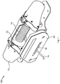
- FIG. 1 is a front-right top isometric view of a winch with a dual screw.
- FIG. 2 is a front elevation view of the winch and dual screw of FIG. 1 .
- FIG. 3 is a front-right top isometric view of the winch and dual screw of FIG. 1 with an outer shell removed from the front of the dual screw.
- FIG. 4 is a rear-left top isometric view of the dual screw separated from the winch of FIG. 1 .
- FIG. 5 is a rear elevation view of the dual screw of FIG. 4 with a portion of the casing around the gearing of the dual screw removed.
- FIG. 6 is a front elevation close-up view of the dual screws of FIG. 4 .
- spooling device is meant to refer to a device that winds such as a spooler, winch, winder, and coilers.
- line is meant to refer to cable, wire, line, cord, twine, strand, or rope.
- Line guides capable of keeping a line on track when winding or unwinding the line, require the ability to handle forces in multiple directions.
- the human hand is used to guide lines due to the human capacity to handle changes in force and direction quickly.
- the line guide may experience forces in lateral directions that are not compensated for by a fairlead, which can break the line guide.
- a line guide that can be used both with and without lateral loads is disclosed herein.
- the line guide consists of two bidirectional screws with grooves that align to leave a space between the screws. The line is passed through the space between the grooves. As the screws rotate, the line is moved laterally. Not only does this arrangement overcome the issue of lateral forces from the line, but has many benefits, some of which are presented herein.
- FIG. 1 is a front-right top isometric view 100 of a winch with a dual screw that may be used with the devices disclosed herein.
- FIG. 2 is a front elevation view 200 of the winch and dual screw of FIG. 1 .
- FIG. 3 is a front-right top isometric view 300 of the winch and dual screw of FIG. 1 with an outer shell removed from the front of the dual screw.
- FIG. 4 is a rear-left top isometric view 400 of the dual screw separated from the winch of FIG. 1 .
- FIG. 5 is a rear elevation view 500 of the dual screw of FIG. 4 with a back portion of the casing around the gearing of the dual screw removed.
- FIG. 6 is a front elevation close-up view 600 of the dual screws of FIG. 4 .
- a winch 10 includes a spool 12 on which a line 14 is spooled and unspooled.
- a top screw 18 and a bottom screw 16 are mounted to a casing 22 which is mounted on the winch 10 inside of an outer shell 20 .
- the top screw 18 and the bottom screw 16 are rotated counter to each other by turning shaft 24 , thereby rotating the top screw 18 one direction while gearing 28 of gear assembly 26 causes the bottom screw 16 to rotate the opposite direction.
- the top screw 18 and the bottom screw 16 are thereby mounted adjacent and parallel to each other and rotate in opposing radial directions.
- the bottom screw 16 is a bidirectional helical screw with a first helical groove 30 and a first counter-helical groove 32 .
- the top screw 18 is a bidirectional helical screw with a second helical groove 34 and a second counter-helical groove 36 .
- the first helical groove 30 and the second helical groove 34 align as the top screw 18 and the bottom screw 16 rotate in opposing radial directions.
- the first counter-helical groove 32 and the second counter-helical groove 36 also align as the top screw 18 and the bottom screw 16 rotate in opposing radial directions.
- This alignment of grooves results in a groove space 15 .
- the groove space 15 occurs in 7 locations. In other embodiments, the number of occurrences may be greater or fewer, depending on screw length and groove width.
- the line 14 passes through the groove space 15 .
- the groove space 15 continually shifts, thus moving the line 14 laterally back and forth across the screw 16 and 18 .
- the bidirectional nature of the screws 16 and 18 causes the line 14 to switch direction of travel.
- the groove space 15 containing the line 14 is aligned with whatever point on the spool at which the line 14 is spooling or unspooling.
- the line 14 is withdrawn from the spool 12 by rotation of the top screw 18 in one direction (and the opposite direction by the bottom screw 16 ) and is spooled onto the spool 12 by rotation of the top screw 18 in the opposite direction (and the first direction by the bottom screw 16 ).
- the line 14 has a diameter at least as large as the groove space 15 .
- a member 38 contains a tensioner that applies a squeezing force that pushes the first screw and the second screw together such that the line 14 is squeezed between the top screw 18 and the bottom screw 16 .
- the line 14 is kept taut while being drawn out of the winch 10 .
- the line is guided by the groove space 15 but is not restricted in returning to the winch 10 by extra pressure on line 14 .
- one or more sensors are used to detect lateral forces applied by the line to the first screw, the second screw, or both.
- these sensors may be optical sensors mounted in member 38 , in gear assembly 26 , or in both.
- the sensors detect the force is over a force threshold, the squeezing force from the tensioner is increased. This prevents the line 14 from being pulled out of the groove space 15 .
- the rotational speeds of the spool 12 and screws 16 and 18 is altered to compensate for the increased squeezing force.
- one or more sensors are used to detect the location of the line 14 between screws 16 and 18 and compare it to the point on the spool where the line 14 is winding or unwinding.
- these sensors may be mounted on the interior of the outer shell 20 and may include laser distance finders or other proximity sensors.
- the tensioner may be released and the screws 16 and 18 may be rotated to bring the line 14 into alignment with the point on the spool.
- rotation of the spool 12 is paused. In other embodiments, rotation of the spool 12 is slowed.
- a single motor with gearing is used for the winch and both screws.
- a first motor is used for the winch and a second motor with gearing is used for the screws.
- the winch and both screws all have independent motors.
- the screws are single directional with only a single groove each, moving the line a single direction.
- the line is a cable, a wire, a line, a cord, twine, a strand, or a rope.
- the line is a cable made of braided metal strands.
- the first screw and the second screw may have rounded crests.
- portions of the screws have ribbed textures to increase grasping ability by the screws.
- the screws are made of steel, stainless steel, foam, rubber, plastic, or a combination thereof. In some embodiments the screws are heat treated, surface hardened, or a combination thereof. In one example, the screws are 1.5′′ in diameter for a 12,000 lbf rated winch with grooves of 3 ⁇ 8′′ diameter for a 3 ⁇ 8′′ diameter line.
- the screws have coatings including titanium nitride, titanium carbo-nitride, titanium aluminum nitride, aluminum titanium nitride, chrome nitride, zirconium nitride, chrome, or a combination thereof.
Landscapes
- Engineering & Computer Science (AREA)
- Mechanical Engineering (AREA)
- Transmission Devices (AREA)
Abstract
Description
Claims (14)
Priority Applications (1)
| Application Number | Priority Date | Filing Date | Title |
|---|---|---|---|
| US16/034,345 US10745256B2 (en) | 2018-07-12 | 2018-07-12 | Dual-screw line guide |
Applications Claiming Priority (1)
| Application Number | Priority Date | Filing Date | Title |
|---|---|---|---|
| US16/034,345 US10745256B2 (en) | 2018-07-12 | 2018-07-12 | Dual-screw line guide |
Publications (2)
| Publication Number | Publication Date |
|---|---|
| US20200017338A1 US20200017338A1 (en) | 2020-01-16 |
| US10745256B2 true US10745256B2 (en) | 2020-08-18 |
Family
ID=69138965
Family Applications (1)
| Application Number | Title | Priority Date | Filing Date |
|---|---|---|---|
| US16/034,345 Expired - Fee Related US10745256B2 (en) | 2018-07-12 | 2018-07-12 | Dual-screw line guide |
Country Status (1)
| Country | Link |
|---|---|
| US (1) | US10745256B2 (en) |
Families Citing this family (4)
| Publication number | Priority date | Publication date | Assignee | Title |
|---|---|---|---|---|
| WO2020172914A1 (en) * | 2019-02-28 | 2020-09-03 | 杭州天铭科技股份有限公司 | Winch, rope guide, and transmission device with clutch function |
| WO2021003225A1 (en) * | 2019-07-03 | 2021-01-07 | Greenlee Tools, Inc. | Cable puller adapter for use with a cable puller and its method of use |
| US11987480B2 (en) * | 2019-10-23 | 2024-05-21 | Kanister Industries Llc | Cable guide device |
| CN117228431A (en) * | 2023-10-25 | 2023-12-15 | 烽火通信科技股份有限公司 | A cable take-up device |
Citations (19)
| Publication number | Priority date | Publication date | Assignee | Title |
|---|---|---|---|---|
| US1472847A (en) * | 1920-01-12 | 1923-11-06 | George J Mcgann | High-speed traverse mechanism for winding machines |
| US1551251A (en) * | 1924-04-24 | 1925-08-25 | Nat Standard Co | Reeling machine |
| US1797331A (en) * | 1929-12-30 | 1931-03-24 | James E Dale | Fair-lead |
| GB380910A (en) * | 1931-08-18 | 1932-09-29 | Ernest Clare | Improvements in laying on or coiling gears for winding drums of winches, cranes and the like |
| US1918587A (en) * | 1930-12-03 | 1933-07-18 | T C Entwistle Company | Traverse-motion for winding machines and the like |
| US2419003A (en) * | 1944-07-24 | 1947-04-15 | Arundel Coulthard & Co Ltd | Yarn winding machine |
| US2519461A (en) * | 1947-02-08 | 1950-08-22 | Western Electric Co | Strand distributing apparatus |
| GB670037A (en) * | 1949-05-06 | 1952-04-09 | Torsten Karlsson | Improved winding device |
| US2757883A (en) * | 1952-11-08 | 1956-08-07 | Firm Schlang & Reichart | Traversing guide for a rope winch |
| US2962906A (en) * | 1958-01-24 | 1960-12-06 | George E Failing Company | Level winding mechanism and adjusting means therefor |
| US3224697A (en) * | 1963-04-03 | 1965-12-21 | Jr Arthur D Struble | Balloon cable reeling device |
| US3266741A (en) * | 1963-04-20 | 1966-08-16 | British Nylon Spinners Ltd | Method and apparatus for winding yarn |
| US3347490A (en) * | 1966-02-16 | 1967-10-17 | Collins Radio Co | Level wind for airborne trailing wire antenna parallel to the drum axis |
| US3456898A (en) * | 1967-03-31 | 1969-07-22 | Jarl H Anderson | Activator for level wire winder |
| US3533575A (en) * | 1968-11-07 | 1970-10-13 | Breeze Corp | Intermittent level wind |
| US3587994A (en) * | 1969-12-29 | 1971-06-28 | Nat Mine Service Co | Spooling device |
| US3937420A (en) * | 1971-10-29 | 1976-02-10 | Galis Alex J | Level wind device |
| US4005834A (en) * | 1974-06-11 | 1977-02-01 | Societe Anonyme Francaise Du Ferodo | Winding cables and the like on to storage drums |
| US20190300344A1 (en) * | 2018-03-30 | 2019-10-03 | Ningbo Lianda Winch Co., Ltd. | Winch for vehicle |
-
2018
- 2018-07-12 US US16/034,345 patent/US10745256B2/en not_active Expired - Fee Related
Patent Citations (19)
| Publication number | Priority date | Publication date | Assignee | Title |
|---|---|---|---|---|
| US1472847A (en) * | 1920-01-12 | 1923-11-06 | George J Mcgann | High-speed traverse mechanism for winding machines |
| US1551251A (en) * | 1924-04-24 | 1925-08-25 | Nat Standard Co | Reeling machine |
| US1797331A (en) * | 1929-12-30 | 1931-03-24 | James E Dale | Fair-lead |
| US1918587A (en) * | 1930-12-03 | 1933-07-18 | T C Entwistle Company | Traverse-motion for winding machines and the like |
| GB380910A (en) * | 1931-08-18 | 1932-09-29 | Ernest Clare | Improvements in laying on or coiling gears for winding drums of winches, cranes and the like |
| US2419003A (en) * | 1944-07-24 | 1947-04-15 | Arundel Coulthard & Co Ltd | Yarn winding machine |
| US2519461A (en) * | 1947-02-08 | 1950-08-22 | Western Electric Co | Strand distributing apparatus |
| GB670037A (en) * | 1949-05-06 | 1952-04-09 | Torsten Karlsson | Improved winding device |
| US2757883A (en) * | 1952-11-08 | 1956-08-07 | Firm Schlang & Reichart | Traversing guide for a rope winch |
| US2962906A (en) * | 1958-01-24 | 1960-12-06 | George E Failing Company | Level winding mechanism and adjusting means therefor |
| US3224697A (en) * | 1963-04-03 | 1965-12-21 | Jr Arthur D Struble | Balloon cable reeling device |
| US3266741A (en) * | 1963-04-20 | 1966-08-16 | British Nylon Spinners Ltd | Method and apparatus for winding yarn |
| US3347490A (en) * | 1966-02-16 | 1967-10-17 | Collins Radio Co | Level wind for airborne trailing wire antenna parallel to the drum axis |
| US3456898A (en) * | 1967-03-31 | 1969-07-22 | Jarl H Anderson | Activator for level wire winder |
| US3533575A (en) * | 1968-11-07 | 1970-10-13 | Breeze Corp | Intermittent level wind |
| US3587994A (en) * | 1969-12-29 | 1971-06-28 | Nat Mine Service Co | Spooling device |
| US3937420A (en) * | 1971-10-29 | 1976-02-10 | Galis Alex J | Level wind device |
| US4005834A (en) * | 1974-06-11 | 1977-02-01 | Societe Anonyme Francaise Du Ferodo | Winding cables and the like on to storage drums |
| US20190300344A1 (en) * | 2018-03-30 | 2019-10-03 | Ningbo Lianda Winch Co., Ltd. | Winch for vehicle |
Also Published As
| Publication number | Publication date |
|---|---|
| US20200017338A1 (en) | 2020-01-16 |
Similar Documents
| Publication | Publication Date | Title |
|---|---|---|
| US10745256B2 (en) | Dual-screw line guide | |
| CN102387979B (en) | Winches and autonomous mobile devices incorporating winches | |
| JP7554858B2 (en) | High-speed reduction belt-driven linear actuator | |
| US9382103B2 (en) | Hoist | |
| CN105143092A (en) | Traction winch | |
| US9988250B2 (en) | Drum for a motorized lifting/pulling device | |
| US10336590B2 (en) | Line traction for a motorized lifting/pulling device | |
| CN101951809A (en) | Furniture drive with a drive unit | |
| US20230166952A1 (en) | Winch with line guide driven by wound line | |
| US20190291156A1 (en) | Coiling head apparatus and system | |
| US10875739B2 (en) | Detachable line guide | |
| US10112809B2 (en) | Reliable spooling for a motorized lifting/pulling device | |
| JPH11194243A (en) | Method and apparatus for manufacturing SZ slot type optical fiber cable | |
| CN111302251A (en) | Winding drum | |
| CN110844712B (en) | A shore power cable management device | |
| US3563481A (en) | Controllably wound cable takeup reel | |
| CN112537693A (en) | Traction incoming line angle reciprocating self-changing type wire-clamping-preventing wire winding device | |
| US10056744B2 (en) | Apparatus for selectively opening up a portion of a cable | |
| CN105752744A (en) | Guide device for copper wire winding drum take-up | |
| EP2980003B1 (en) | Winch with a cable guiding device | |
| WO2012046468A1 (en) | Wire accumulator | |
| CA3073074C (en) | High reduction belt-driven linear actuator | |
| CN210854726U (en) | A winding device for cable production | |
| CN217626904U (en) | Tension adjusting mechanism, unreeling machine and compound traction production line | |
| CN120165328A (en) | Cable pulling device and method for pulling a cable into an empty pipe |
Legal Events
| Date | Code | Title | Description |
|---|---|---|---|
| FEPP | Fee payment procedure |
Free format text: ENTITY STATUS SET TO UNDISCOUNTED (ORIGINAL EVENT CODE: BIG.); ENTITY STATUS OF PATENT OWNER: SMALL ENTITY |
|
| FEPP | Fee payment procedure |
Free format text: ENTITY STATUS SET TO SMALL (ORIGINAL EVENT CODE: SMAL); ENTITY STATUS OF PATENT OWNER: SMALL ENTITY |
|
| STPP | Information on status: patent application and granting procedure in general |
Free format text: NON FINAL ACTION MAILED |
|
| STPP | Information on status: patent application and granting procedure in general |
Free format text: NOTICE OF ALLOWANCE MAILED -- APPLICATION RECEIVED IN OFFICE OF PUBLICATIONS |
|
| ZAAA | Notice of allowance and fees due |
Free format text: ORIGINAL CODE: NOA |
|
| ZAAB | Notice of allowance mailed |
Free format text: ORIGINAL CODE: MN/=. |
|
| STPP | Information on status: patent application and granting procedure in general |
Free format text: AWAITING TC RESP, ISSUE FEE PAYMENT VERIFIED |
|
| ZAAA | Notice of allowance and fees due |
Free format text: ORIGINAL CODE: NOA |
|
| STCF | Information on status: patent grant |
Free format text: PATENTED CASE |
|
| FEPP | Fee payment procedure |
Free format text: MAINTENANCE FEE REMINDER MAILED (ORIGINAL EVENT CODE: REM.); ENTITY STATUS OF PATENT OWNER: SMALL ENTITY |
|
| LAPS | Lapse for failure to pay maintenance fees |
Free format text: PATENT EXPIRED FOR FAILURE TO PAY MAINTENANCE FEES (ORIGINAL EVENT CODE: EXP.); ENTITY STATUS OF PATENT OWNER: SMALL ENTITY |
|
| STCH | Information on status: patent discontinuation |
Free format text: PATENT EXPIRED DUE TO NONPAYMENT OF MAINTENANCE FEES UNDER 37 CFR 1.362 |
|
| FP | Lapsed due to failure to pay maintenance fee |
Effective date: 20240818 |