US10732872B2 - Storage system and storage control method - Google Patents
Storage system and storage control method Download PDFInfo
- Publication number
- US10732872B2 US10732872B2 US16/329,570 US201716329570A US10732872B2 US 10732872 B2 US10732872 B2 US 10732872B2 US 201716329570 A US201716329570 A US 201716329570A US 10732872 B2 US10732872 B2 US 10732872B2
- Authority
- US
- United States
- Prior art keywords
- data transfer
- storage devices
- switches
- path
- storage
- Prior art date
- Legal status (The legal status is an assumption and is not a legal conclusion. Google has not performed a legal analysis and makes no representation as to the accuracy of the status listed.)
- Active
Links
Images


Classifications
-
- G—PHYSICS
- G06—COMPUTING OR CALCULATING; COUNTING
- G06F—ELECTRIC DIGITAL DATA PROCESSING
- G06F13/00—Interconnection of, or transfer of information or other signals between, memories, input/output devices or central processing units
- G06F13/38—Information transfer, e.g. on bus
- G06F13/42—Bus transfer protocol, e.g. handshake; Synchronisation
- G06F13/4282—Bus transfer protocol, e.g. handshake; Synchronisation on a serial bus, e.g. I2C bus, SPI bus
-
- G—PHYSICS
- G06—COMPUTING OR CALCULATING; COUNTING
- G06F—ELECTRIC DIGITAL DATA PROCESSING
- G06F13/00—Interconnection of, or transfer of information or other signals between, memories, input/output devices or central processing units
- G06F13/14—Handling requests for interconnection or transfer
-
- G—PHYSICS
- G06—COMPUTING OR CALCULATING; COUNTING
- G06F—ELECTRIC DIGITAL DATA PROCESSING
- G06F13/00—Interconnection of, or transfer of information or other signals between, memories, input/output devices or central processing units
- G06F13/38—Information transfer, e.g. on bus
-
- G—PHYSICS
- G06—COMPUTING OR CALCULATING; COUNTING
- G06F—ELECTRIC DIGITAL DATA PROCESSING
- G06F13/00—Interconnection of, or transfer of information or other signals between, memories, input/output devices or central processing units
- G06F13/38—Information transfer, e.g. on bus
- G06F13/40—Bus structure
- G06F13/4004—Coupling between buses
- G06F13/4022—Coupling between buses using switching circuits, e.g. switching matrix, connection or expansion network
-
- G—PHYSICS
- G06—COMPUTING OR CALCULATING; COUNTING
- G06F—ELECTRIC DIGITAL DATA PROCESSING
- G06F3/00—Input arrangements for transferring data to be processed into a form capable of being handled by the computer; Output arrangements for transferring data from processing unit to output unit, e.g. interface arrangements
- G06F3/06—Digital input from, or digital output to, record carriers, e.g. RAID, emulated record carriers or networked record carriers
- G06F3/0601—Interfaces specially adapted for storage systems
- G06F3/0602—Interfaces specially adapted for storage systems specifically adapted to achieve a particular effect
- G06F3/061—Improving I/O performance
- G06F3/0611—Improving I/O performance in relation to response time
-
- G—PHYSICS
- G06—COMPUTING OR CALCULATING; COUNTING
- G06F—ELECTRIC DIGITAL DATA PROCESSING
- G06F3/00—Input arrangements for transferring data to be processed into a form capable of being handled by the computer; Output arrangements for transferring data from processing unit to output unit, e.g. interface arrangements
- G06F3/06—Digital input from, or digital output to, record carriers, e.g. RAID, emulated record carriers or networked record carriers
- G06F3/0601—Interfaces specially adapted for storage systems
- G06F3/0628—Interfaces specially adapted for storage systems making use of a particular technique
- G06F3/0629—Configuration or reconfiguration of storage systems
- G06F3/0635—Configuration or reconfiguration of storage systems by changing the path, e.g. traffic rerouting, path reconfiguration
-
- G—PHYSICS
- G06—COMPUTING OR CALCULATING; COUNTING
- G06F—ELECTRIC DIGITAL DATA PROCESSING
- G06F3/00—Input arrangements for transferring data to be processed into a form capable of being handled by the computer; Output arrangements for transferring data from processing unit to output unit, e.g. interface arrangements
- G06F3/06—Digital input from, or digital output to, record carriers, e.g. RAID, emulated record carriers or networked record carriers
- G06F3/0601—Interfaces specially adapted for storage systems
- G06F3/0628—Interfaces specially adapted for storage systems making use of a particular technique
- G06F3/0655—Vertical data movement, i.e. input-output transfer; data movement between one or more hosts and one or more storage devices
- G06F3/0659—Command handling arrangements, e.g. command buffers, queues, command scheduling
-
- G—PHYSICS
- G06—COMPUTING OR CALCULATING; COUNTING
- G06F—ELECTRIC DIGITAL DATA PROCESSING
- G06F3/00—Input arrangements for transferring data to be processed into a form capable of being handled by the computer; Output arrangements for transferring data from processing unit to output unit, e.g. interface arrangements
- G06F3/06—Digital input from, or digital output to, record carriers, e.g. RAID, emulated record carriers or networked record carriers
- G06F3/0601—Interfaces specially adapted for storage systems
- G06F3/0668—Interfaces specially adapted for storage systems adopting a particular infrastructure
- G06F3/0671—In-line storage system
- G06F3/0673—Single storage device
- G06F3/0679—Non-volatile semiconductor memory device, e.g. flash memory, one time programmable memory [OTP]
-
- G—PHYSICS
- G06—COMPUTING OR CALCULATING; COUNTING
- G06F—ELECTRIC DIGITAL DATA PROCESSING
- G06F3/00—Input arrangements for transferring data to be processed into a form capable of being handled by the computer; Output arrangements for transferring data from processing unit to output unit, e.g. interface arrangements
- G06F3/06—Digital input from, or digital output to, record carriers, e.g. RAID, emulated record carriers or networked record carriers
- G06F3/0601—Interfaces specially adapted for storage systems
- G06F3/0668—Interfaces specially adapted for storage systems adopting a particular infrastructure
- G06F3/0671—In-line storage system
- G06F3/0683—Plurality of storage devices
-
- G—PHYSICS
- G06—COMPUTING OR CALCULATING; COUNTING
- G06F—ELECTRIC DIGITAL DATA PROCESSING
- G06F3/00—Input arrangements for transferring data to be processed into a form capable of being handled by the computer; Output arrangements for transferring data from processing unit to output unit, e.g. interface arrangements
- G06F3/06—Digital input from, or digital output to, record carriers, e.g. RAID, emulated record carriers or networked record carriers
- G06F3/08—Digital input from, or digital output to, record carriers, e.g. RAID, emulated record carriers or networked record carriers from or to individual record carriers, e.g. punched card, memory card, integrated circuit [IC] card or smart card
-
- G—PHYSICS
- G06—COMPUTING OR CALCULATING; COUNTING
- G06F—ELECTRIC DIGITAL DATA PROCESSING
- G06F2213/00—Indexing scheme relating to interconnection of, or transfer of information or other signals between, memories, input/output devices or central processing units
- G06F2213/0028—Serial attached SCSI [SAS]
-
- G—PHYSICS
- G06—COMPUTING OR CALCULATING; COUNTING
- G06F—ELECTRIC DIGITAL DATA PROCESSING
- G06F2213/00—Indexing scheme relating to interconnection of, or transfer of information or other signals between, memories, input/output devices or central processing units
- G06F2213/0036—Small computer system interface [SCSI]
Definitions
- the present invention relates to a storage system that cascade-connects a backend switch and uses a connection-less storage protocol.
- a connection-less protocol such as a non-volatile memory express (NVMe) for flash storage is becoming widespread as a protocol used by a storage device of a storage system. Further, a method of adding a storage device by cascade-connecting a backend switch is mentioned as a means used for easily expanding the capacity of a storage system.
- NVMe non-volatile memory express
- PTL 1 is known as, for example, a technique that evenly uses the performance of each storage device when a backend switch is cascade-connected.
- PTL 1 is a technology that evenly uses the performance of each storage device such as a serial attached SCSI (SAS) which is a connection storage protocol.
- SAS serial attached SCSI
- PTL 1 cannot be applied to a storage system using a connection-less protocol such as the NVMe since PTL 1 uses a connection type protocol.
- an object of the invention is to eliminate a performance difference of a storage device between backend switches even when the backend switch to which the storage device is connected is cascade-connected in a storage system which uses a connection-less protocol.
- the invention provides a storage system that includes a plurality of storage devices, a controller that controls the storage device and includes a processor and a memory, and a data transfer path that connects the storage device and the controller.
- the storage device is divided into a plurality of groups.
- the controller specifies the storage device belonging to each of the plurality of groups among the plurality of storage devices connected via the plurality of independent data transfer paths, receives an access request to specify the storage device to be accessed, and designates the data transfer path different for each group of the specified storage device to the storage device.
- the storage device performs data transfer with a connection-less protocol according to the designated data transfer path.
- each storage device selects the data transfer path according to a data destination address of the memory of the controller to separate the data transfer paths between the plurality of groups, thereby eliminating the performance difference between the storage devices.
- FIG. 1A is a block diagram showing an example of a configuration of a storage system according to a first embodiment of the invention.
- FIG. 1B is a block diagram showing an example of a switch connection relationship according to the first embodiment of the invention.
- FIG. 1C is a diagram showing an example of a drive location table according to the first embodiment of the invention.
- FIG. 2 is a flowchart showing an example of a process performed in the storage system according to the first embodiment of the invention.
- FIG. 3 is a flowchart showing an example of a process of determining a transfer path according to the first embodiment of the invention.
- FIG. 4 is a diagram showing an example of a packet according to the first embodiment of the invention.
- FIG. 5A is a block diagram showing an example of a configuration of a storage system according to a second embodiment of the invention.
- FIG. 5B is a diagram showing an example of a path-number of switches table according to the second embodiment of the invention.
- FIG. 6A is a flowchart showing an example of a process performed in the storage system according to the second embodiment of the invention.
- FIG. 6B is a flowchart showing an example of a process of updating the path-number of switches table according to the second embodiment of the invention.
- FIG. 7 is a flowchart showing an example of a process of determining a transfer path according to the second embodiment of the invention.
- FIG. 8 is a flowchart showing an example of a process of determining a transfer path according to a third embodiment of the invention.
- FIG. 9 is a flowchart showing an example of a process of determining a destination performed in step 330 in FIG. 8 according to the third embodiment of the invention.
- FIG. 10 is a flowchart showing an example of a process of determining a destination performed in step 340 in FIG. 8 according to the third embodiment of the invention.
- FIG. 11A is a block diagram showing an example of a configuration of a storage system according to a fourth embodiment of the invention.
- FIG. 11B is a diagram showing an example of a path status table according to the fourth embodiment of the invention.
- FIG. 12A is a flowchart showing an example of a process performed in the storage system according to the fourth embodiment of the invention.
- FIG. 12B is a flowchart showing an example of a process of updating the path status table according to the fourth embodiment of the invention.
- FIG. 13 is a flowchart showing an example of a process of determining a transfer path according to the fourth embodiment of the invention.
- FIG. 14A is a block diagram showing an example of a configuration of a storage system according to a fifth embodiment of the invention.
- FIG. 14B is a diagram showing an example of a path selection table according to the fifth embodiment of the invention.
- FIG. 15 is a flowchart showing an example of a process performed in the storage system according to the fifth embodiment of the invention.
- FIG. 16 is a flowchart showing an example of a process of determining a transfer path according to the fifth embodiment of the invention.
- FIG. 17A is a block diagram showing an example of a configuration of a storage system according to a sixth embodiment of the invention.
- FIG. 17B is a diagram showing an example of a load information table according to the sixth embodiment of the invention.
- FIG. 18 is a flowchart showing an example of a process performed in the storage system according to the sixth embodiment of the invention.
- FIG. 19 is a flowchart showing an example of a process of updating the load information table according to the sixth embodiment of the invention.
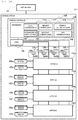
- FIG. 1A is a block diagram showing an example of a configuration of a storage system 100 according to an embodiment of the invention.
- the same parent sign is given to the same kind of element, and in the case of describing the same kind of element individually, a child sign (for example, a to n) is given to the parent sign to explain.
- One or a plurality of (for example, two) host machines 101 are connected to the storage system 100 via a network (not shown).
- the storage system 100 includes one or a plurality of drives 132 (for example, a solid state drive (SSD)) storing data as a non-volatile storage device, one or a plurality of switches (backend switches) 130 which connect the drives 132 , a storage controller 106 that controls the storage system 100 , and a main memory 109 used by the storage controller 106 .
- drives 132 for example, a solid state drive (SSD)
- SSD solid state drive
- switches 130 which connect the drives 132
- storage controller 106 that controls the storage system 100
- main memory 109 main memory 109 used by the storage controller 106 .
- the plurality of switches 130 are connected in order from the storage controller 106 (cascade connection).
- the host machine 101 includes hardware resources, for example, a CPU, a memory, and an I/O port used for transmission with the storage system 100 , which are not shown.
- the host machine 101 can access data of the storage system 100 .
- the drive 132 is a storage device that adopts a data transmission protocol of connection-less transmission (for example, a Peripheral Component Interconnect Express (PCIe)).
- PCIe Peripheral Component Interconnect Express
- the drive 132 When the drive 132 performs data transfer to a data transfer area 116 in the main memory 109 of the storage controller 106 , the data are transmitted via any one of a path 128 a , a path 128 b , a path 128 c , and a path 128 d of each switch 130 .
- the storage controller 106 includes hardware resources such as a CPU 125 and a main memory 109 .
- the main memory 109 of the storage controller 106 stores a drive location table 110 , a request command queue 112 , a response command queue 122 , a storage control program 114 , and a data transmission area 116 .
- the data transmission area 116 stores data read from the drive 132 and data to be written to the drive 132 .
- the data transmission area 116 corresponds all of virtual areas 126 a to 126 d corresponding to the four paths 128 a to 128 d respectively.
- the number of the virtual areas 126 is not limited to four, and can be set according to the number of paths 128 .
- the virtual area 126 is a destination address designated by the drive 132 at the time of data transfer and is associated with the path 128 that transfers data. Further, when the drive 132 specifies the virtual area 126 as the data destination, the actual data destination is the data transmission area 116 .
- the drive 132 a when a drive 132 a specifies the virtual area (0x00) 126 a as the destination address at the time of data transfer, the transferred data is stored in the data transmission area 116 via the path 128 a . Similarly in the other paths 128 b to 128 d , the drive 132 selects each data transfer path by transferring the data to the address of the virtual data transmission area associated with each path.
- the request command queue 112 is an area that stores a request command (for example, a command that issues an instruction for data transfer to the drive 132 ) for the drive 132 generated by the storage controller 106 .
- the response command queue 122 is an area that stores a response command (for example, a response command that indicates completion of the data transfer) for the storage controller 106 from the drive 132 .
- the drive location table 110 is information that specifies switches 130 a to 130 d to which each of drives 132 a to 132 h is connected. As shown in FIG. 1C , the drive location table 110 includes, in one entry, a drive No 1101 that stores an identifier specifying the drive 132 and a switch No 1102 that stores an identifier specifying the switch 130 to which the drive 132 is connected.
- the storage control program 114 is a program that controls data reading/writing process for the drive 132 after receiving an instruction from the host machine 101 . Further, the control program 114 performs initialization of information (for example, the drive location table 110 ) necessary for the invention.
- the storage control program 114 specifies the connected switch 130 for each of drive 132 devices connected via the data transfer path 128 , and stores the identifier of the drive 132 and the identifier of the switch 130 in the drive location table 110 .
- FIG. 1B is a block diagram showing an example of a connection relationship between the switch 130 and the drive 132 of the storage system 100 .
- the switch 130 a is connected to the CPU 125 of the storage controller 106 .
- the drives 132 a and 132 b are connected to the switch 130 a.
- the switch 130 b is connected to the switch 130 a .
- the drives 132 c and 132 d are connected to the switch 130 b .
- the switch 130 c is connected to the switch 130 b .
- the drives 132 e and 132 f are connected to the switch 130 c .
- the switch 130 d is connected to the switch 130 c .
- the drives 132 g and 132 h are connected to the switch 130 d.
- the switches 130 a to 130 d are cascade-connected in order from the CPU 125 of the storage controller 106 .
- the bandwidths of the paths 128 a to 128 d are set equally, for example, set to 8 lanes ( ⁇ 8).
- the switch 130 a includes ports 131 a to 131 d connected to the preceding device (the CPU 125 ), ports 131 e to 131 h connected to the succeeding device (the switch 130 b ), and ports 131 i and 131 j connected to the drives 132 a and 132 b.
- Input ports of demultiplexers 133 b and 133 a are connected to the ports 131 i and 131 j , respectively.
- the ports 131 a to 131 d are connected to output ports of the demultiplexers 133 a and 133 b .
- the demultiplexer 133 a connects the port 131 j and any one of the ports 131 a to 131 d according to the data destination address. The same applies to the demultiplexer 133 b.
- the other switches 130 b to 130 d are constituted similarly to the switch 130 a to switch a connection between the preceding device and the succeeding device or the drive 132 .
- the invention is not limited thereto.
- the data transfer paths 128 a to 128 d are assigned to the virtual areas 126 a to 126 d in advance.
- the path 128 a passes through the port 131 a from port 131 h of the switches 130 a to 130 d and is associated with the data transmission area 116 via the CPU 125 of the storage controller 106 .
- the path 128 b passes through the port 131 b from port 131 g of the switches 130 a to 130 d and is associated with the data transmission area 116 via the CPU 125 of the storage controller 106 .
- the path 128 c passes through the port 131 c from port 131 f of the switches 130 a to 130 d and is associated with the data transmission area 116 via the CPU 125 of the storage controller 106 .
- the path 128 d passes through the port 131 d from port 131 e of the switches 130 a to 130 d and is associated with the data transmission area 116 via the CPU 125 of the storage controller 106 .
- FIG. 1A and FIG. 1B show an example in which four switches 130 are cascade-connected, the number of lanes to be assigned to the paths 128 a to 128 d and a combination of the ports to be used may be changed according to the number of the switches 130 .
- the paths 128 a and 128 b may be assigned to the switch 130 a and the paths 128 c and 128 d may be assigned to the switch 130 b.
- FIG. 2 and FIG. 3 are flowcharts showing an example of a process performed by the storage control program 114 of the storage controller 106 .
- the example of the process of the first embodiment will be described with reference to FIG. 2 and FIG. 3 .
- Each flowchart described below shows an outline of the process within the range necessary for implementation of the invention and may differ from an actual computer program. Further, it is possible to replace steps or to add, change, or delete steps.
- step 200 of FIG. 2 when the storage controller 106 is activated, the storage control program 114 performs initialization to generate the drive location table 110 .
- the storage control program 114 detects that each drive 132 is connected to which of switches 130 a to 130 d and stores the identifier of each switch 130 corresponding to each drive 132 in the drive location table 110 .
- step 205 the storage control program 114 receives an access request from the host machine 101 .
- the storage control program 114 analyzes the access request and specifies the drive 132 of an access target.
- the storage control program 114 proceeds to a process of determining transfer path in step 210 .
- FIG. 3 shows an example of a process of determining transfer path performed in step 210 .
- the storage control program 114 specifies the location of the drive 132 that performs data transfer by referring to the drive location table 110 .
- the location is represented by the number of the switches 130 between the controller 106 and the drive 132 .
- the number one indicates the drive 132 is connected to the switch 130 a
- the number two indicates the drive 132 is connected to the switch 130 b
- the number three indicates the drive 132 is connected to the switch 130 c
- the number four indicates the drive 132 is connected to the switch 130 d.
- the storage control program 114 proceeds to any one of steps 214 to 220 according to the specified location. That is, the storage control program 114 determines the path 128 that transfers data according to the number of the switches 130 between the drive 132 and the controller 106 .
- the storage control program 114 selects the path 128 so as not to select the same paths 128 a to 128 d if the switches 130 a to 130 d to which the drives 132 are connected are different. That is, the first embodiment shows an example in which the paths 128 a to 128 d corresponding to the addresses of the virtual areas 126 a to 126 d to be the destinations are assigned to each of the switches 130 a to 130 d in advance.
- the storage control program 114 specifies that the drive 132 a is connected to the switch 130 a by referring to the drive location table 110 in step 212 of FIG. 3 . Thereafter, the storage control program 114 proceeds to step 220 to designate 0x00 as the data destination address such that the drive 132 a selects the path 128 a as the data transfer path.
- the data transfer path for the drives 132 c to 132 h is selected from paths 128 a to 128 d according to the designated destination address.
- the storage control program 114 proceeds to step 260 in FIG. 2 to generate a request command for the drive 132 , and issue the request command to the drive 132 after storing the request command in the request command queue 112 .
- step 280 the storage control program 114 refers to the response command queue 122 , proceeds to step 282 if there is a response from the drive 132 , and returns to step 280 if there is no response.
- step 282 the storage control program 114 completes the process of the request command issued in step 260 by reading the response command from the drive 132 stored in the response command queue 122 .
- steps 205 to 282 can be repeatedly executed each time the storage controller 106 receives the access request from the host machine 101 .
- FIG. 4 is a diagram showing an example of a packet of PCIe transferred by the path 128 .
- the illustrated example shows a transaction layer packet 160 of PCIe.
- the transaction layer packet 160 of PCIe includes a header 161 , data 162 , and an end to end Cyclic Redundancy Check (ECRC) 163 .
- ECRC Cyclic Redundancy Check
- the destination address designated by the storage controller 106 in steps 214 to 220 of FIG. 3 indicating the virtual area 126 is set in a destination address 164 in the header 161 in FIG. 4 .
- the data transferred by the drive 132 that processes and responds the request from the storage controller 106 are divided into packets as in FIG. 4 , and are given to the header 161 of each packet by the destination address 164 .
- the transfer path can be selected according to the destination address 164 .
- the path used by the storage device connected to the successor switch can also be used by the storage device connected to the predecessor switch.
- the transfer of the storage device connected to the successor switch may be hindered by the transfer of the storage device connected to the predecessor switch and the transfer from the storage device connected to the successor switch may be delayed. This is an example in which the performance difference between the storage devices occurs in the predecessor and the successor backend switches described as the problem.
- the storage controller 106 equally assigns the plurality of virtual areas 126 a to 126 d to the drive 132 of an access target according to the number of the switches 130 between the controller 106 and the drive 132 to separate the data transfer path 128 for each switch 130 .
- each drive 132 selects the paths 128 a to 128 d that performs the data transfer according to the data destination address (the virtual area 126 ) of the main memory 109 designated by the storage controller 106 .
- the paths 128 a to 128 d connected with the switch 130 are assigned to the plurality of virtual areas 126 a to 126 d with the same bandwidth. Accordingly, the performance difference between the drives 132 a to 132 h connected to each of switches 130 a to 130 d can be eliminated by separating the data transfer path 128 between the plurality of switches 130 and assigning the same bandwidth.
- the all four paths 128 a to 128 d are assigned to the drive 132 of the switch 130 a.
- the storage controller 106 assigns the paths 128 a and 128 b to the drives 132 connected to the switch 130 a , and assigns the paths 128 a , 128 b to the drives 132 connected to the switch 130 b . Accordingly, in the storage system 100 using the connection-less protocol, the added switch 130 b can also establish the same bandwidth as the existing switch 130 a.
- the switch 130 may be a relay device as long as the relay device is cascade-connected in group units and includes one or more drives 132 .
- the relay device in which the drives 132 a , 132 b are connected to the storage controller 106 as a first group and the drives 132 c , 132 d are connected to the first group as a second group. Accordingly, in the storage system 100 adopting a connection-less protocol, a plurality of groups are cascade-connected and the independent data transfer paths 128 are assigned to each group in the same bandwidth so that the performance difference of the drives 132 between groups can be eliminated by making the drive 132 of each group select the different path 128 .
- a second embodiment of the invention will be described with reference to FIG. 5A to FIG. 7 .
- the second embodiment corresponds to a modification of the first embodiment.
- FIG. 5A is a block diagram showing an example of a configuration of the storage system 100 of the second embodiment.
- a path-switch table 118 is added to the main memory 109 in FIG. 1 shown in the first embodiment, and the other configuration is the same as that of the first embodiment.
- the second embodiment shows an example in which the maximum number of switches 130 is set to 4.
- FIG. 5B is a diagram showing an example of the path-switch table 118 .
- the path-switch table 118 stores the number of valid paths 1181 cascade-connected from the storage controller 106 and the number of valid switches 1182 cascade-connected from the storage controller 106 .
- FIG. 6A is a flowchart showing an example of a process performed in the storage system 100 according to the second embodiment.
- the storage control program 114 performs initialization to generate the drive location table 110 .
- the storage control program 114 detects a location to which of switches 130 a to 130 d each drive 132 is connected and stores an identifier of each switch 130 corresponding to each drive 132 in the drive location table 110 . In addition, in step 390 , the storage control program 114 stores the number of the valid paths 128 and the number of the valid switches 130 in the path-number of switches table 118 .
- step 395 the storage control program 114 receives an access request from the host machine 101 .
- the storage control program 114 analyzes the access request and specifies the drive 132 to be accessed.
- FIG. 7 is a flowchart showing an example of a process of determining the transfer path performed in step 300 .
- the storage control program 114 calculates a quotient of the number of the valid paths 1181 and the number of the valid switches 1182 from the path-number of switches table 118 .
- the storage control program 114 proceeds to step 302 when the quotient is 1, proceeds to step 304 when the quotient is 2, and proceeds to step 318 when the quotient is 4.
- step 302 where the quotient is 1, the storage control program 114 specifies the location of the drive 132 that performs data transfer by referring to the drive location table 110 . Thereafter, the storage control program 114 proceeds to any one of steps 306 to 312 according to the specified location. The storage control program 114 determines the paths 128 a to 128 d according to the number of the switches 130 between the controller 106 and the drive 132 .
- the path 128 is selected so as not to select the same paths 128 a to 128 d if the switches 130 a to 130 d to which the drives 132 are connected are different.
- the paths 128 a to 128 d corresponding to the addresses of the virtual areas 126 a to 126 d to be the destinations are assigned in advance to each of the switches 130 a to 130 d.
- the storage control program 114 determines that the drive 132 a is connected to the switch 130 a by referring to the drive location table 110 in step 302 in FIG. 7 .
- step 312 designate 0x00 as the data destination address such that the drive 132 a selects the path 128 a as the data transfer path.
- the storage control program 114 proceeds to any one of steps 306 , 308 and 310 to designate the destination address of the drive 132 as anyone of 0x04, 0x08 and 0x0C by referring to the drive location table 110 .
- the data transfer path for the drives 132 c to 132 h is selected from paths 128 a to 128 d by the drives 132 c to 132 h according to the designated destination address. Thereafter, the storage control program 114 proceeds to step 360 in FIG. 6A .
- step 304 where the quotient is 2 the storage control program 114 specifies the location of the drive 132 that performs data transfer by referring to the drive location table 110 . Thereafter, the storage control program 114 proceeds to any one of steps 314 and 316 according to the specified location to determine the path 128 according to the number of the switches 130 between the controller 106 and the drive 132 .
- the path 128 is selected so as not to use the same paths 128 a to 128 d if the switch 130 to which the drive 132 is connected is different.
- the storage control program 114 proceeds to step 316 .
- step 316 the storage control program 114 designates 0x00 or 0x04 as the destination address of the drive 132 such that the drive 132 selects the path 128 a or 128 b as the data transfer path. Thereafter, the storage control program 114 proceeds to step 360 in FIG. 6A .
- step 304 When specifying that the drive 132 is connected to the switch 130 b in step 304 , the storage control program 114 proceeds to step 314 .
- step 314 the storage control program 114 designates 0x08 or 0x0C as the destination address of the drive 132 such that the drive 132 selects the path 128 c or 128 d as the data transfer path. Thereafter, the storage control program 114 proceeds to step 360 in FIG. 6A .
- step 318 where the quotient is 4, 0x0C or 0x08 or 0x04 or 0x00 is designated as the destination address of the drive 132 such that the drive 132 selects any one of the path 128 d , path 128 c , path 128 b , and path 128 a as the data transfer path.
- the storage control program 114 proceeds to step 360 in FIG. 6A .
- Step 360 is the same process as step 260 in FIG. 2 and the storage control program 114 issues the request command to the drive 132 .
- FIG. 6B is a flowchart showing an example of a process of updating a path-number of switches table performed in step 370 .
- step 372 in FIG. 6B the storage control program 114 determines whether there is a change in the number of paths 128 or the number of switches 130 , proceeds to step 374 if there is a change, and proceeds to step 395 again if there is no change.
- step 374 the storage control program 114 updates the number of the changed paths 128 or an entry of the path-number of switches table 118 corresponding to the changed switch 130 .
- step 370 includes the processes of steps 280 , 282 shown in the first embodiment.
- the storage control program 114 selects the paths 128 a to 128 d that performs data transfer according to the number of the switches 130 between the storage controller 106 and the drive 132 . Accordingly, the performance difference between the drives 132 a to 132 h connected to each of switches 130 a to 130 d can be eliminated by separating the data transfer path 128 between the plurality of switches 130 .
- FIG. 8 is a flowchart showing an example of a process of determining the transfer path performed in step 300 shown in FIG. 6A of the second embodiment.
- FIG. 8 to FIG. 10 show an example of a process performed in step 300 in the third embodiment.
- step 320 of FIG. 8 the storage control program 114 calculates a quotient of the number of the valid paths 1181 and the number of the valid switches 1182 from the path-number of switches table 118 .
- the storage control program 114 proceeds to step 330 when the quotient is 1, proceeds to step 340 when the quotient is 2, and proceeds to step 350 when the quotient is 4.
- FIG. 9 is a flowchart showing an example of a process performed in step 330 .
- the storage control program 114 refers to the drive location table 110 and calculates the ratio of the number of drives 132 connected to each of the switches 130 . Then, the storage control program 114 performs branching according to the calculated ratio.
- the storage control program 114 proceeds to step 334 to equally designate a destination address of the drive 132 connected to the switch 130 a as any one of 0x0 to 0xC. Accordingly, the drive 132 connected to the switch 130 a executes data transfer by any one of the paths 128 a to 128 d.
- the storage control program 114 proceeds to step 336 to equally designate the destination address of the drive 132 connected to the switch 130 a as any one of 0x00 to 0x08, and designate the destination address of the drive 132 connected to the switch 130 b as 0x0C. Accordingly, the drive 132 connected to the switch 130 a executes the data transfer by any one of the paths 128 a to 128 c and the drive 132 connected to the switch 130 b executes the data transfer by the path 128 d.
- the storage control program 114 proceeds to step 338 when the ratio of the number of the drives 132 connected to each of the switches 130 is 2:1:1:0. First, the storage control program 114 equally designates the destination address of the drive 132 connected to the switch 130 a as any one of 0x00 and 0x04, designates the destination address of the drive 132 connected to the switch 130 b as 0x08, and designates the destination address of the drive 132 connected to the switch 130 c as 0x0C.
- the drive 132 of the switch 130 a executes the data transfer by any one of the path 128 a and the path 128 b
- the drive 132 connected the switch 130 b executes the data transfer by the path 128 c
- the drive 132 connected to the switch 130 c executes the data transfer by the path 128 d.
- the storage control program proceeds to step 339 .
- the storage control program 114 designates the destination address of the drive 132 connected to the switch 130 a as 0x00, designates the destination address of the drive 132 connected to the switch 130 b as 0x04, designates the destination address of the drive 132 connected to the switch 130 c as 0x08, and designates the destination address of the drive 132 connected to the switch 130 d as 0x0C.
- the drive 132 connected to the switch 130 a executes the data transfer by the path 128 a
- the drive 132 connected to the switch 130 b executes the data transfer by the path 128 b
- the drive 132 connected to the switch 130 c executes the data transfer by the path 128 c
- the drive 132 connected to the switch 130 d executes the data transfer by the path 128 d.
- step 330 After the above process, a series of processes in step 330 are ended, thereafter a series of processes in step 300 are ended.
- FIG. 10 is a flowchart showing an example of a process performed in step 340 .
- the quotient is 2, and there are two of the switches 130 in the third embodiment.
- step 342 the storage control program 114 refers to the drive location table 110 and calculates the ratio of the number of drives 132 connected to each of the switches 130 a and 130 b.
- the storage control program 114 proceeds to step 344 to designate the destination address of the drive 132 connected to the switch 130 a as any one of 0x0 to 0xC.
- the storage control program 114 proceeds to step 346 to designate the destination address of the drive 132 connected to the switch 130 a as any one of 0x00 to 0x08, and designate the destination address of the drive 132 connected to the switch 130 b as 0x0C.
- the drive 132 connected to the switch 130 a executes the data transfer by any one of the paths 128 a to 128 c and the drive 132 connected to the switch 130 b executes the data transfer by the path 128 d.
- the storage control program 114 proceeds to step 348 to designate the destination address of the drive 132 connected to the switch 130 a as any one of 0x00 and 0x04, and designate the destination address of the drive 132 connected to the switch 130 b as 0x08 and 0x0C.
- the drive 132 connected to the switch 130 a executes the data transfer by any one of the paths 128 a , 128 b
- the drive 132 connected to the switch 130 b executes the data transfer by the path 128 c or the path 128 d.
- the storage control program 114 ends a series of process in step 340 , and thereafter ends a series of process in step 300 .
- step 350 in FIG. 8 since the number of the switch 130 is one, the storage control program 114 designates 0x00 to 0x0C as the data destination addresses such that the drive 132 connected to the switch 130 a selects the paths 128 a to 128 d as the data transfer path.
- the storage control program 114 ends a series of processes in step 300 .
- the storage control program 114 selects the paths 128 a to 128 d that performs data transfer according to the ratio of the number of the switches 130 between the storage controller 106 and the drive 132 . Accordingly, the performance difference between the drives 132 a to 132 h connected to each of switches 130 a to 130 d can be eliminated by separating the data transfer paths 128 between the plurality of switches 130 .
- FIG. 11A is a block diagram showing an example of a configuration of the storage system 100 in the fourth embodiment.
- a path failure detection circuit 127 is added to the storage controllers 106 in FIG. 5A shown in the second embodiment and a path status table 117 that records whether each of the paths 128 is normal or unusable is added to the main storage 109 .
- the path failure detection circuit 127 notifies the CPU 125 which of the paths 128 are normal via a path status signal line 119 . Further, the path failure detection circuit 127 detects if each of the paths 128 becomes unusable due to an failure or the like and notifies the CPU 125 of that via the path status signal line 119 .
- the other configurations are the same as those in the second embodiment.
- FIG. 11B is a diagram showing an example of the path status table 117 .
- the path status table 117 includes, in one entry, the path number 1171 that stores an identifier of each of the paths 128 and a status 1172 that stores the status of each of the paths 128 .
- FIG. 12A is a flowchart showing an example of a process performed in the storage system 100 according to the fourth embodiment.
- the storage control program 114 performs initialization to generate the drive location table 110 and the path status table 117 .
- step 490 the storage control program 114 detects that each drive 132 is connected to which of switches 130 a to 130 d and records the identifier of each switch 130 corresponding to each drive 132 in the drive location table 110 .
- step 490 the storage control program 114 records the number of the valid paths 128 and the number of the valid switches 130 in the path-number of switches table 118 . Further, the path failure detection circuit 127 detects whether each of the paths 128 a to 128 d is normal or unusable, and stores each detection result in the path status table 117 .
- step 495 the storage control program 114 receives an access request from the host machine 101 .
- the storage control program 114 analyzes the access request and specifies the drive 132 to be accessed.
- FIG. 13 is a flowchart showing an example of a process of determining the transfer path performed in step 400 .
- step 401 the storage control program 114 calculates a quotient of the number of normal paths 128 and the number of valid switches 130 from the path status table 117 and the path-number of switches table 118 .
- the storage control program 114 proceeds to step 402 when the quotient is 1, proceeds to step 404 when the quotient is 2, and proceeds to step 418 when the quotient is 4.
- step 402 the storage control program 114 specifies the location (the number of switches 130 between the storage controller 106 and the drive 132 ) of the drive 132 that performs data transfer by referring to the drive location table 110 . Thereafter, the storage control program 114 determines any one of the paths 128 a to 128 d according to the number of the switches 130 between the storage controller 106 and the drives 132 .
- the storage control program 114 proceeds to step 405 . If the drive 132 is connected to the switch 130 c (the third switch), the storage control program 114 proceeds to step 407 . If the drive 132 is connected to the switch 130 b (the second switch), the storage control program 114 proceeds to step 409 . If the drive 132 is connected to the switch 130 a (the first stage), the storage control program 114 proceeds to step 411 .
- the storage control program 114 determines whether the path 128 corresponding to the location of the drive 132 is normal or not by referring to the path status table 117 .
- the path 128 d is selected if the drive 132 is connected to the fourth switch 130 d
- the path 128 c is selected if the drive 132 is connected to the third switch 130 c
- the path 128 b is selected if the drive 132 is connected to the second switch 130 b
- the path 128 a is selected if the drive 132 is the first switch 130 a.
- the storage control program 114 proceeds to steps 406 , 408 , 410 , and 412 corresponding to the paths 128 to designate the destination address if the selected path 128 is normal.
- the storage control program 114 selects a normal one from the paths 128 and designates the destination address corresponding to the selected one of paths 128 .
- step 405 the storage control program 114 proceeds to step 407 to determine the status of the path 128 c if the path 128 d is unusable. Then the storage control program 114 proceeds to step 408 to perform data transfer of the drive 132 connected to the fourth switch 130 d by the path 128 c if the status of the path 128 c is normal. Thereafter, the storage control program 114 proceeds to step 460 in FIG. 12A .
- step 404 where the quotient is 2 the storage control program 114 specifies the location of the drive 132 that performs data transfer by referring to the drive location table 110 .
- the storage control program 114 select two paths from the paths 128 according to the number of the switches 130 between the storage controller 106 and the drive 132 .
- the storage control program 114 proceeds to step 413 if the drive 132 is connected to the switch 130 b (the second switch), and proceeds to step 415 if the drive 132 is connected to the switch 130 a (the first switch).
- the storage control program 114 designates the destination address by referring to the path status table 117 in steps 413 or 415 such that the data transfer can be performed by using the other two paths of paths 128 when both the selected two paths of paths 128 are unusable.
- step 413 if both the path 128 c and 128 d are unusable, the storage control program 114 proceeds to step 415 to determine the status of the path 128 b and the path 128 a . Further, if the status of the path 128 b or the path 128 a is normal, the storage control program 114 proceeds to step 416 .
- the storage control program 114 designates the destination address corresponding to the path 128 b or the path 128 a of the data transfer of the drive 132 connected to the second switch 130 b . Thereafter, the storage control program 114 proceeds to step 460 .
- step 418 where the quotient is 4 the storage control program 114 designates 0x0C or 0x08 or 0x04 or 0x00 as the destination address of the drive 132 such that the drive 132 selects the path 128 d or the path 128 c or the path 128 b or the path 128 a as the data transfer path.
- the destination address is designated by referring to the path status table 117 such that the data transfer can be performed using the normal path.
- the storage control program 114 proceeds to step 460 .
- Step 460 is the same process as step 260 in FIG. 2 and the storage control program 114 issues the request command to the drive 132 .
- FIG. 12B is a flowchart showing an example of a process performed in step 450 .
- step 452 in FIG. 12B the storage control program 114 determines whether there is a change in the number of paths 128 or the number of switches 130 , proceeds to step 454 if there is a change, and proceeds to step 456 if there is no change.
- step 454 the storage control program 114 updates the number of the changed paths 128 or the number of the changed switches 130 in the corresponding entry of the path-number of switches table 118 , and proceeds to step 456 .
- step 456 the path failure detection circuit 127 determines whether there is a change in the status of the path 128 , the storage control program 114 proceeds to step 458 if there is a change, and proceeds to step 495 in FIG. 12A if there is no change.
- step 458 the entry in the path status table 117 corresponding to the changed path 128 is updated, and the storage control program 114 returns to step 495 in FIG. 12A to repeat the above process. It is assumed that the process of step 450 includes the processes of steps 280 and 282 shown in the first embodiment.
- the storage control program 114 switches to the normal one of paths 128 to perform the data transfer if the path 128 corresponding to the number of the switches 130 between the storage controllers 106 and the drive 132 is unusable. Accordingly, even when a failure occurs in one of the path 128 , the performance difference between the drives 132 a to 132 h connected to the switches 130 a to 130 d can be eliminated by separating the data transfer paths 128 among the plurality of switches 130 .
- FIG. 14A is a block diagram showing an example of a configuration of the storage system 100 of the fifth embodiment.
- FIG. 14A of the fifth embodiment a supervisor terminal 104 and a storage system management program 108 are added to the storage system 100 shown in FIG. 1 of the first embodiment, further, a path selection table 150 is added to the main memory 109 of the storage controller 106 .
- the other configurations are the same as those in the first embodiment.
- the supervisor terminal 104 is a computer that includes hardware resources, for example, a CPU, an input/output device, a memory, and an interface, which are not shown.
- the CPU of the supervisor terminal 104 can control the storage system 100 (for example, operation instructions such as acquisition and change of configuration information) by executing the storage system management program 108 loaded in the memory.
- the path selection table 150 is a table used for designating a path for the data transfer of the drives 132 connected to the switches 130 .
- the supervisor terminal 104 can register identifiers of the paths 128 a to 128 d that transfer the data of the drives 132 for each switch 130 in the path selection table 150 .
- FIG. 14B is a diagram showing an example of the path selection table 150 .
- the path selection table 150 includes, in one entry, a switch number 1501 that stores the identifier of the switches 130 and a path 1502 that stores the identifier of the path 128 assigned to the switches 130 .
- FIG. 15 is a flowchart showing an example of a process performed in the storage system 100 according to the fifth embodiment.
- the storage control program 114 detects that each drive 132 is connected to which of switches 130 a to 130 d and records the identifier of each switch 130 corresponding to each drive 132 in the drive location table 110 .
- step 580 the storage control program 114 receives the path selection information from the supervisor terminal 104 and updates the path selection table 150 .
- the storage control program 114 registers which one of the paths 128 used for each of the drives 132 by each of switches 130 in the path selection table 150 .
- a path a (the path 128 a ) is set to the first switch 130 a
- a path b (the path 128 b ) is set to the second switch 130 b
- a path c (the path 128 c ) is set to the third switch 130 c
- a path d (the path 128 d ) is set to the fourth switch 130 d.
- step 585 the storage control program 114 receives an access request from the host machine 101 .
- the storage control program 114 analyzes the access request and specifies the drive 132 to be accessed.
- FIG. 16 is a flowchart showing an example of a process of determining the transfer path performed in step 500 .
- step 502 of FIG. 16 the storage control program 114 specifies the switch 130 to which the specified one of the drives 132 is connected, by referring to the drive location table 110 , and proceeds to step 504 .
- step 504 the storage control program 114 specifies the path 128 used by the drive 132 for data transfer by referring to the entry in the path selection table 150 . Thereafter, the storage control program 114 proceeds to any one of steps 506 to 510 according to the specified one of the paths 128 a to 128 d to designate a destination address corresponding to the path 128 used for data transfer. Thereafter, the storage control program 114 proceeds to step 560 in FIG. 15 .
- Step 560 is the same process as step 260 in FIG. 2 and the storage control program 114 issues the request command to the drive 132 . After issuing the request command, the processes of steps 280 and 282 shown in the first embodiment are executed although not shown. Thereafter, the storage control program 114 returns to the step 580 to repeat the above process.
- the path selection table 150 can be updated by the supervisor terminal 104 even while the storage controller 106 performs the data transfers for the drives 130 .
- FIG. 17A to FIG. 19 A sixth embodiment of the invention will be described with reference to FIG. 17A to FIG. 19 .
- Each of the following embodiments including the present embodiment corresponds to a modification on the first embodiment.
- FIG. 17A is a block diagram showing an example of a configuration of the storage system 100 in the sixth embodiment.
- a load information table 120 that stores a load information of each switch 130 to which the drive 132 is connected is added to the main memory 109 of the storage controller 106 of the FIG. 1 shown in the first embodiment.
- the load information table 120 records the sum total of the number of commands being issued to each drive 132 by the switch 130 to which the drive 132 is connected.
- the other configurations are the same as those in the first embodiment.
- FIG. 17B is a diagram showing an example of the load information table 120 .
- the load information table 120 includes, in one entry, a switch number 1201 that stores a location or an identifier of the switch 130 and the number of commands being issued 1202 that stores the number of commands being issued to the drive 132 connected to the switch 130 .
- FIG. 18 is a flowchart showing an example of a process performed in the storage system 100 according to the sixth embodiment.
- the storage control program 114 detects that each drive 132 is connected to which of switches 130 and records the identifier of each switch 130 corresponding to each drive 132 in the drive location information table 110 . Further, in step 690 , the storage control program 114 initializes all entries in the load information table 120 with 0.
- step 695 the storage control program 114 receives an access request from the host machine 101 .
- the storage control program 114 analyzes the access request and specifies the drive 132 to be accessed.
- Step 610 is the same process of determining transfer path as step 210 shown in FIG. 2 of the first embodiment, and the destination address corresponding to the determined path 128 is designated.
- Step 660 is the same process as step 260 shown in FIG. 2 of the first embodiment and the storage control program 114 issues the request command to the drive 132 .
- FIG. 19 is a flowchart showing an example of a process performed in step 600 in FIG. 18 .
- step 602 in FIG. 19 the storage control program 114 increases the number of commands being issued 1202 in the entry of the load information table 120 corresponding to the switch 130 to which the drive 132 accessed in the request command is connected.
- the value of the number of commands being issued 1202 indicates the load of the switch 130 .
- step 604 the storage control program 114 refers to the response command queue 122 , proceeds to step 606 if there is a response from the drive 132 connected to the switch 130 , and proceeds to step 622 in FIG. 18 if there is no response.
- step 606 when the drive 132 completes the data transfer to the data transfer area 116 , the response command is stored in the response command queue 122 , and the storage control program 114 completes the process of the request command issued in step 660 by removing the response command from the response command queue 122 .
- step 608 the storage control program 114 decreases the number of commands being issued 1202 of the entry of the load information table 120 corresponding to the drive 132 corresponding to the request command completed in step 606 . Thereafter, the storage control program 114 proceeds to step 622 in FIG. 18 .
- step 622 in FIG. 18 the storage control program 114 refers to the load information table 120 and calculates the sum total value of the number of commands being issued to the drives 132 c to 132 h connected to the switches 130 b to 130 d , and proceeds to step 624 if the sum total value is 0.
- step 624 the storage control program 114 changes the destination addresses of the drives 132 a and 132 b connected to the first switch 130 a as anyone of 0x00 to 0x0C, and returns to step 695 to repeat the above process.
- step 622 if the sum total value of the number of commands being issued to the drives 132 c to 132 h connected to the switches 130 b to 130 d is not 0, the storage control program 114 returns to step 695 again to repeat the above process.
- the storage control program 114 can monitor the load of the switch 130 connected to the storage controller 106 and change the path 128 according to the load.
- the invention is not limited to each of the above-described embodiments, and includes various modifications.
- the above-described embodiments have been described in detail for easy understanding of the invention, and are not necessarily limited to those including all the configurations described above.
- a part of a configuration of a certain embodiment can be replaced with a configuration of the other embodiments and the configuration of the other embodiments can be added to the configuration of the certain embodiment.
- other configurations may be added to, deleted from or replaced with a part of a configuration of each embodiment, which can be applied alone or in combination.
- configurations, functions, processing units, processing means, or the like may be achieved by hardware by means of designing a part or all of them with, for example, an integrated circuit. Further, the configurations, functions, or the like may be achieved by software by means of interpreting and executing a program by a processor used for achieving the respective functions. Information such as a program, a table, and a file used for achieving the functions can be stored in a recording device such as a memory, a hard disk and a solid state drive (SSD), or a recording medium such as an IC card, an SD card, and a DVD.
- SSD solid state drive
- control line and an information line are shown in consideration of necessity for description, and not all control lines and information lines are necessarily shown in the device. In practice, it may be considered that almost all the configurations are connected with each other.
Landscapes
- Engineering & Computer Science (AREA)
- Theoretical Computer Science (AREA)
- Physics & Mathematics (AREA)
- General Engineering & Computer Science (AREA)
- General Physics & Mathematics (AREA)
- Human Computer Interaction (AREA)
- Mathematical Physics (AREA)
- Computer Hardware Design (AREA)
- Computer Networks & Wireless Communication (AREA)
- Microelectronics & Electronic Packaging (AREA)
- Multi Processors (AREA)
Abstract
Description
Claims (14)
Applications Claiming Priority (1)
| Application Number | Priority Date | Filing Date | Title |
|---|---|---|---|
| PCT/JP2017/007282 WO2018154743A1 (en) | 2017-02-27 | 2017-02-27 | Storage system and storage control method |
Publications (2)
| Publication Number | Publication Date |
|---|---|
| US20190258599A1 US20190258599A1 (en) | 2019-08-22 |
| US10732872B2 true US10732872B2 (en) | 2020-08-04 |
Family
ID=63253643
Family Applications (1)
| Application Number | Title | Priority Date | Filing Date |
|---|---|---|---|
| US16/329,570 Active US10732872B2 (en) | 2017-02-27 | 2017-02-27 | Storage system and storage control method |
Country Status (2)
| Country | Link |
|---|---|
| US (1) | US10732872B2 (en) |
| WO (1) | WO2018154743A1 (en) |
Families Citing this family (2)
| Publication number | Priority date | Publication date | Assignee | Title |
|---|---|---|---|---|
| US11003357B2 (en) * | 2019-09-13 | 2021-05-11 | EMC IP Holding Company LLC | Managing single path communication between a host and a storage system |
| KR20210046348A (en) * | 2019-10-18 | 2021-04-28 | 삼성전자주식회사 | Memory system for flexibly allocating memory for multiple processors and operating method thereof |
Citations (18)
| Publication number | Priority date | Publication date | Assignee | Title |
|---|---|---|---|---|
| US6195354B1 (en) * | 1997-07-16 | 2001-02-27 | Nortel Networks Limited | Route selection for path balancing in connection-oriented packet switching networks |
| US20070220204A1 (en) | 2006-03-20 | 2007-09-20 | Hitachi, Ltd. | Computer system for controlling allocation of physical links and method thereof |
| US20080059687A1 (en) * | 2006-08-31 | 2008-03-06 | Peter Mayer | System and method of connecting a processing unit with a memory unit |
| US20080126698A1 (en) * | 2006-09-13 | 2008-05-29 | Hitachi, Ltd. | Storage system effectively using free ports |
| US20090031057A1 (en) * | 2007-07-24 | 2009-01-29 | International Business Machines Corporation | Methods, systems and computer products for user-managed multi-path performance in balanced or unbalanced fabric configurations |
| US20090147673A1 (en) | 2007-12-05 | 2009-06-11 | Fujitsu Limited | Storage system and route switch |
| US20090259791A1 (en) | 2008-04-14 | 2009-10-15 | Hitachi, Ltd. | Adjustment number of expanders in storage system |
| US20120191921A1 (en) * | 2009-12-14 | 2012-07-26 | Ian Shaeffer | Expandable asymmetric-channel memory system |
| US20130311719A1 (en) * | 2012-05-18 | 2013-11-21 | Atto Technology, Inc. | Target path selection for storage controllers |
| US20130332767A1 (en) * | 2012-06-12 | 2013-12-12 | International Business Machines Corporation | Redundancy and load balancing in remote direct memory access communications |
| WO2014039922A2 (en) | 2012-09-06 | 2014-03-13 | Pi-Coral, Inc. | Large-scale data storage and delivery system |
| US8880715B2 (en) * | 2008-10-23 | 2014-11-04 | Canon Kabushiki Kaisha | Remote control of a host computer |
| WO2015045030A1 (en) | 2013-09-25 | 2015-04-02 | 株式会社日立製作所 | Information system capable of adding drives, and bus number allocation method for said information system |
| WO2015136619A1 (en) | 2014-03-11 | 2015-09-17 | 株式会社日立製作所 | Storage device |
| US20170177264A1 (en) * | 2015-12-22 | 2017-06-22 | EMC IP Holding Company LLC | Method and apparatus for path selection of storage systems |
| US20180059987A1 (en) * | 2016-08-31 | 2018-03-01 | Samsung Electronics Co., Ltd. | Method for reducing read buffer size requirements in nvme based solid state drives |
| US10067794B1 (en) * | 2013-05-03 | 2018-09-04 | EMC IP Holding Company LLC | Computer-executable method, system, and computer program product for balanced port provisioning using filtering in a data storage system |
| US20190146684A1 (en) * | 2017-11-13 | 2019-05-16 | Western Digital Technologies, Inc. | System and method for qos over nvme virtualization platform using adaptive command fetching |
-
2017
- 2017-02-27 WO PCT/JP2017/007282 patent/WO2018154743A1/en not_active Ceased
- 2017-02-27 US US16/329,570 patent/US10732872B2/en active Active
Patent Citations (24)
| Publication number | Priority date | Publication date | Assignee | Title |
|---|---|---|---|---|
| US6195354B1 (en) * | 1997-07-16 | 2001-02-27 | Nortel Networks Limited | Route selection for path balancing in connection-oriented packet switching networks |
| US20070220204A1 (en) | 2006-03-20 | 2007-09-20 | Hitachi, Ltd. | Computer system for controlling allocation of physical links and method thereof |
| JP2007256993A (en) | 2006-03-20 | 2007-10-04 | Hitachi Ltd | Computer system and method for controlling allocation of physical links |
| US20080059687A1 (en) * | 2006-08-31 | 2008-03-06 | Peter Mayer | System and method of connecting a processing unit with a memory unit |
| US20080126698A1 (en) * | 2006-09-13 | 2008-05-29 | Hitachi, Ltd. | Storage system effectively using free ports |
| US20090031057A1 (en) * | 2007-07-24 | 2009-01-29 | International Business Machines Corporation | Methods, systems and computer products for user-managed multi-path performance in balanced or unbalanced fabric configurations |
| US20090147673A1 (en) | 2007-12-05 | 2009-06-11 | Fujitsu Limited | Storage system and route switch |
| JP2009140179A (en) | 2007-12-05 | 2009-06-25 | Fujitsu Ltd | Storage system and root switch |
| US20090259791A1 (en) | 2008-04-14 | 2009-10-15 | Hitachi, Ltd. | Adjustment number of expanders in storage system |
| JP2009258841A (en) | 2008-04-14 | 2009-11-05 | Hitachi Ltd | Storage system |
| US8880715B2 (en) * | 2008-10-23 | 2014-11-04 | Canon Kabushiki Kaisha | Remote control of a host computer |
| US20120191921A1 (en) * | 2009-12-14 | 2012-07-26 | Ian Shaeffer | Expandable asymmetric-channel memory system |
| US20130311719A1 (en) * | 2012-05-18 | 2013-11-21 | Atto Technology, Inc. | Target path selection for storage controllers |
| US20130332767A1 (en) * | 2012-06-12 | 2013-12-12 | International Business Machines Corporation | Redundancy and load balancing in remote direct memory access communications |
| WO2014039922A2 (en) | 2012-09-06 | 2014-03-13 | Pi-Coral, Inc. | Large-scale data storage and delivery system |
| JP2015532985A (en) | 2012-09-06 | 2015-11-16 | ピーアイ−コーラル、インク. | Large-scale data storage and delivery system |
| US10067794B1 (en) * | 2013-05-03 | 2018-09-04 | EMC IP Holding Company LLC | Computer-executable method, system, and computer program product for balanced port provisioning using filtering in a data storage system |
| WO2015045030A1 (en) | 2013-09-25 | 2015-04-02 | 株式会社日立製作所 | Information system capable of adding drives, and bus number allocation method for said information system |
| US20160117281A1 (en) | 2013-09-25 | 2016-04-28 | Hitachi, Ltd. | Information system capable of expanding drive and bus number allocation method of the information system |
| WO2015136619A1 (en) | 2014-03-11 | 2015-09-17 | 株式会社日立製作所 | Storage device |
| US20150350322A1 (en) | 2014-03-11 | 2015-12-03 | Hitachi, Ltd. | Storage subsystem |
| US20170177264A1 (en) * | 2015-12-22 | 2017-06-22 | EMC IP Holding Company LLC | Method and apparatus for path selection of storage systems |
| US20180059987A1 (en) * | 2016-08-31 | 2018-03-01 | Samsung Electronics Co., Ltd. | Method for reducing read buffer size requirements in nvme based solid state drives |
| US20190146684A1 (en) * | 2017-11-13 | 2019-05-16 | Western Digital Technologies, Inc. | System and method for qos over nvme virtualization platform using adaptive command fetching |
Non-Patent Citations (2)
| Title |
|---|
| "SAS as a budding fabric." Embedded Computing Design. Online Oct. 12, 2007. Retrieved from Internet Mar. 13, 2020. <http://embedded-computing.com/article-id/?2258=>. (Year: 2020). * |
| International Search Report dated May 30, 2017 for the International Application No. PCT/JP2017/007282. |
Also Published As
| Publication number | Publication date |
|---|---|
| WO2018154743A1 (en) | 2018-08-30 |
| US20190258599A1 (en) | 2019-08-22 |
Similar Documents
| Publication | Publication Date | Title |
|---|---|---|
| US8412863B2 (en) | Storage apparatus and virtual port migration method for storage apparatus | |
| JP6958440B2 (en) | Information processing equipment, information processing systems and programs | |
| CN101042632B (en) | Computer system and method for controlling allocation of physical links | |
| US8977781B1 (en) | Computer system | |
| US10102169B2 (en) | System and method for port migration in a PCIE switch | |
| US8285913B2 (en) | Storage apparatus and interface expansion authentication method therefor | |
| US9253257B2 (en) | Storage subsystem | |
| US7395388B2 (en) | Load balancing system and method | |
| US9959051B2 (en) | Storage system and storage control method to select path for transmitting command via SAS expanders | |
| US20120233399A1 (en) | Storage apparatus and method of controlling the same | |
| WO2012073304A1 (en) | Computer system, and switch and packet transfer control method used therein | |
| US9875059B2 (en) | Storage system | |
| US9354815B2 (en) | Computer realizing high-speed access and data protection of storage device, computer system, and I/O request processing method | |
| JP7197545B2 (en) | Storage system and storage system control method | |
| US10452292B2 (en) | Computer system | |
| CN119452339A (en) | Method and system for updating device firmware while maintaining state and connectivity | |
| US8402195B2 (en) | Storage system mounted with plurality of processors | |
| US10732872B2 (en) | Storage system and storage control method | |
| US10241950B2 (en) | Multipath I/O proxy device-specific module | |
| JP5182162B2 (en) | Computer system and I/O control method | |
| US8745448B2 (en) | Storage system, storage control apparatus and method for failure recovery | |
| JP5511546B2 (en) | Fault tolerant computer system, switch device connected to multiple physical servers and storage device, and server synchronization control method | |
| JP2025144860A (en) | Apparatus for determining backup configuration of storage system | |
| JP5594354B2 (en) | Control device and storage system |
Legal Events
| Date | Code | Title | Description |
|---|---|---|---|
| FEPP | Fee payment procedure |
Free format text: ENTITY STATUS SET TO UNDISCOUNTED (ORIGINAL EVENT CODE: BIG.); ENTITY STATUS OF PATENT OWNER: LARGE ENTITY |
|
| AS | Assignment |
Owner name: HITACHI, LTD., JAPAN Free format text: ASSIGNMENT OF ASSIGNORS INTEREST;ASSIGNORS:SHINTANI, SHOTARO;SHIMADA, KENTARO;MIZUNO, MAKIO;AND OTHERS;SIGNING DATES FROM 20190122 TO 20190123;REEL/FRAME:048495/0923 |
|
| STPP | Information on status: patent application and granting procedure in general |
Free format text: DOCKETED NEW CASE - READY FOR EXAMINATION |
|
| STPP | Information on status: patent application and granting procedure in general |
Free format text: RESPONSE TO NON-FINAL OFFICE ACTION ENTERED AND FORWARDED TO EXAMINER |
|
| STPP | Information on status: patent application and granting procedure in general |
Free format text: PUBLICATIONS -- ISSUE FEE PAYMENT VERIFIED |
|
| STCF | Information on status: patent grant |
Free format text: PATENTED CASE |
|
| MAFP | Maintenance fee payment |
Free format text: PAYMENT OF MAINTENANCE FEE, 4TH YEAR, LARGE ENTITY (ORIGINAL EVENT CODE: M1551); ENTITY STATUS OF PATENT OWNER: LARGE ENTITY Year of fee payment: 4 |
|
| AS | Assignment |
Owner name: HITACHI VANTARA, LTD., JAPAN Free format text: COMPANY SPLIT;ASSIGNOR:HITACHI, LTD.;REEL/FRAME:069518/0761 Effective date: 20240401 |