US1073061A - Support of pivoted guns. - Google Patents
Support of pivoted guns. Download PDFInfo
- Publication number
- US1073061A US1073061A US68199312A US1912681993A US1073061A US 1073061 A US1073061 A US 1073061A US 68199312 A US68199312 A US 68199312A US 1912681993 A US1912681993 A US 1912681993A US 1073061 A US1073061 A US 1073061A
- Authority
- US
- United States
- Prior art keywords
- guns
- pivoted
- support
- bearings
- spring
- Prior art date
- Legal status (The legal status is an assumption and is not a legal conclusion. Google has not performed a legal analysis and makes no representation as to the accuracy of the status listed.)
- Expired - Lifetime
Links
- 238000010276 construction Methods 0.000 description 4
- 238000010304 firing Methods 0.000 description 2
- 230000004048 modification Effects 0.000 description 2
- 238000012986 modification Methods 0.000 description 2
- 230000015572 biosynthetic process Effects 0.000 description 1
- 238000006073 displacement reaction Methods 0.000 description 1
Images


Classifications
-
- F—MECHANICAL ENGINEERING; LIGHTING; HEATING; WEAPONS; BLASTING
- F41—WEAPONS
- F41A—FUNCTIONAL FEATURES OR DETAILS COMMON TO BOTH SMALLARMS AND ORDNANCE, e.g. CANNONS; MOUNTINGS FOR SMALLARMS OR ORDNANCE
- F41A27/00—Gun mountings permitting traversing or elevating movement, e.g. gun carriages
- F41A27/06—Mechanical systems
- F41A27/08—Bearings, e.g. trunnions; Brakes or blocking arrangements
Definitions
- pivot pin In pivot guns the pivot pin is carried on a supporting frame, which allows the pin a certain amount of play at the upper and lower parts and the pin engages in special [bearings provided in the frame. 2 O
- Figure 1 is a vertical section through the pivot pin bearings.
- Fig. 2 is a cross section through the gun barrel in the axis of the trunnions.
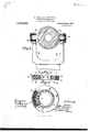
- Fig. 8 is an axial section of a particular construction of a spring ball bearing.
- Fig. 4 is a front view partly in section of this ball bearing.
- Fig. 5 is a modification.
- the pivot pin a (Fig. 1) which carries the trunnion bearings in the fork b, is supported in the frame 0 by means of the two bearings d and e, of which the lower (5 is Specification of Letters Patent.
- These sockets are slightly conical to allow for the tilting movements at the corresponding parts of the pivot pin.
- the arms of the fork b are also formed with spring ball bearings m in which the trunnions n are journaled.
- the preferred form of construction of the spring ball bearing which is shown in Figs. 3 and 4;, comprises two concentric rings 0 and 79, between which the balls 9 are placed.
- the outer ring 29 is not fixed as in the ordinary construction, but is displaceable in a casing r which has a detachable cover or section 8.
- a casing r which has a detachable cover or section 8.
- This spring is designed to give under the action of stresses normal. to the axis of the ball bearing.
- Springs of other shape can be used, but the form shown has an especial advantage on account of the perfectly symmetrical spring action on the whole circum ference of the ball bearing. It may have any required cross section, and might also be placed inside the ball bearing, as shown in Fig. 5, wherein we have shown a slight modification, the ball bearings Z and 70 being arranged within the pivot pin between the latter and the pillar.
- the ring 0 of the ball bearing is of less diameter than the opening in the casing and can therefore be moved out of parallelism with the ring 79. This permits the pin to take up a small inclination or movement about any point.
Landscapes
- Engineering & Computer Science (AREA)
- General Engineering & Computer Science (AREA)
- Rolling Contact Bearings (AREA)
Description
K. VGLLER & 0. WANINGER.
SUPPORT OF PIVOTED GUNS.
APPLICATION FILED MAR.6,1912.
1,073,061. Patented Sept. 9, 1913.
3 SHEETS-SHEET 1.
'unuu IIIIIDI'II'IIIIIIJ I m. 2 9 M 1? 9n h w M E SE w .wa m M P K. Vb'LLBR & 0. WANINGER.
I SUPPORT OF PIVO'IED GUNS.
ALPILIUATION FILED MAR. 6,1912.
K. VO'LLBR & 0. WANINGER. SUPPORT OF PIVOTED GUNS.v APPLIOATION FILED MAR. 6,1912.
1,073,061 Patented Sept. 9, 1913.
3 SHEETS-SHEET 8.
UNITED STATES PATENT OFFICE.
KARL V6LLER AND CARL WANINGER, OF DUSSELDORF, GERMANY.
SUPPORT OF PIVOTED GUNS.
To all whom it may concern Be it known that we, KARL VoLLun, a subject of the German Emperor, residing at 12 Scharnhorststrasse, Dusseldorf, Germany, and CARL I-winner, a subject of the German Emperor, residing at 128 Uerdingenstrasse, Dusseldorf, Germany, have invented certain new and useful Improvements in the Supports of Pivoted Guns; and we do hereby declare the following to be a full, clear, and exact description of the invention, such as will enable others skilled in the art to which it appertains to make and use the same.
In pivot guns the pivot pin is carried on a supporting frame, which allows the pin a certain amount of play at the upper and lower parts and the pin engages in special [bearings provided in the frame. 2 O
lVhen such guns are mounted on board ship a tilting moment is produced by the inclination of the vessel, which presses the pivot pin against the said bearings. This makes it diflicult to turn the gun in the pivot supports so as to train it as required. It has been previously proposed, to lessen the friction due'to the rubbing of the pin by arranging an upper circular ball hearing, but this still leaves the rubbing friction at the lower pivot pin bearing. The present invention obviates this drawback, by providing between the pivot frame and the pivot pin, which is journaled in the frame at the top and bottom with a certain amount of clearance, at least one spring ball bearing, so as to allow a given displacement of the pivot pin, due to the tilting moment, which may be set up. Also to avoid too much friction at the trunnions due to the tilting moment when the ship rolls, according to the invention, the trunnion bearings are also provided with annular spring ball bearings.
A construction according to the invention is represented in the accompanying drawing.
Figure 1 is a vertical section through the pivot pin bearings. Fig. 2 is a cross section through the gun barrel in the axis of the trunnions. Fig. 8 is an axial section of a particular construction of a spring ball bearing. Fig. 4 is a front view partly in section of this ball bearing. Fig. 5 is a modification.
The pivot pin a (Fig. 1) which carries the trunnion bearings in the fork b, is supported in the frame 0 by means of the two bearings d and e, of which the lower (5 is Specification of Letters Patent.
Application filed. March 6, 1912.
Patented Sept. 9, 1913. Serial No. 681,993.
clearance between the sockets and the pin.
These sockets are slightly conical to allow for the tilting movements at the corresponding parts of the pivot pin.
In order that there should be no friction at the borings it and 71 due to the tilting moments when the ship is inclined, at both places spring ball bearings and Z are inserted, which take up the thrust of the tilting moment. Only in the case when the tilting moment is so great, that it exceeds the spring resistance of the ball bearings, can such an inclination of the pivot take place, as to overstep the clearance at the sockets h and 2'. Such an increase in the tilting moment is however only likely to occur at the moment. of firing, consequently at a time, when no rotation of the pivot pin is required, while the tilting moment due to the inclination of the ship depends simply upon the distribution of the weight of the gun and can be kept within the limits suitable to the spring resistance of the ball bearing.
To prevent any friction at the trunnions due to tilting moments, the arms of the fork b are also formed with spring ball bearings m in which the trunnions n are journaled. By this formation, when the ship is inclined, the trunnions will not move with excessive friction, in the bearings and thereby render the movement difficult. The springs give on firing and the impulse is transmitted to the fork b.
The preferred form of construction of the spring ball bearing which is shown in Figs. 3 and 4;, comprises two concentric rings 0 and 79, between which the balls 9 are placed. The outer ring 29 is not fixed as in the ordinary construction, but is displaceable in a casing r which has a detachable cover or section 8. In the casing is a closely wound spiral spring t, which is held between the displaceable ring 2?, and the circumferential wall of the casing r and a retaining ring it. This spring is designed to give under the action of stresses normal. to the axis of the ball bearing. Springs of other shape can be used, but the form shown has an especial advantage on account of the perfectly symmetrical spring action on the whole circum ference of the ball bearing. It may have any required cross section, and might also be placed inside the ball bearing, as shown in Fig. 5, wherein we have shown a slight modification, the ball bearings Z and 70 being arranged within the pivot pin between the latter and the pillar.
As shown in Fig. 8 the ring 0 of the ball bearing is of less diameter than the opening in the casing and can therefore be moved out of parallelism with the ring 79. This permits the pin to take up a small inclination or movement about any point.
We claim as our invention:
1. In a pivoted gun having a depending centrallynrranged pivot member, a frame KARL voLLnn. 1A. 8.] CARL VVANINGER. [L.s.] Witnesses HELEN Noreen, A. NUFER.
Copies of this patent may be obtained for five cents each, by addressing the Commissioner of Patents, Washington, D. C.
Priority Applications (1)
| Application Number | Priority Date | Filing Date | Title |
|---|---|---|---|
| US68199312A US1073061A (en) | 1912-03-06 | 1912-03-06 | Support of pivoted guns. |
Applications Claiming Priority (1)
| Application Number | Priority Date | Filing Date | Title |
|---|---|---|---|
| US68199312A US1073061A (en) | 1912-03-06 | 1912-03-06 | Support of pivoted guns. |
Publications (1)
| Publication Number | Publication Date |
|---|---|
| US1073061A true US1073061A (en) | 1913-09-09 |
Family
ID=3141294
Family Applications (1)
| Application Number | Title | Priority Date | Filing Date |
|---|---|---|---|
| US68199312A Expired - Lifetime US1073061A (en) | 1912-03-06 | 1912-03-06 | Support of pivoted guns. |
Country Status (1)
| Country | Link |
|---|---|
| US (1) | US1073061A (en) |
Cited By (1)
| Publication number | Priority date | Publication date | Assignee | Title |
|---|---|---|---|---|
| US4819540A (en) * | 1984-10-11 | 1989-04-11 | Cadillac Gage Textron Inc. | Weapon mount useful for combat vehicle |
-
1912
- 1912-03-06 US US68199312A patent/US1073061A/en not_active Expired - Lifetime
Cited By (1)
| Publication number | Priority date | Publication date | Assignee | Title |
|---|---|---|---|---|
| US4819540A (en) * | 1984-10-11 | 1989-04-11 | Cadillac Gage Textron Inc. | Weapon mount useful for combat vehicle |
Similar Documents
| Publication | Publication Date | Title |
|---|---|---|
| SU638269A3 (en) | Blast furnace charge distributor drive | |
| US20220373296A1 (en) | Sight and compensating mechanism thereof | |
| US1073061A (en) | Support of pivoted guns. | |
| DE2921228A1 (en) | TARGET SEARCH HEAD FOR A MISSILE | |
| US2554019A (en) | Gun mount | |
| US2253119A (en) | Bearing means for shafts | |
| US825241A (en) | Apparatus for viewing and photographing the sea-bottom from the surface. | |
| US1289170A (en) | Gyroscope. | |
| US382182A (en) | nordenfelt | |
| US299218A (en) | gruson | |
| US1024424A (en) | Torpedo-launching tube. | |
| US1213579A (en) | Lookout-mast for ships. | |
| US1190187A (en) | Ordnance-mount turning on a central pivot. | |
| GB191513280A (en) | Improvements in Gyrostatic Apparatus. | |
| US3772960A (en) | Device for a sight | |
| US330638A (en) | timbt | |
| US1402407A (en) | Gun mounting | |
| US420170A (en) | Gun-carriage | |
| US3078766A (en) | Equilibrator for a gun | |
| US98595A (en) | Improvement in gun-carriages | |
| US2190332A (en) | Pivot gun | |
| US1376793A (en) | Pivot-gun | |
| US397764A (en) | vayasseur | |
| Payne | The Yerkes telescope | |
| US1041384A (en) | Gun mounting. |