US10729068B2 - Method and system for automatically controlling a position of a ground engaging tool of an agricultural implement relative to a ground surface - Google Patents
Method and system for automatically controlling a position of a ground engaging tool of an agricultural implement relative to a ground surface Download PDFInfo
- Publication number
- US10729068B2 US10729068B2 US15/830,366 US201715830366A US10729068B2 US 10729068 B2 US10729068 B2 US 10729068B2 US 201715830366 A US201715830366 A US 201715830366A US 10729068 B2 US10729068 B2 US 10729068B2
- Authority
- US
- United States
- Prior art keywords
- ground engaging
- engaging tool
- tool
- controller
- implement
- Prior art date
- Legal status (The legal status is an assumption and is not a legal conclusion. Google has not performed a legal analysis and makes no representation as to the accuracy of the status listed.)
- Active, expires
Links
Images


Classifications
-
- A—HUMAN NECESSITIES
- A01—AGRICULTURE; FORESTRY; ANIMAL HUSBANDRY; HUNTING; TRAPPING; FISHING
- A01D—HARVESTING; MOWING
- A01D41/00—Combines, i.e. harvesters or mowers combined with threshing devices
- A01D41/12—Details of combines
- A01D41/14—Mowing tables
- A01D41/141—Automatic header control
-
- A—HUMAN NECESSITIES
- A01—AGRICULTURE; FORESTRY; ANIMAL HUSBANDRY; HUNTING; TRAPPING; FISHING
- A01B—SOIL WORKING IN AGRICULTURE OR FORESTRY; PARTS, DETAILS, OR ACCESSORIES OF AGRICULTURAL MACHINES OR IMPLEMENTS, IN GENERAL
- A01B63/00—Lifting or adjusting devices or arrangements for agricultural machines or implements
- A01B63/02—Lifting or adjusting devices or arrangements for agricultural machines or implements for implements mounted on tractors
- A01B63/10—Lifting or adjusting devices or arrangements for agricultural machines or implements for implements mounted on tractors operated by hydraulic or pneumatic means
- A01B63/111—Lifting or adjusting devices or arrangements for agricultural machines or implements for implements mounted on tractors operated by hydraulic or pneumatic means regulating working depth of implements
-
- A—HUMAN NECESSITIES
- A01—AGRICULTURE; FORESTRY; ANIMAL HUSBANDRY; HUNTING; TRAPPING; FISHING
- A01B—SOIL WORKING IN AGRICULTURE OR FORESTRY; PARTS, DETAILS, OR ACCESSORIES OF AGRICULTURAL MACHINES OR IMPLEMENTS, IN GENERAL
- A01B79/00—Methods for working soil
- A01B79/005—Precision agriculture
Definitions
- the present subject matter relates generally to position control methods and systems for agricultural implements, and, more particularly, to a method and system for controlling the position of one or more ground engaging tools of an agricultural implement relative to a ground surface.
- Tillage implements typically include a plurality of ground engaging tools configured to till the soil over which the implement travels.
- the implement may include certain ground engaging tools, such as shanks, configured to penetrate the soil to a particular depth.
- the ground engaging tools may be pivotally coupled to a frame of the implement.
- Tillage implements may also include additional ground engaging tools, such as harrows configured to level or otherwise flatten any windrows or ridges in the soil and/or baskets configured to reduce the number of clods in the soil and/or firm the soil over which the implement travels.
- the positions of the various ground engaging tools may be controlled using a control system, for example a proportional-integral (“PI”) or proportional-integral-derivative (“PID”) control system.
- PI proportional-integral
- PID proportional-integral-derivative
- the control system may maintain the positions of the ground engaging tools within respective thresholds of target positions with respect to the ground surface, e.g., ground penetration depths. Delays within the control system, however, may make the system poorly suited to respond to large changes in the target position. Such large changes may be caused, for example, by an operator selecting a new target position and/or uneven ground surfaces.
- the present subject matter is directed to a method for automatically controlling a position of one or more ground engaging tools of an agricultural implement relative to a ground surface.
- the method may include monitoring a position signal indicative of a position of a ground engaging tool of the agricultural implement.
- the position signal may have a system delay time associated therewith.
- the method may include estimating an arrival time when the position of the ground engaging tool will be within a predetermined threshold of a target position based on the monitored position signal and the system delay time associated with the monitored position signal.
- the method may include adjusting the position of the ground engaging tool.
- the method may include terminating, with the one or more computing devices, the adjusting of the position of the ground engaging tool at a termination time, the termination time being based on the arrival time.
- the present subject matter is directed to a position control system for controlling a position of one or more ground engaging tools of an agricultural implement.
- the system may include a support structure, a ground engaging tool coupled to the support structure, and a tool position sensor configured to generate position signals indicative of a position of the ground engaging tool.
- the system may include at least one controller communicatively coupled to the tool position sensor.
- the at least one controller may include a processor and associated memory, and the memory may store instructions that, when executed by the processor, configure the at least one controller to perform operations.
- the operations may include monitoring the position signals, and the position signals may have a system delay time associated therewith.
- the operations may include estimating an arrival time when the error signal will be within a predetermined threshold of a target position based on the monitored position signal and the system delay time associated with the monitored position signal.
- the operations may include adjusting the position of the ground engaging tool and terminate the adjusting of the position of the ground engaging tool at a termination time. The termination time may be determined based on the arrival time.
- the present subject matter is directed to a method for automatically controlling a position of one or more ground engaging tools of an agricultural implement relative to a ground surface.
- the method may include monitoring a position signal indicative of a position of a ground engaging tool of the agricultural implement.
- the position signal may have a system delay time associated therewith.
- the method may include estimating an arrival time when the position of the ground engaging tool will be within a predetermined threshold of a target position based on the monitored position signal and the system delay time associated with the monitored position signal.
- the method may include adjusting the position of the ground engaging tool.
- the method may include determining if the position of the ground engaging tool will overshoot at least one of the target position or an upper bound of the predetermined threshold of the target position.
- the method may include, when it is determined that the position of the ground engaging tool will overshoot at least one of the target position or an upper bound of the predetermined threshold of the target position, terminating, with the one or more computing devices, the adjusting of the position of the ground engaging tool at a termination time, the termination time being based on the arrival time.
- FIG. 1 illustrates a perspective view of one embodiment of an agricultural implement coupled to a work vehicle in accordance with aspects of the present subject matter
- FIG. 2 illustrates an alternative perspective view of the agricultural implement shown in FIG. 1 in accordance with aspects of the present subject matter, particularly illustrating various ground engaging tools of the implement;
- FIG. 3 illustrates a side elevation view of another embodiment of an agricultural implement in accordance with aspects of the present subject matter, particularly illustrating the various ground engaging tools of the implement positioned relative to the ground;
- FIG. 4 illustrates a schematic view of one embodiment of a system for automatically controlling a position of one or more ground engaging tools of an agricultural implement relative to a ground surface in accordance with aspects of the present subject matter
- FIG. 5A illustrates a simplified schematic view of an example implementation of a method for automatically controlling a position of one or more ground engaging tools of an agricultural implement relative to a ground surface in accordance with aspects of the present disclosure
- FIG. 5B illustrates sample plots of several parameters over time corresponding to the example implementation illustrated in FIG. 5A in accordance with aspects of the present disclosure
- FIG. 6 illustrates a sample comparison between the position of ground engaging tool(s) controlled in accordance with aspects of the present disclosure and a conventional PID control system.
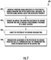
- FIG. 7 illustrates a flow diagram of one embodiment of a method for automatically controlling a position of one or more ground engaging tools of an agricultural implement relative to a ground surface in accordance with aspects of the present subject matter
- FIG. 8 illustrates a flow diagram of a control algorithm representing a specific implementation of one embodiment of a method for automatically controlling a position of one or more ground engaging tools of an agricultural implement relative to a ground surface in accordance with aspects of the present subject matter
- a tillage implement, or other agricultural implement may be moved across a field to perform an agricultural operation, such as a tilling operation.
- a control system associated with the implement may control the positions of various ground-engaging tools supported on the implement with respect to a ground surface over which the implement is moved.
- An operator may set desired operating parameters for the agricultural operations, for example, the penetration depths with respect to the ground surface of the various ground-engaging tools.
- a delay associated with the control system may prevent the control system from adequately performing large adjustments in the positions of the ground engaging tools with respect to the ground surface and/or a frame of the implement. The large adjustments may be caused, for example, by the operator changing target positions for one or more of the ground-engaging tools and/or uneven ground surfaces.
- a method for automatically controlling a position of a ground engaging tool of an implement relative to a ground surface may include monitoring a position signal indicative of a position of a ground engaging tool of the agricultural implement.
- the position signal may have a system delay time associated therewith.
- the method may include estimating an arrival time when the position of the ground engaging tool will be within a predetermined threshold of a target position based on the monitored position signal and the system delay time associated with the monitored position signal.
- the method may include adjusting the position of the ground engaging tool.
- the method may include terminating, with the one or more computing devices, the adjusting of the position of the ground engaging tool at a termination time, the termination time being based on the arrival time.
- terminating adjustment of the position of the ground engaging tool at the termination time may prevent the position of the ground engaging tool of overshooting the target position, which otherwise may be caused by the delay associated with the position signals. Additionally, this may allow the control system to be more suitably tuned to respond to large changes in the target position, as described in greater detail below.
- FIGS. 1 and 2 illustrate differing perspective views of one embodiment of an agricultural tillage implement 10 in accordance with aspects of the present subject matter.
- FIG. 1 illustrates a perspective view of the tillage implement 10 coupled to a work vehicle 12 .
- FIG. 2 illustrates a perspective view of the tillage implement 10 , particularly illustrating various components of the implement 10 .
- the implement may be any suitable type of agricultural implement.
- the tillage implement 10 may be configured to be towed across a field along a direction of travel 14 by the work vehicle 12 .
- the work vehicle 12 may be configured as an agricultural tractor having a plurality of track assemblies 16 for use in traversing the field. It should be appreciated, however, that the work vehicle 12 may be configured as any suitable work vehicle, such as a wheeled vehicle.
- the implement 10 may be coupled to the work vehicle 12 via a hitch assembly 18 or using any other suitable attachment means.
- the tillage implement 10 may include an implement frame 20 .
- the frame 20 may extend longitudinally between a forward end 22 and an aft end 24 .
- the frame 20 may also extend laterally between a first side 26 and a second side 28 .
- the frame 20 may generally include a plurality of structural frame members 30 , such as beams, bars, and/or the like, configured to support or couple to a plurality of ground engaging tools.
- a plurality of wheels may be coupled to the frame 20 , such as a set of centrally located wheels 32 and a set of front pivoting wheels 34 , to facilitate towing the implement 10 in the direction of travel 14 .
- the frame 20 may be configured to support a cultivator 36 , which may be configured to till or otherwise break the soil of a ground surface 37 over which the implement 10 travels to create a seedbed.
- the cultivator 36 may include a plurality of ground engaging tools 38 (e.g., shanks), which are pulled through the soil as the implement 10 moves across the field in the direction of travel 14 .
- the ground engaging tools 38 may be configured to be pivotally mounted to the frame 20 to allow the ground engaging tools 38 pivot out of the way of rocks or other impediments in the soil. As shown, the ground engaging tools 38 may be arranged into a plurality of ranks 40 , which are spaced apart from one another longitudinally between the forward end 22 and the aft end 24 of the frame 20 .
- the frame 20 may include one or more sections. As illustrated in FIG. 2 , for example, the frame 20 may include a main section 42 positioned centrally between the first and second sides 26 , 28 of the frame 20 . The frame 20 may also include a first wing section 44 positioned proximate to the first side 26 of the frame 20 . Similarly, the frame 20 may also include a second wing section 46 positioned proximate to the second side 28 of the frame 20 . The first and second wing sections 44 , 46 may be pivotally coupled to the main section 42 of the frame 20 .
- first and second wing sections 44 , 46 may be configured to fold up relative to the main section 42 to reduce the lateral width of the implement 10 to permit, for example, storage or transportation of the implement 10 on a road.
- the frame 20 may include any suitable number of wing sections.
- the implement 10 may also include one or more harrows 48 .
- the harrows 48 may be configured to be pivotally coupled to the frame 20 .
- the harrows 48 may include a plurality of ground engaging tools 50 , such as tines or spikes, which are configured to level or otherwise flatten any windrows or ridges in the soil created by the cultivator 36 .
- the ground engaging tools 50 may be configured to be pulled through the soil as the implement 10 moves across the field in the direction of travel 14 .
- the implement 10 may include any suitable number of harrows 48 . In fact, some embodiments of the implement 10 may not include any harrows 48 .
- the implement 10 may optionally include one or more additional ground engaging tools, such as one or more baskets or rotary firming wheels 52 .
- the baskets 52 may be configured to reduce the number of clods in the soil and/or firm the soil over which the implement 10 travels.
- each basket 52 may be configured to be pivotally coupled to one of the harrows 48 .
- the baskets 52 may be configured to be pivotally coupled to the frame 20 or any other suitable location of the implement 10 .
- the implement 10 may include any suitable number of baskets 52 . In fact, some embodiments of the implement 10 may not include any baskets 52 .
- the implement 10 may include a plurality of actuators configured to adjust or and/or control the positions of the various ground engaging tools of the implement 10 .
- at least one basket actuator 54 may be configured to adjust the position of the basket(s) 52 relative to the implement frame 20 to adjust a basket force between the basket(s) 52 and the ground surface 37 .
- At least one harrow actuator 56 may be configured to adjust the position of ground engaging tools 50 of the harrow(s) 48 relative to the implement frame 20 to adjust a harrow force between the ground engaging tools 50 and the ground surface 37 and/or a tool penetration depth.
- the tool penetration depth may be the depth below the ground surface 37 that the ground engaging tools 50 of the harrow(s) 48 extend respect to the ground surface 37 to level or otherwise flatten windrows or ridges in the soil.
- at least one cultivator actuator 58 may be configured to adjust the position of the cultivator 36 relative to the implement frame 20 to adjust a cultivator force between the ground engaging tools 38 and the ground surface and/or a tool penetration depth of the ground engaging tools 38 .
- the plurality of actuators may be configured to raise and lower the implement frame 20 and/or cultivator 36 with respect to the ground surface 37 to adjust the penetration depths of the various ground engaging tools.
- the plurality of actuators may be configured to adjust one or more local heights 60 of the implement frame 20 and/or cultivator 36 with respect to the ground surface 37 .
- the system 100 may include an implement controller 102 installed on and/or otherwise provided in operative association with the implement 10 .
- the system 100 may also include a vehicle controller 104 installed on and/or otherwise provided in operative association with the work vehicle 12 .
- the implement controller 104 may be configured to electronically control the operation of one or more components of the implement 10 , such as by electronically controlling the operation of one or more of the implement-based actuators to adjust the position(s) of the associated ground engaging tools of the implement.
- the vehicle controller 104 may generally be configured to electronically control the operation of one or more components of the work vehicle 12 .
- the implement controller 102 and vehicle controller 104 may correspond to any suitable processor-based device known in the art, such as a computing device or any suitable combination of computing devices.
- the controllers 102 , 104 may generally be configured as electronic control units (ECUs).
- the implement controller 102 may include one or more processor(s) 106 and associated memory device(s) 108 configured to perform a variety of computer-implemented functions.
- the vehicle controller 104 may also include one or more processor(s) 110 and associated memory device(s) 112 configured to perform a variety of computer-implemented functions.
- processor refers not only to integrated circuits referred to in the art as being included in a computer, but also refers to a controller, a microcontroller, a microcomputer, a programmable logic controller (PLC), an application specific integrated circuit, and other programmable circuits.
- PLC programmable logic controller
- the memory device(s) 108 , 112 may generally comprise memory element(s) including, but not limited to, a computer readable medium (e.g., random access memory (RAM)), a computer readable non-volatile medium (e.g., a flash memory), a floppy disk, a compact disc-read only memory (CD-ROM), a magneto-optical disk (MOD), a digital versatile disc (DVD) and/or other suitable memory elements.
- a computer readable medium e.g., random access memory (RAM)
- a computer readable non-volatile medium e.g., a flash memory
- CD-ROM compact disc-read only memory
- MOD magneto-optical disk
- DVD digital versatile disc
- Such memory device(s) 108 , 112 may generally be configured to store suitable computer-readable instructions that, when implemented by the processor(s), configure the vehicle controller 104 and/or implement controller 102 to perform various computer-implemented functions, such as one or more aspects of the method 400 and/or algorithm 500 described below with reference to FIGS. 7 and 8 .
- the vehicle controller 104 and/or implement controller 102 may also include various other suitable components, such as a communications circuit or module, one or more input/output channels, a data/control bus and/or the like.
- the system 100 may include at least one tool position sensor 114 configured to directly or indirectly detect the position of at least one of the ground engaging tools of the implement 10 relative to the ground surface 37 .
- the tool position sensor(s) 114 may be communicatively connected with the implement controller 102 .
- the position sensor(s) 114 may include a basket position sensor(s), harrow position sensor(s), cultivator position sensor(s) and/or any other suitable tool tools position sensor(s) configured to sense the position of any ground engaging tools supported on the implement 110 .
- the tool position sensor(s) 114 may be configured to sense, for example, the distance that the respective ground engaging tools extend from the implement frame 20 and/or cultivator 36 .
- the tool position sensor(s) 114 may also be configured to sense the distance(s) that the implement frame 20 and/or cultivator 36 are disposed above the ground surface 37 such that the positions of the ground engaging tools (e.g., ground penetration distances) may be indirectly sensed or calculated relative to the ground surface 37 .
- the tool position sensors 114 may be configured to sense the force exerted between the respective ground engaging tools and the ground surface 37 .
- the implement controller 102 and/or vehicle controller 104 may then be configured to calculate penetration depths and/or relative positions of the various ground engaging tools with respect to the ground surface 37 based on the monitored force(s).
- the tool position sensor(s) 114 may include one or more inclinometers to sense fore/aft inclination angles of the implement frame 20 and/or cultivator 36 , thereby providing an indication of the position(s) of one or more sets of the ground engaging tools.
- tool position sensor(s) 114 may be configured to sense various local heights 60 of the implement frame 20 and/or cultivator 36 with respect to the ground surface 37 such that the fore/aft inclination angle(s) of the implement frame 20 and/or cultivator 36 may be calculated therefrom.
- the control system 100 may include one or more control valves 116 configured to regulate the supply of fluid (e.g., hydraulic fluid or air) to one or more of actuator(s) 118 configured to control the positions of the ground engaging tools of the implement 10 .
- the vehicle controller 104 may be communicatively coupled with the valve(s) 116 .
- the valve(s) 116 may be fluidly connected with the actuator(s) 118 through a plurality of hydraulic lines 119 .
- the valve(s) 116 are illustrated and described as located on the work vehicle 12 (e.g., an ISOBUS Class 3 configuration), in other embodiments, the valve(s) may be located on the implement 10 (e.g., an ISOBUS Class 2 configuration).
- the vehicle controller 104 may be communicatively coupled with the valves 116 through a communication connection (e.g., a hard-wired connection or wireless connection).
- valve(s) 116 may be communicatively coupled with the implement controller 102 , instead of the vehicle controller 12 .
- the implement controller 102 may transmit the position signals to the vehicle controller 104
- the vehicle controller 104 may transmit instructions to the implement controller 102 to control the positions of the ground engaging tools.
- the actuators 118 may include the basket actuator(s), harrow actuator(s), and/or the cultivator actuator(s), for example.
- the system 100 may be configured to adjust ground forces and/or penetration depths associated with the various ground engaging tools connected with the implement 10 .
- the system 100 may be configured to adjust the harrow force, basket force, cultivator force, the tool penetration depth, and/or the like.
- the control system 100 may be configured to control the actuators 118 based in part on signals received from the tool position sensor(s) 114 , as explained in greater detail below.
- the vehicle controller 104 may be communicatively coupled with one or more input devices 120 .
- the input device(s) 120 may include a keyboard and/or touchscreen, for example.
- An operator of the work vehicle 12 may input commands or other information using the input device(s) 120 .
- the operator may input a desired operating parameter for an agricultural operation, such a tilling operation.
- the operator may input a target position (e.g., desired penetration depth and/or ground force) for one of more of the ground engaging tool associated with the implement 10 .
- the vehicle controller 104 and the implement controller 102 may communicate with each other via any suitable communications protocol.
- an ISOBus Class 3 (ISO11783) interface may be utilized to provide a standard communications protocol between the controllers.
- a proprietary communications protocol may be utilized for communications between the work vehicle controller 104 and the implement controller 102 .
- the vehicle controller 104 and implement controller 102 may wirelessly communicate.
- the controllers 102 , 104 may include wireless communication interfaces configured to transmit and/or receive data via any suitable network, such as a local wireless network using any suitable wireless communications protocol (e.g., WiFi, Bluetooth, and/or the like) and/or a broader network, such as a wide-area network (WAN), using any suitable communications protocol (e.g., TCP/IP, HTTP, SMTP, FTP).
- any suitable wireless communications protocol e.g., WiFi, Bluetooth, and/or the like
- WAN wide-area network
- any suitable communications protocol e.g., TCP/IP, HTTP, SMTP, FTP.
- the vehicle controller 104 may transmit target position signals 121 (e.g., desired penetration depth and/or ground force) to the implement controller 102 .
- the implement controller 102 may receive position signals from the tool position sensor(s) 114 and transmit adjustment signals 124 to the vehicle controller 104 .
- the adjustment signals 124 may instruct the vehicle controller 102 to adjust the position(s) of the ground engaging tool(s) using the valve(s) 116 to regulate the supply of fluid (e.g., hydraulic fluid or air) through the hydraulic lines 119 to the actuator(s) 118 .
- fluid e.g., hydraulic fluid or air
- a system delay time associated with the position signal may be the total delay time of the system.
- Various sources may contribute to the system delay time.
- the transmissions of the adjustment signals 124 and/or the supply of fluid through the hydraulic line 119 may have associated delay times.
- an adjustment signal delay time may be caused by a lag in the implement controller 102 transmitting the adjustment signals 124 to the vehicle controller 104 , the vehicle controller 104 decoding the adjustment signals 124 , the vehicle controller 104 reacting to the adjustment signals 124 , and/or the like.
- a hydraulic delay time may be caused by a lag in the vehicle controller 104 controlling the valve(s) 116 and/or the flow of fluid through the hydraulic lines 119 to the actuators 118 .
- communications delay between the controllers 102 , 104 may be caused by disparate system refresh rates.
- the system delay time may also include a delay resulting from the momentum associated with the ground engaging tool and/or support structure. In other words, accelerating or decelerating the tool and/or support structure may effectively create a delay component or reduce the responsiveness of the system.
- the systems and methods disclosed herein may be used to counteract such a delay.
- the system delay time may be measured, for example, as part of a system calibration process.
- the delay time may be measured by inputting a command signal (e.g., a step command to change the position of the implement from a first position to a second position).
- the position signal may be compared with the command signal, for example, during a time interval in which the position of the implement is adjusted as a result of the command signal. This comparison may be used to determine the delay time.
- the system calibration process may be performed manually (e.g., by an operator of the work vehicle 12 ).
- the system calibration process may be performed automatically.
- the control system 100 may be configured to automatically transmit the command signal and measure the delay time.
- the control system 100 may be configured to automatically measure the delay time periodically (e.g., monthly, weekly, etc.).
- a single controller (e.g., the vehicle controller 104 or implement controller 102 ) may be configured to monitor the tool position sensors 114 and control the actuators 118 without using a second controller.
- the single controller could be located in any suitable location.
- the methods disclosed herein may be implemented with one or more controllers that are separate from any existing vehicle controller(s) 104 or implement controller(s) 102 .
- the system 100 described herein is merely illustrative. The methods disclosed herein may be implemented with any suitable system having a delay of any type.
- the system 100 may have any suitable configuration.
- the tool position sensors 114 may be directly communicatively coupled with the vehicle controller 104 .
- a delay may still be associated with system 100 .
- the delay may be caused by internal processing, sensor lag, and/or the like.
- the methods and systems disclosed herein may provide improved control for systems having associated delays.
- FIGS. 5A and 5B illustrate an example implementation 200 of a method for automatically controlling a position of one or more ground engaging tools of an agricultural implement relative to a ground surface 37 in accordance with aspects of the present disclosure.
- FIG. 5A illustrates a simplified schematic view of the example implementation 200 in which a controller controls the operation of a system using a feedback loop.
- a commanded target position 201 is input, and an error signal is calculated.
- the controller generates the output command 202 based on the error signal, which may be calculated as the difference between the commanded target position 201 and a monitored tool position 204 .
- the system adjusts the tool position based on the monitored tool position 202 .
- FIG. 5B plots these three variables against time on the horizontal axis.
- the top plot illustrates the commanded target position 201 .
- the middle plot illustrates the output command 202 of the control system 100 (e.g., the adjustment signals 124 transmitted by the implement controller 102 to the vehicle controller 104 ).
- the bottom plot illustrates the monitored tool position 204 based on the corresponding position signals (e.g., received by the implement controller 102 from the tool position sensor(s) 114 ).
- the system delay time (illustrated by arrow 205 ) may exist between the output command 202 and the monitored tool position 204 as a result of at least one of a measurement delay and/or a response delay associated with the control system 100 .
- the commanded target position 201 of the ground engaging tool may change from an initial value (zero in this example) to a new value (illustrated by dotted line 201 after to).
- the commanded target position 201 of the ground engaging tool may have an equivalent target position value 208 , (illustrated on the bottom chart).
- the output command 202 may be adjusted such that the tool position is adjusted towards the target position. Because of the system delay time 205 , however, the actual position of the implement may not change during the first time period 210 because of the response delay associated with the control system 100 . Thus, the monitored tool position 204 may not show movement of the ground engaging tool during the first time period 210 . At a first time, t 1 , the ground engaging tool may be begin to move, and the monitored tool position 204 may begin to indicate such movement, as illustrated in the bottom chart by an increase in the monitored tool position 204 .
- the control system 100 may estimate an arrival time (indicated by t arrival ) when the actual position of the ground engaging tool will be within a calculated predetermined threshold 214 of the target position value 208 . In some embodiments, this estimation may be based on the monitored tool position 204 during the second period 212 and the associated system delay time 205 . For example, in some embodiments, the control system 100 may assume that the once the command is given to stop moving the ground engaging tool, the system delay time 205 must pass before the ground engaging tool stops in response. In some embodiments, the control system 100 may calculate an average velocity of the ground engaging tool based on the rate of change of the monitored tool position 204 during the second time period 212 .
- control system 100 may assume that the ground engaging tool has been moving at the average velocity since the initial time, t 0 .
- more complicated projection algorithms may be used, for example, based on experimental data, the response characteristics of the hydraulic system, and/or the like.
- the system 100 may calculate a termination time (indicated by t term in FIG. 5B ).
- the system (for example the implement controller 102 ) may attempt to stop adjusting the position of the ground engaging tool at the termination time, t term .
- the control system 100 may attempt to stop the movement of the position of the ground engaging tool towards the target position before the ground engaging tool actually reaches the target position so that after the system delay time 205 passes and the control system 100 actually stops adjusting the position of the ground engaging tool, the position of the ground engaging tool may be within the predetermined threshold 214 of the target position value 208 . This is illustrated by the dotted portion of line 202 in the middle plot dropping rapidly from t term to t arrival .
- the output command 202 may not drop instantaneously to zero at t term to prevent excessive acceleration or jerk.
- the decrease in the output command 202 from t term to t arrival may be the result of any suitable control algorithm that accounts for the momentum of the tool.
- the output command 202 may drop almost instantaneously to zero at t term .
- such a near instantaneous drop may be appropriate when the methods disclosed herein are implemented to control a parameter having small or no associated momentum (e.g., a force parameter).
- an asymmetric threshold region may be defined about the target position.
- a first predetermined threshold may define a lower bound which is below (e.g., less than) than the target position value 208
- a second predetermined threshold may define an upper bound which is above (e.g., greater than) the target position value 208 .
- the locations of the upper bound and lower bound may depend on whether the target position value 208 is greater than or less than the monitored tool position 204 .
- the disclosed methods may be used to control the position of the ground engaging tools relative to the ground surface 37 .
- doing so may involve adjusting the position of the associated support structure, such as the implement frame 20 and/or cultivator 36 , relative to the ground surface 37 .
- the actuators 118 may be used to adjust the local heights 60 and/or fore-aft angle of the implement frame 20 and/or cultivator 36 .
- adjusting the position of the ground engaging tools relative to the ground surface 37 may involve moving a relatively large mass, e.g., the implement frame 20 and/or cultivator 36 . Accordingly, the mass associated with the tools and their corresponding support structure may be significant, in some embodiments.
- the termination time may be selected to compensate for the momentum of the associated support structure (e.g., the implement frame 20 and/or cultivator 36 ). In other embodiments, the termination time may not compensate for any momentum, and, accordingly, the termination time may equal the arrival time. This may be appropriate where the disclosed methods are used to control a tool ground force or down pressure, for example. In such an instance, compensating for the momentum of the ground engaging tool may not be appropriate.
- FIG. 6 illustrates a time-varying sample comparison 300 between the actual position 302 of a ground engaging tool controlled in accordance with aspects of the present disclosure and a conventional control system (e.g., a PID control system).
- a conventional system PID control system may not be suited to accommodate large changes in the target position of the ground engaging tool when there is a system delay time, as discussed above.
- such a conventional control system may result in the actual position of the ground engaging tool overshooting (for example as illustrated by dotted line 304 ) or responding undesirably slowly (for example as illustrated by dotted line 306 ).
- a ground engaging tool controlled in accordance aspects of the present disclosure may rapidly approach a target position 308 despite such a system delay time.
- the control system may stop actively adjusting the position of the ground engaging tool to prevent overshoot despite the delay associated with the system.
- the termination time may be before the arrival time to compensate for the momentum of the ground engaging tool and/or support structure. Such momentum may carry the ground engaging tool within the predetermined threshold 310 of the target position 308 .
- FIG. 7 a flow diagram of one embodiment of a method 400 for automatically controlling a position of one or more ground engaging tools of an implement relative to a ground surface is illustrated in accordance with aspects of the present subject matter.
- the method 400 will be described herein with reference to the implement 10 described above with reference to FIGS. 1-3 and the system 100 described above with reference to FIG. 4 .
- the disclosed method 200 may generally be utilized to control the position of any suitable ground engaging tools relative to a support structure, such as an implement frame, cultivator, harvester, and/or the like.
- FIG. 7 depicts steps performed in a particular order for purposes of illustration and discussion, the methods discussed herein are not limited to any particular order or arrangement.
- steps of the methods disclosed herein can be omitted, rearranged, combined, and/or adapted in various ways without deviating from the scope of the present disclosure.
- the method 400 may include, at ( 402 ), monitoring a position signal indicative of a position of a ground engaging tool of the implement.
- the position signal may have a delay time associated therewith.
- the system delay time may include a controller response delay between the implement controller 102 transmitting the adjustment signals 124 and the vehicle controller 104 responding to the adjustment signals 124 , as discussed above with reference to FIG. 4 .
- the method 400 may include, at ( 404 ), estimating an arrival time when the position of the ground engaging tool will be within a predetermined threshold of a target position. For example, in some embodiments, the estimation may be based on the monitored position signal and associated delay time. For instance, in some embodiments, because of a system delay time associated with the system 100 the ground engaging tool may not immediately stop moving upon a command to do so. Instead, for the first time period, the implement position (and monitored position signal) may remain substantially unchanged. After the delay time has passed, the implement position (and monitored position signal) may begin changing during a second time period. The implement controller 102 may be configured to estimate the arrival time based on a portion of the position signal 122 during the second time period.
- the implement controller 102 may be configured to calculate an average velocity of the ground engaging tool based on the position signal.
- the system 100 e.g., the implement controller 102 , the vehicle controller 104 , or a controller that is distinct from each of the implement controller 102 and vehicle controller 104
- the system 100 may be configured to calculate the arrival time by assuming that the ground engaging tool will continue to move at the average velocity for the system delay time.
- more complicated projection algorithms may be used, for example, based on experimental data, the response characteristics of the hydraulic system, and/or the like.
- the method 400 may include, at ( 406 ), adjusting the position of the ground engaging tool.
- the control system 100 may calculate an error signal based on a comparison between the monitored position of the ground engaging tool and a target position. The position of the ground engaging tool may be adjusted based on the error signal. In other embodiments, however, the control system may adjust the position of the ground engaging tool using any suitable method (e.g., closed-loop PI, closed-loop PID, open-loop, etc.)
- the method 400 may include, at ( 408 ), terminating the adjustment of the position of the ground engaging tool at a termination time based on the arrival time.
- the control system 100 may attempt to cease active adjustment of the position of the ground engaging tool before the ground engaging tool actually reaches the target position so that once the system delay time passes and the control system 100 actually stops adjusting the position of the ground engaging tool towards the target position, the position of the ground engaging tool is within the predetermined threshold of the target position.
- the output command signal of the control system 100 may rapidly drop starting at the termination time. For instance, the output command signal my decrease to zero between the termination time and the arrival time.
- the control system 100 may select the termination time based on the arrival time such that once the system delay time passes and the control system 100 actually stops adjusting the position of the ground engaging tool, the ground engaging tool is within the predetermined threshold of the target position.
- the termination time may be earlier than in the previous example to additionally account for the momentum of the ground engaging tool and/or the associated support structure (e.g., the implement frame 20 ) such that the momentum carries the tool to within the predetermined threshold of the target position after the control system 100 actually stops adjusting the position of the ground engaging tool.
- the implement controller 102 may instruct the vehicle controller 104 to stop adjusting the position of the ground engaging tool using the valve(s) 116 .
- control system 100 may not actively adjust the position of the ground engaging tool for a predetermined time period (e.g., until t arrival or until the delay time has passed). Then the control system 100 may resume controlling the position of the ground engaging tool using any suitable method such a closed control loop, e.g., PI or PID control loop.
- a closed control loop e.g., PI or PID control loop.
- FIG. 8 a flow diagram of another embodiment of a method 500 for automatically controlling a position of one or more ground engaging tools of an implement relative to a ground surface is illustrated in accordance with aspects of the present subject matter.
- the method 500 will be described herein with reference to the implement 10 described above with reference to FIGS. 1-3 and the system 100 described above with reference to FIG. 4 .
- the disclosed method 500 may generally be utilized to control the position of any suitable ground engaging tools relative to a support structure, such as an implement frame, cultivator, harvester, and/or the like.
- FIG. 8 depicts steps performed in a particular order for purposes of illustration and discussion, the methods discussed herein are not limited to any particular order or arrangement.
- steps of the methods disclosed herein can be omitted, rearranged, combined, and/or adapted in various ways without deviating from the scope of the present disclosure.
- the method 500 may include, at ( 502 ), may include monitoring a position signal indicative of a position of a ground engaging tool, for example as explained with reference to FIG. 7 .
- the method 500 may include, at ( 504 ), estimating an arrival time when the position of the ground engaging tool will be within a predetermined threshold of a target position, for example as explained above with reference to FIG. 7 .
- the method 500 may include, at ( 506 ), adjusting the position of the ground engaging tool, for example as explained above with reference to FIG. 7 .
- the method 500 may include, at ( 508 ), predicting whether overshoot protection is needed.
- the control system 100 may predict whether the ground engaging tool, absent preventative action, would overshoot the target position and/or an upper bound of a predetermined threshold 214 of the target position value 208 .
- the control system 100 may compare the arrival time with the system delay time associated with the position signal.
- the control system 100 may compare the average velocity of the ground engaging tool (e.g., during the second time period 212 explained with reference to FIG. 5B ) to the system delay time.
- the control system 100 may determine if overshoot protection is needed based on at least one of the system delay time, the mass of the ground engaging tool and/or support structure, response characteristics of the hydraulic system, or response characteristics of the control system 100 .
- the method 500 may include at ( 510 ), when it is determined that overshoot protection is needed, terminating, with the one or more computing devices, adjustment of the position of the ground engaging tool at a termination time.
- the control system 100 may stop actively controlling the position of the ground engaging tool at the termination time.
- the termination time may be based on the arrival time. In some embodiments, the termination time may be before the arrival time to compensate for the momentum of the ground engaging tool and/or support structure.
- the control system 100 may not resume actively adjusting the position of the ground engaging tool unless the position of the ground engaging tool exceeds a predetermined error band about the target position.
- the predetermined error band may be the same as the predetermined threshold 214 discussed above with reference to FIG. 5B . In other embodiments, however, the predetermined error band may be different than the predetermined threshold 214 . For example, the predetermined error band may be larger (e.g., encompass a greater range of positions) than the predetermined threshold 214 . Additionally, the predetermined error band may be symmetric or asymmetric about the target position.
- control system 100 may not resume actively adjusting the position of the ground engaging tool for a predetermined time period (e.g., until t arrival or until the delay time has passed). After the predetermined time period has passed, the control system 100 may, at ( 502 )-( 506 ), resume controlling the position of the ground engaging tool using any suitable method such a closed control loop, e.g., PI or PID control loop, etc.
- a closed control loop e.g., PI or PID control loop, etc.
- the method 500 may include multiple control loops and terminating adjusting the tool position at the termination time may include stopping one or more of the multiple control loops.
- the control system 100 may continue to make minor adjustments to the tool position.
- the method 500 may return to monitoring the position signal, at ( 502 ).
- a fine tuning PI or PID control loop may continuously adjust the position of the ground engaging tool, even immediately after the control system, at ( 510 ), stops adjusting the position of the ground engaging tool.
- terminating the adjustment of the position of the ground engaging tool may include stopping one control loop (but not necessarily all control loops) configured to adjust the position of the ground engaging tool.
- multiple control loops may be selectively engaged and disengaged.
- the control system 100 may be configured to implement a first control loop to adjust the position of the ground engaging tool.
- the control system 100 may also be configured to detect when the error signal exceeds a predetermined limit. When it is detected that the error signal exceeds the predetermined limit, the control system 100 may engage a second control loop configured to rapidly adjust the position of the ground engaging tool towards the target position such that the error signal is reduced.
- terminating adjusting the tool position, at ( 510 ) may include terminating the second control loop but not the first control loop.
- the first control loop may continue to make minor adjustments to the position of the ground engaging tool.
- the disclosed methods and systems may be used to selectively engage and disengage a second control loop configured to quickly adjust the position of the ground engaging tool to the target position.
- the second control loop may be configured as an open-loop system, for example.
Landscapes
- Life Sciences & Earth Sciences (AREA)
- Environmental Sciences (AREA)
- Engineering & Computer Science (AREA)
- Mechanical Engineering (AREA)
- Soil Sciences (AREA)
- Lifting Devices For Agricultural Implements (AREA)
Abstract
Description
Claims (14)
Priority Applications (1)
| Application Number | Priority Date | Filing Date | Title |
|---|---|---|---|
| US15/830,366 US10729068B2 (en) | 2017-12-04 | 2017-12-04 | Method and system for automatically controlling a position of a ground engaging tool of an agricultural implement relative to a ground surface |
Applications Claiming Priority (1)
| Application Number | Priority Date | Filing Date | Title |
|---|---|---|---|
| US15/830,366 US10729068B2 (en) | 2017-12-04 | 2017-12-04 | Method and system for automatically controlling a position of a ground engaging tool of an agricultural implement relative to a ground surface |
Publications (2)
| Publication Number | Publication Date |
|---|---|
| US20190166762A1 US20190166762A1 (en) | 2019-06-06 |
| US10729068B2 true US10729068B2 (en) | 2020-08-04 |
Family
ID=66657569
Family Applications (1)
| Application Number | Title | Priority Date | Filing Date |
|---|---|---|---|
| US15/830,366 Active 2038-10-09 US10729068B2 (en) | 2017-12-04 | 2017-12-04 | Method and system for automatically controlling a position of a ground engaging tool of an agricultural implement relative to a ground surface |
Country Status (1)
| Country | Link |
|---|---|
| US (1) | US10729068B2 (en) |
Cited By (3)
| Publication number | Priority date | Publication date | Assignee | Title |
|---|---|---|---|---|
| US20210243935A1 (en) * | 2016-03-02 | 2021-08-12 | Deere & Company | Hydraulic control system of an implement for a work machine and method thereof |
| US11419254B2 (en) * | 2019-10-28 | 2022-08-23 | Cnh Industrial Canada, Ltd. | System and method for detecting levelness of tools of a tillage implement based on tool loading |
| US12262656B2 (en) | 2021-03-29 | 2025-04-01 | Cnh Industrial America Llc | System and method for detecting material accumulation relative to basket assemblies of an agricultural implement |
Families Citing this family (10)
| Publication number | Priority date | Publication date | Assignee | Title |
|---|---|---|---|---|
| US10561052B2 (en) * | 2017-04-25 | 2020-02-18 | Cnh Industrial Canada, Ltd. | Automatic fore/aft leveling trim function in a towable tillage implement |
| JP6703021B2 (en) * | 2018-02-20 | 2020-06-03 | ファナック株式会社 | Servo control device |
| JP7107771B2 (en) | 2018-06-29 | 2022-07-27 | 株式会社小松製作所 | Working machines and systems containing working machines |
| JP7266371B2 (en) * | 2018-06-29 | 2023-04-28 | 株式会社小松製作所 | Working machines and systems containing working machines |
| US10939604B2 (en) * | 2018-10-01 | 2021-03-09 | Deere & Company | Multi-sensor tool height control for ground engaging tools |
| EP3965544B1 (en) | 2019-05-10 | 2024-11-27 | Great Plains Manufacturing, Inc. | Control system for agricultural implements and method |
| US12052941B2 (en) * | 2019-12-19 | 2024-08-06 | Cnh Industrial America Llc | System and method for calibrating tool depth of an agricultural implement based on frame position |
| US11758846B2 (en) * | 2019-12-23 | 2023-09-19 | Cnh Industrial America Llc | Header control system to adjust a header of a harvester based on sensor information |
| US11822339B2 (en) * | 2021-06-30 | 2023-11-21 | Deere & Company | Predictive technique for dispensing product from tractor tool |
| US20240172580A1 (en) * | 2022-11-30 | 2024-05-30 | Cnh Industrial America Llc | System and method for automatically leveling an agricultural implement using forward-looking sensor data |
Citations (14)
| Publication number | Priority date | Publication date | Assignee | Title |
|---|---|---|---|---|
| US4617902A (en) | 1983-12-09 | 1986-10-21 | Diesel Kiki Co., Ltd. | Apparatus for controlling fuel injection timing of fuel injection apparatus |
| US5229699A (en) | 1991-10-15 | 1993-07-20 | Industrial Technology Research Institute | Method and an apparatus for PID controller tuning |
| US5355305A (en) | 1992-10-29 | 1994-10-11 | Johnson Service Company | Pattern recognition adaptive controller |
| US5493798A (en) * | 1994-06-15 | 1996-02-27 | Caterpillar Inc. | Teaching automatic excavation control system and method |
| US5653210A (en) | 1993-03-17 | 1997-08-05 | Robert Bosch Gmbh | Method and device for the open-loop and/or closed loop control of a final controlling element |
| US6127793A (en) | 1997-08-07 | 2000-10-03 | Dr. Johannes Heidenhain Gmbh | Method and circuit arrangement for detecting optimal controller parameters for speed control |
| KR20070043071A (en) | 2005-10-20 | 2007-04-25 | 두산인프라코어 주식회사 | Gain Tuning Method of Proportional-Integral Controller |
| US20070253308A1 (en) | 2004-10-05 | 2007-11-01 | Koninklijke Philips Electronics, N.V. | Device Comprising a Feedback Control Loop for a Signal of an Optical Pickup |
| US7640078B2 (en) | 2006-07-05 | 2009-12-29 | Advanced Energy Industries, Inc. | Multi-mode control algorithm |
| US20120186504A1 (en) * | 2011-01-21 | 2012-07-26 | Cnh Canada Ltd. | System and method for coordinating product delivery with ground engaging tool position |
| US20140144233A1 (en) | 2012-11-26 | 2014-05-29 | Samsung Electro-Mechanics Co., Ltd. | Apparatus and method for automatic gain control of sensor, and sensor apparatus |
| US8840118B1 (en) | 2013-03-15 | 2014-09-23 | Levant Power Corporation | Active suspension with on-demand energy flow |
| US20150323912A1 (en) | 2014-05-08 | 2015-11-12 | King Fahd University Of Petroleum And Minerals | Closed loop pi/pid controller tuning method for stable and integrating process with time delay |
| US20190032305A1 (en) * | 2017-07-31 | 2019-01-31 | Deere & Company | Work machines and methods and systems to control and determine a position of an associated implement |
-
2017
- 2017-12-04 US US15/830,366 patent/US10729068B2/en active Active
Patent Citations (14)
| Publication number | Priority date | Publication date | Assignee | Title |
|---|---|---|---|---|
| US4617902A (en) | 1983-12-09 | 1986-10-21 | Diesel Kiki Co., Ltd. | Apparatus for controlling fuel injection timing of fuel injection apparatus |
| US5229699A (en) | 1991-10-15 | 1993-07-20 | Industrial Technology Research Institute | Method and an apparatus for PID controller tuning |
| US5355305A (en) | 1992-10-29 | 1994-10-11 | Johnson Service Company | Pattern recognition adaptive controller |
| US5653210A (en) | 1993-03-17 | 1997-08-05 | Robert Bosch Gmbh | Method and device for the open-loop and/or closed loop control of a final controlling element |
| US5493798A (en) * | 1994-06-15 | 1996-02-27 | Caterpillar Inc. | Teaching automatic excavation control system and method |
| US6127793A (en) | 1997-08-07 | 2000-10-03 | Dr. Johannes Heidenhain Gmbh | Method and circuit arrangement for detecting optimal controller parameters for speed control |
| US20070253308A1 (en) | 2004-10-05 | 2007-11-01 | Koninklijke Philips Electronics, N.V. | Device Comprising a Feedback Control Loop for a Signal of an Optical Pickup |
| KR20070043071A (en) | 2005-10-20 | 2007-04-25 | 두산인프라코어 주식회사 | Gain Tuning Method of Proportional-Integral Controller |
| US7640078B2 (en) | 2006-07-05 | 2009-12-29 | Advanced Energy Industries, Inc. | Multi-mode control algorithm |
| US20120186504A1 (en) * | 2011-01-21 | 2012-07-26 | Cnh Canada Ltd. | System and method for coordinating product delivery with ground engaging tool position |
| US20140144233A1 (en) | 2012-11-26 | 2014-05-29 | Samsung Electro-Mechanics Co., Ltd. | Apparatus and method for automatic gain control of sensor, and sensor apparatus |
| US8840118B1 (en) | 2013-03-15 | 2014-09-23 | Levant Power Corporation | Active suspension with on-demand energy flow |
| US20150323912A1 (en) | 2014-05-08 | 2015-11-12 | King Fahd University Of Petroleum And Minerals | Closed loop pi/pid controller tuning method for stable and integrating process with time delay |
| US20190032305A1 (en) * | 2017-07-31 | 2019-01-31 | Deere & Company | Work machines and methods and systems to control and determine a position of an associated implement |
Non-Patent Citations (1)
| Title |
|---|
| Sahaj Saxena and Yogesh V. Hote Internal Model Control Based PID Tuning Using First-Order Filter Dated Jul. 24, 2017 (3 pages). |
Cited By (4)
| Publication number | Priority date | Publication date | Assignee | Title |
|---|---|---|---|---|
| US20210243935A1 (en) * | 2016-03-02 | 2021-08-12 | Deere & Company | Hydraulic control system of an implement for a work machine and method thereof |
| US11930729B2 (en) * | 2016-03-02 | 2024-03-19 | Deere & Company | Hydraulic control system of an implement for a work machine and method thereof |
| US11419254B2 (en) * | 2019-10-28 | 2022-08-23 | Cnh Industrial Canada, Ltd. | System and method for detecting levelness of tools of a tillage implement based on tool loading |
| US12262656B2 (en) | 2021-03-29 | 2025-04-01 | Cnh Industrial America Llc | System and method for detecting material accumulation relative to basket assemblies of an agricultural implement |
Also Published As
| Publication number | Publication date |
|---|---|
| US20190166762A1 (en) | 2019-06-06 |
Similar Documents
| Publication | Publication Date | Title |
|---|---|---|
| US10729068B2 (en) | Method and system for automatically controlling a position of a ground engaging tool of an agricultural implement relative to a ground surface | |
| US10750656B2 (en) | System and method for monitoring the frame levelness of an agricultural implement | |
| US10838432B2 (en) | System and method for monitoring frame levelness of an agricultural implement | |
| EP3400764B1 (en) | System and method for detecting ground engaging tool float for an agricultural implement | |
| US11716920B2 (en) | Residue management based on topography by an agricultural tillage implement | |
| US10752237B2 (en) | System and method for automatically leveling an agricultural implement | |
| US11064645B2 (en) | System and method for controlling operation of a work vehicle towing an agricultural implement | |
| EP3815480B1 (en) | System and method for detecting tool plugging of an agricultural implement based on residue differential | |
| EP3403478B1 (en) | System and method for monitoring soil conditions within a field | |
| US11696523B2 (en) | System and method for hydraulically leveling a multi-wing agricultural implement | |
| EP3319411B1 (en) | Agricultural implement and method of controlling an agricultural implement | |
| US20210045278A1 (en) | System and method for detecting a plug of a tool of a tillage implement | |
| US20190343032A1 (en) | System and method for controlling the operation of an agricultural implement being towed by a work vehicle | |
| US20190320574A1 (en) | System for creating soil compaction maps and associated methods for controlling the operation of a tillage implement | |
| US11624829B2 (en) | System and method for determining soil clod size distribution using spectral analysis | |
| US12075721B2 (en) | Systems and methods for downforce control for an implement | |
| EP3788854A1 (en) | Method of controlling tilt of an agricultural implement and control system for such | |
| US20180279542A1 (en) | Seedbed condition monitoring system with a seedbed surface detection assembly | |
| US11039563B2 (en) | System for monitoring the condition of a seedbed within a field with a seedbed floor detection assembly | |
| US20240044346A1 (en) | Hydraulic cylinder position control for lifting and lowering towed implements | |
| US20180279541A1 (en) | Seedbed condition monitoring system when performing field operations | |
| Liu et al. | Development and experimental validation of a system for agricultural grain unloading-on-the-go | |
| US10356972B2 (en) | System and method for reducing variations in the penetration depths of ground-engaging tools of an agricultural implement based on monitored tire pressures | |
| EP4124224B1 (en) | Method of reactively controlling ground following of a row unit of an agricultural machine | |
| US20240268249A1 (en) | Agricultural system and method for monitoring yaw of towed agricultural implements |
Legal Events
| Date | Code | Title | Description |
|---|---|---|---|
| AS | Assignment |
Owner name: CNH INDUSTRIAL AMERICA LLC, PENNSYLVANIA Free format text: ASSIGNMENT OF ASSIGNORS INTEREST;ASSIGNORS:WU, DUQIANG;SINGH, ADITYA;GULATI, NAVNEET;AND OTHERS;REEL/FRAME:044287/0257 Effective date: 20171130 |
|
| FEPP | Fee payment procedure |
Free format text: ENTITY STATUS SET TO UNDISCOUNTED (ORIGINAL EVENT CODE: BIG.); ENTITY STATUS OF PATENT OWNER: LARGE ENTITY |
|
| STPP | Information on status: patent application and granting procedure in general |
Free format text: DOCKETED NEW CASE - READY FOR EXAMINATION |
|
| STPP | Information on status: patent application and granting procedure in general |
Free format text: NON FINAL ACTION MAILED |
|
| STPP | Information on status: patent application and granting procedure in general |
Free format text: NOTICE OF ALLOWANCE MAILED -- APPLICATION RECEIVED IN OFFICE OF PUBLICATIONS |
|
| STPP | Information on status: patent application and granting procedure in general |
Free format text: PUBLICATIONS -- ISSUE FEE PAYMENT VERIFIED |
|
| STCF | Information on status: patent grant |
Free format text: PATENTED CASE |
|
| AS | Assignment |
Owner name: BLUE LEAF I.P., INC., DELAWARE Free format text: ASSIGNMENT OF ASSIGNORS INTEREST;ASSIGNOR:CNH INDUSTRIAL AMERICA LLC;REEL/FRAME:054302/0368 Effective date: 20201016 |
|
| MAFP | Maintenance fee payment |
Free format text: PAYMENT OF MAINTENANCE FEE, 4TH YEAR, LARGE ENTITY (ORIGINAL EVENT CODE: M1551); ENTITY STATUS OF PATENT OWNER: LARGE ENTITY Year of fee payment: 4 |