US10728448B2 - Image processing apparatus, image processing method and storage medium to obtain a color difference of an object - Google Patents
Image processing apparatus, image processing method and storage medium to obtain a color difference of an object Download PDFInfo
- Publication number
- US10728448B2 US10728448B2 US16/396,136 US201916396136A US10728448B2 US 10728448 B2 US10728448 B2 US 10728448B2 US 201916396136 A US201916396136 A US 201916396136A US 10728448 B2 US10728448 B2 US 10728448B2
- Authority
- US
- United States
- Prior art keywords
- color difference
- image capturing
- angle
- image
- unit
- Prior art date
- Legal status (The legal status is an assumption and is not a legal conclusion. Google has not performed a legal analysis and makes no representation as to the accuracy of the status listed.)
- Expired - Fee Related
Links
Images


Classifications
-
- H04N5/23229—
-
- G—PHYSICS
- G06—COMPUTING OR CALCULATING; COUNTING
- G06V—IMAGE OR VIDEO RECOGNITION OR UNDERSTANDING
- G06V10/00—Arrangements for image or video recognition or understanding
- G06V10/20—Image preprocessing
- G06V10/255—Detecting or recognising potential candidate objects based on visual cues, e.g. shapes
-
- H—ELECTRICITY
- H04—ELECTRIC COMMUNICATION TECHNIQUE
- H04N—PICTORIAL COMMUNICATION, e.g. TELEVISION
- H04N5/00—Details of television systems
- H04N5/222—Studio circuitry; Studio devices; Studio equipment
- H04N5/262—Studio circuits, e.g. for mixing, switching-over, change of character of image, other special effects ; Cameras specially adapted for the electronic generation of special effects
- H04N5/2628—Alteration of picture size, shape, position or orientation, e.g. zooming, rotation, rolling, perspective, translation
-
- G06K9/3241—
-
- G—PHYSICS
- G06—COMPUTING OR CALCULATING; COUNTING
- G06V—IMAGE OR VIDEO RECOGNITION OR UNDERSTANDING
- G06V10/00—Arrangements for image or video recognition or understanding
- G06V10/40—Extraction of image or video features
- G06V10/56—Extraction of image or video features relating to colour
-
- H—ELECTRICITY
- H04—ELECTRIC COMMUNICATION TECHNIQUE
- H04N—PICTORIAL COMMUNICATION, e.g. TELEVISION
- H04N23/00—Cameras or camera modules comprising electronic image sensors; Control thereof
- H04N23/95—Computational photography systems, e.g. light-field imaging systems
-
- H04N9/045—
-
- H—ELECTRICITY
- H04—ELECTRIC COMMUNICATION TECHNIQUE
- H04N—PICTORIAL COMMUNICATION, e.g. TELEVISION
- H04N5/00—Details of television systems
- H04N5/30—Transforming light or analogous information into electric information
Definitions
- the present invention relates to a technique to convert the color of color image data.
- Japanese Patent Laid-Open No. 2000-205846 has disclosed a technique to derive luminance by analyzing image data of an object obtained by a camera and to inspect coating unevenness by using the luminance.
- the present invention provides a technique to provide information for a user to identify a change in color due to angle and color unevenness.
- the image processing apparatus of one aspect of the present invention includes: a first acquisition unit configured to acquire image capturing orientation information relating to an orientation at the time of image capturing of an image capturing unit; a second acquisition unit configured to acquire object information relating to a shape of an object captured by the image capturing unit; an angle derivation unit configured to derive an image capturing angle for the image capturing unit in a local area on a surface in the object based on the image capturing orientation information and the object information; and a color difference derivation unit configured to derive a color difference from an arbitrary reference value in the object based on image data representing an image obtained by the image capturing unit capturing the object, and the color difference derivation unit derives a color difference variation width in at least one predetermined angle range of an image capturing angle for the image capturing unit in a local area on a surface in the object.
- FIG. 1 is a diagram showing an example of a hardware configuration of an image processing apparatus
- FIG. 2 is a function block diagram showing a software configuration of the image processing apparatus
- FIG. 3 is a flowchart showing a color difference information display processing procedure example
- FIG. 4 is a flowchart showing an angle information derivation processing procedure example
- FIG. 5 is an explanatory diagram of angle information derivation processing
- FIG. 6 is a schematic diagram showing a relationship between a polygon surface and a normal
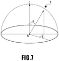
- FIG. 7 is a schematic diagram explaining an elevation angle ⁇ and an azimuth angle ⁇ for an object at the time of image capturing;
- FIG. 8 is a flowchart showing a color difference information derivation processing procedure example
- FIG. 9 is a diagram showing a UI provided by a display control unit
- FIG. 10 is a diagram showing a UI provided by the display control unit
- FIG. 11 is a diagram showing a UI provided by the display control unit
- FIG. 12 is an explanatory diagram of angle information derivation processing
- FIG. 13 is a diagram showing a UI provided by the display control unit
- FIG. 14 is a function block diagram showing a software configuration of the image processing apparatus
- FIG. 15 is a flowchart showing a color difference information display processing procedure example
- FIG. 16 is a diagram showing an example of reference color difference data
- FIG. 17 is a diagram showing a UI provided by the display control unit.
- FIG. 1 is a block diagram showing an example of a hardware configuration of an image processing apparatus of the present embodiment.
- an image processing apparatus 100 of the present embodiment includes a CPU 101 , a RAM 102 , an HDD 103 , a general-purpose interface (hereinafter, interface is described as “I/F”) 104 , and a monitor 108 .
- Those units are connected to one another so as to be capable of transmission and reception of data by a main bus 109 .
- the general-purpose I/F 104 connects an image capturing apparatus 105 , such as a camera, an input device 106 , such as a mouse and a keyboard, and an external memory 107 , such as a memory card, a CF card, an SD card, and a USB memory, to the main bus 109 .
- an image capturing apparatus 105 such as a camera
- an input device 106 such as a mouse and a keyboard
- an external memory 107 such as a memory card, a CF card, an SD card, and a USB memory
- the CPU 101 boots an image processing application stored in the HDD 103 and displays a user interface (UI) on the monitor 108 as well as loading the image processing application onto the RAM 102 .
- UI user interface
- various kinds of data stored in the HDD 103 and the external memory 107 object information on an object relating to the shape, the position at the time of image capturing and the like, image data captured by the image capturing apparatus 105 , instructions from the input device 106 and the like are transferred to the RAM 102 .
- the image capturing apparatus 105 is provided with a sensor for acquiring external parameters of the image capturing apparatus 105 , that is, image capturing orientation information on the image capturing position, the image capturing orientation and the like of the image capturing apparatus 105 .
- a GPS sensor position sensor
- a geomagnetic sensor azimuth sensor
- various arithmetic operations are performed for the image data stored in the RAM 102 based on instructions from the CPU 101 . Arithmetic operation results are displayed on the monitor 108 , stored in the HDD 103 or the external memory 107 and the like.
- FIG. 2 is a function block diagram showing a software configuration of the image processing apparatus 100 .
- the image processing apparatus 100 of the present embodiment has an image capturing orientation information acquisition unit (first acquisition unit) 201 , a shape/position data acquisition unit (second acquisition unit) 202 , an angle derivation unit (light receiving angle derivation unit) 203 , an image acquisition unit 204 , a color difference derivation unit 205 , and a display control unit 206 .
- the function of each unit shown in FIG. 2 is implemented by the CPU 11 reading a program stored within the HDD 103 and executing the program. It may also be possible to configure an image processing apparatus including a dedicated processing circuit corresponding to each unit.
- the image capturing orientation information acquisition unit 201 acquires image capturing orientation information on the image capturing apparatus 105 based on instructions from the CPU 101 .
- the image capturing orientation information includes image capturing position information indicating the image capturing position of the image capturing apparatus 105 and image capturing orientation information indicating the image capturing direction at the time of image capturing of the image capturing apparatus 105 .
- the shape/position data acquisition unit 202 acquires object information relating to the shape of an object, which is an image capturing target, the position thereof and the like.
- the data acquired as the object information is called shape/position data.
- the shape/position data includes, for example, vertex coordinates (x, y, z) of a polygon (normally, triangle) and has polygon data described by a set of surfaces determined based on combinations of the vertexes.
- the polygon data is associated with normal information derived by a publicly known technique and the shape/position data is stored in advance in the HDD 103 , the external memory 107 and the like.
- the angle derivation unit 203 derives a light receiving angle at each point of an object based on the image capturing orientation information acquired by the image capturing orientation information acquisition unit 201 and the shape/position data acquired by the shape/position data acquisition unit 202 based on the instructions from the CPU 101 .
- the light receiving angle is an angle formed by the direction in which the sensor surface of the image capturing apparatus receives the light reflecting from the object and the normal of the object at the point from which the light reflects and details will be described later. That is, the angle derivation unit 203 derives the light receiving angle at each polygon surface of the polygon data based on the image capturing orientation information on the image capturing apparatus 105 and the shape data of the object.
- the derived light receiving angle is stored in the RAM 102 , the HDD 103 and the like.
- the image acquisition unit 204 acquires image data representing an image obtained by the image capturing apparatus 105 capturing the object based on the instructions from the CPU 101 .
- the image data is data having two-dimensional color information.
- the color information may be in any format, for example, such as RGB, XYZ, and Lab value. In the present embodiment, it is assumed that the color information is device-independent tri-stimulus values XYZ.
- the image acquisition unit 204 performs color conversion for the two-dimensional color information of the image data based on the instructions from the CPU 101 . That is, the image acquisition unit 204 has a function to acquire image data, a function to acquire color information from image data, and a function to convert color information.
- the color difference derivation unit 205 derives color difference information on the object based on the two-dimensional color information included in the image data acquired by the image acquisition unit 204 and the angle (light receiving angle) derived by the angle derivation unit 203 based on the instructions from the CPU 101 .
- the display control unit 206 displays the color difference information derived by the color difference derivation unit 205 on the monitor 108 based on the instructions from the CPU 101 . Details of the display processing by the display control unit 206 will be described later.
- FIG. 3 is a flowchart showing a procedure example of the color difference derivation result display processing by the image processing apparatus 100 .
- Each symbol S in the following means that the step is a step in the flowchart.
- the image acquisition unit 204 acquires image data obtained by capturing an object.
- the image data is image data having device-independent tri-stimulus values XYZ obtained by capturing each pixel by the image capturing apparatus 105 .
- the image acquisition unit 204 converts the XYZ values of the image data acquired at S 301 into L*a*b* by using the color conversion formula specified by the CIE.
- the shape/position data acquisition unit 202 acquires the shape/position data of the object stored in the HDD 103 or the external memory 107 .
- the shape/position data is data including polygon data having a plurality of polygon surfaces with which the normal information on each surface is associated and position information on the object at the time of image capturing by the image capturing apparatus 105 .
- the image capturing orientation information acquisition unit 201 acquires the image capturing orientation information including information indicating the image capturing position of the image capturing apparatus 105 at the time of capturing the object (object) and information indicating the image capturing orientation thereof.
- the image capturing orientation information acquisition unit 201 acquires information indicating the image capturing position of the camera and information indicating the direction (image capturing orientation) thereof, detected by the GPS sensor and the geomagnetic sensor, respectively, mounted on the image capturing apparatus 105 .
- the angle derivation unit 203 derives the light receiving angle (angle) for each position of the object. Details of the derivation method of a light receiving angle will be described later.
- the color difference derivation unit 205 derives color difference information in accordance with the light receiving angle based on the color information obtained at S 302 and the information on the light receiving angle derived at S 305 . Details of the derivation method of color difference information in accordance with a light receiving angle will be described later.
- the display control unit 206 displays the results of the color difference information derived at S 306 on the monitor 108 .
- FIG. 5 is the schematic diagram for explaining angle information derivation processing and is the schematic diagram representing the position relationship between the object and the image capturing apparatus two-dimensionally.
- symbol A indicates the viewpoint position of the image capturing apparatus 105
- symbol Bi indicates the center position of a certain polygon surface in an object 501 .
- symbol 502 indicates a virtual screen in the world coordinate system set in accordance with the focus length and the resolution of the image capturing apparatus 105 . It is possible to call the screen 502 by another term a projection surface of an object for the image capturing element of the image capturing apparatus 105 .
- Symbol Pi on the screen 502 indicates the pixel of an image capturing element.
- the subscript i of symbol Pi is an integer N larger than or equal to 1 and indicates the pixel position.
- the number N of pixels is set in accordance with the resolution of the image capturing apparatus 105 .
- the subscript i of symbol Bi is set in accordance with the pixel Pi on the screen 502 , at which a segment connecting the viewpoint position A of the image capturing apparatus 105 and the center position of a certain polygon surface intersects with the screen 502 .
- the object is illuminated uniformly from a position a sufficient distance apart from the object.
- the position is not limited to the center position of a polygon surface. Note that, it is desirable to use a position in common to each polygon surface.
- FIG. 4 is a flowchart showing an angle information derivation processing procedure example.
- the angle derivation unit 203 sets the screen 502 for the viewpoint position A based on the image capturing orientation information (information on the position and orientation of the image capturing apparatus 105 ) acquired at S 304 . That is, the angle derivation unit 203 sets the viewpoint position A of the image capturing apparatus 105 , shape data corresponding to the object 501 , and the screen 502 in a virtual global coordinate system space.
- the angle derivation unit 203 sets the pixel Pi on the screen 502 . It is assumed that the subscript i of the pixel Pi is an integer from 1 to N and set in accordance with the resolution or the like of the image capturing apparatus.
- the angle derivation unit 203 determines whether or not a polygon surface (polygon mesh) corresponding to the object 501 exists in a vector direction from the viewpoint position A of the image capturing apparatus 105 toward the pixel Pi.
- equation 1 which is a general equation of intersection determination of a ray (line of sight) and a polygon surface, used generally in the CG field is used.
- A is the viewpoint position of the image capturing apparatus 105
- Pi is the position of the pixel of the screen 502
- Bi is the center position of the polygon surface, corresponding to the pixel Pi
- O is a position in the direction of the normal for the center position Bi of the polygon surface.
- APi is a vector indicating the line of sight of the image capturing apparatus 105
- BiO is a normal vector of the center position on the polygon surface.
- t is a parameter indicating a relationship between the ray and the polygon surface.
- FIG. 6 is a diagram for explaining the center position of a certain polygon surface and the normal direction.
- Symbols B 1 , B 2 , and B 3 indicate each vertex in a case where a certain polygon surface (polygon mesh) is triangular.
- Symbol Bi indicates the center position in the polygon surface having the three vertexes B 1 , B 2 , and B 3 .
- Symbol O indicates the normal direction for the center position Bi in the polygon surface.
- the angle derivation unit 203 derives t by using equation 1.
- the angle derivation unit 203 determines that a polygon surface corresponding to a certain local area of the object 501 exists in the direction of the vector APi. In a case where the angle derivation unit 203 determines that a polygon surface exists, the processing advances to S 405 .
- the angle derivation unit 203 determines that a polygon surface corresponding to a certain local area of the object 501 does not exist in the direction of the vector APi. In a case where the angle derivation unit 203 determines that a polygon surface does not exist, the processing advances to S 404 .
- the angle derivation unit 203 determines that a polygon surface does not exist at S 403 regarding the pixel Pi set at S 402 , and therefore, no object exists in the direction of the vector APi and NULL is stored in the memory (RAM 102 ). After NULL is stored in the memory, the processing advances to S 406 .
- the angle derivation unit 203 derives the angle (light receiving angle) formed by the vector APi and the vector BiO regarding the pixel Pi set at S 402 and stores the derived angle in the memory (RAM 102 ).
- AP (a1, a2, a3)
- BO (b1, b2, b3)
- This angle ⁇ represents the image capturing angle for the polygon surface of a certain local area on the surface of the object.
- an angle ⁇ in the azimuth angle direction is also an angle that affects the light reflection distribution. Consequently, by deriving the azimuth angle ⁇ in addition to the angle ⁇ in the elevation angle direction, regarding the color difference for the angle, it is possible to drive in more detail the average color difference for each angle and the color difference variation width within the angle range.
- the angle ⁇ in the azimuth angle direction is represented by equation 3 below.
- the derivation of the angle in the azimuth angle direction is not performed and it is assumed that an average color difference ⁇ E max min, ⁇ for each angle and a color difference variation width ⁇ E all, ⁇ within the angle range (within the image capturing angle) are derived, respectively, regarding the color difference for the angle in the elevation angle direction.
- the angle derivation unit 203 sets all the pixels as the pixel Pi and determines whether or not the angle derivation processing is performed. In a case where there is an unprocessed pixel, the processing returns to S 402 and the angle derivation unit 203 sets another pixel other than the pixel for which the angle derivation processing has been performed as the pixel Pi. Then, the angle derivation unit 203 performs the determination of whether or not a polygon surface exists in the direction of the vector APi and stores the determination results in the memory as previously at S 403 to S 405 for the pixel Pi set anew at S 402 . Then, in a case where the angle derivation unit 203 determines that the angle determination processing is performed for all the pixels, this processing is terminated.
- FIG. 8 is a flowchart showing a color difference information derivation processing procedure example.
- an angle range is set, for which an angle calculation is performed in accordance with instructions of a user for the input device 106 .
- an angle range is set from ⁇ 45 degree to +45 degrees at five-degree intervals
- a total of 18 angle ranges are set.
- the angle interval is not limited to five degrees and it is possible to arbitrarily set in accordance with instructions of a user. Further, it is assumed that the lower limit value of each angle range is larger than or equal to the angle and the upper limit value is less than the angle.
- the color difference derivation unit 205 sets the angle of each pixel derived at S 305 to the corresponding angle range.
- which of a plurality of angle ranges the angle derived at S 305 corresponds to is determined and the corresponding angle range is set in accordance with results of the determination. For example, in a case where the angle derived at S 305 is 23 degrees, the color difference derivation unit 205 determines that 23 degrees corresponds to the angle range not less than 20 degrees and less than 25 degrees and sets 23 degrees to the angle range not less than 20 degrees and less than 25 degrees.
- the color difference derivation unit 205 derives average values L* ave, ⁇ , a* ave, ⁇ , and b* ave, ⁇ of L*a*b* for each angle range set at S 802 .
- each average value each of equation 4, equation 5, and equation 6 below is used.
- N in equation 4 is a quantity of L* within the angle range
- N in equation 5 is a quantity of a* within the angle range
- N in equation 6 is a quantity of b* within the angle range.
- the subscripts “i” and “j” of L*, a*, and b* indicate a pixel on the screen and “i” indicates the pixel position in the horizontal direction of the screen 502 in FIG. 5 and “j” indicates the pixel position in the direction perpendicular to that of “i” of the screen 502 in FIG. 5 .
- the color difference derivation unit 205 derives a color difference ⁇ E i, j, ⁇ from L i, j, ⁇ , a i, j, ⁇ , and b i, j, ⁇ of all the pixels and a color difference ⁇ E ave, ⁇ from L* ave, ⁇ a* ave, ⁇ b* ave, ⁇ derived at S 803 for a Lab value L* 0 a* 0 b* 0 , which is an arbitrary reference.
- L* 0 a* 0 b* 0 is a numerical value that is set in accordance with color information on an object.
- Equation 7 For the derivation of the color difference ⁇ E i, j, ⁇ , equation 7 below is used and for the derivation of the color difference ⁇ E ave, ⁇ , equation 8 below is used.
- Equation 7 the subscripts “i” and “j” of ⁇ E, L*, a*, and b* indicate the pixel on the screen, respectively, as in equation 4 to equation 6 described above.
- the color difference derivation unit 205 derives a within-identical angle color difference (hereinafter, also referred to as average color difference for each angle), which is a variation amount in the color difference between the maximum value and the minimum value for each ⁇ in a predetermined angle range for the color difference ⁇ E i, j, ⁇ derived by equation 7 at S 804 .
- average color difference for each angle a within-identical angle color difference
- equation 9 For the derivation of the average color difference for each angle, equation 9 below is used. [Equation 9]
- ⁇ E max min, ⁇ max( ⁇ E i,j, ⁇ ) ⁇ min( ⁇ E i,j, ⁇ ) (9)
- the color difference derivation unit 205 derives a color difference due to a change in angle (hereinafter, also referred to as color difference variation width within the angle range), which is the variation amount of the color difference due to a change in the angle range for the color difference ⁇ E ave, ⁇ derived by equation 8 at S 804 .
- ⁇ E max min, ⁇ which is the derivation results by equation 9, takes only the color difference within a predetermined angle range not affected by a change in color due to angle as an arithmetic operation target and is a numerical value derived by regarding the angle within a predetermined angle range being the identical angle. Because of this, it is made possible for a user to identify the derived ⁇ E max min, ⁇ as information on color unevenness that is not affected by a change in angle of the paint, that is, not affected by a change in color due to angle.
- ⁇ E all, ⁇ which is the derivation results by equation 10, is a numerical value derived by taking the color difference within the angle range as an arithmetic operation target.
- the color difference is derived for the elevation angle ⁇ and in a case where the azimuth angle ⁇ is also measured, it is also possible to derive a color difference by combining the elevation angle ⁇ and the azimuth angle ⁇ .
- FIG. 9 to FIG. 11 are each a diagram showing an example of the UI provided by the display control unit.
- the color difference map represents the degree (magnitude) of the color difference and in the color difference map, the color difference of white is the smallest and the color difference of black is the largest, and the gradation from white to black represents a gradual increase in the magnitude of the color difference.
- FIG. 9 shows a case where six ranges are set.
- a color difference map 902 As shown in FIG. 9 , on a UI screen 901 , a color difference map 902 , an average color difference 903 , and a color difference variation width 904 are displayed in correspondence to each of angle ranges ⁇ 1 to ⁇ 2 , ⁇ 2 to ⁇ 3 , ⁇ 3 to ⁇ 4 , ⁇ 4 to ⁇ 5 , ⁇ 5 to ⁇ 6 , and ⁇ 6 to ⁇ 7 .
- the average color difference 903 for example, the average color difference ⁇ E max, min, ⁇ for each angle, which is the derivation results by equation 9, is displayed.
- the color difference variation width 904 for example, the color difference variation width ⁇ E all, ⁇ within the angle range, which is the derivation results by equation 10, is displayed.
- the average color difference for each angle and the color difference variation width within the angle range as described above, it is made possible to identify the color unevenness based on the average color difference for each angle and to identify a change in color due to angle based on the color difference variation width within the angle range.
- FIG. 10 it is also possible to display a graph 1005 of color difference derivation results and a color difference variation width 1006 due to change in angle, in addition to a color difference map 1002 , an average color difference 1003 , and a color difference variation width 1004 , in accordance with a specific angle range on a UI screen 1001 .
- the color difference map 1002 , the average color difference 1003 , and the color difference variation width 1004 show a case of the angle range ⁇ 1 to ⁇ 2 .
- the graph 1005 is a graph created by turning the representative angle and the average color difference in each angle range into a graph in association with each other. Further, at each representative angle, the color difference variation width 1006 is shown. In a case where there is a representative angle whose color difference variation width is large compared to another representative angle, it is possible for a user to determine that the possibility is strong that the color unevenness of the coating occurs in the angle range.
- FIG. 12 is a schematic diagram for explaining the angle information derivation processing, a schematic diagram showing the position relationship between the object and the image capturing apparatus two-dimensionally.
- symbol B indicates the center position of one of the planes of a flat plate having one inflection point, that is, an object 1201 configured by two planes.
- the image capturing apparatus 105 and the object 1201 are in the state where the distance therebetween is sufficiently long.
- an image capturing angle corresponding to each of two surfaces is obtained as the angle ⁇ .
- An example of the UI provided by the display control unit 206 in this case is shown in FIG. 13 .
- FIG. 13 it is also possible to display color difference maps 1302 and 1305 , average color differences 1303 and 1306 , and color difference variation widths 1304 and 1307 corresponding to each of two kinds of angle range (angle) on a UI screen 1301 . Further, it is also possible to display a graph 1308 of color difference data for each angle, which is color difference derivation results, on the UI screen 1301 . Even in a case of the object in which the angle changes locally as described above, by applying the present embodiment, it is made possible to analyze the color difference for a surface whose angle is constant.
- the image capturing angle for the image capturing apparatus in a local area on the surface in an object corresponding to each pixel is derived for each of the pixels in the image data. Then, based on the color difference between the color information on each pixel and the reference value, the average color difference for each predetermined image capturing angle and the color difference variation width within the image capturing angle are derived and the average color difference for each predetermined image capturing angle and the color difference variation width within the image capturing angle are displayed on the monitor 108 . Due to this, it is made possible to provide information for a user to identify color unevenness based on the average color difference for each predetermined image capturing angle and to identify a change in color due to angle based on the color difference variation width within the image capturing angle.
- the average color difference which is a color difference within the identical angle range
- the color difference variation width which is a color difference due to a change in angle
- an image processing apparatus which has a color difference determination unit configured to determine a color difference within a predetermined angle range and a color difference due to a change in angle based on a reference color difference, and which displays determination results on a display control unit.
- FIG. 14 is a block diagram showing a function configuration example of the image processing apparatus.
- the same symbol is attached to the same function unit as that of the first embodiment and explanation thereof is omitted.
- the image processing apparatus 100 of the present embodiment further has a reference color difference acquisition unit (determination value acquisition unit) 1401 and a color difference determination unit 1402 .
- the reference color difference acquisition unit 1401 acquires a reference color difference, which is a determination value.
- the color difference determination unit 1402 compares the color difference derived by the color difference derivation unit 205 with the reference color difference acquired by the reference color difference acquisition unit 1401 and transmits comparison results to the display control unit 206 .
- FIG. 15 is a flowchart showing a processing example of color difference derivation result display processing by the image processing apparatus of the second embodiment.
- Each symbol S in the following means that the step is a step in the flowchart.
- the same symbol is attached to the same step as that in FIG. 3 and explanation thereof is omitted appropriately.
- the reference color difference acquisition unit 1401 acquires reference color difference data, which is a reference value for determining a color difference, stored in the external memory 107 in response to user instructions being input to the input device 106 .
- Examples of reference color differences in the present embodiment are shown in FIG. 16 .
- FIG. 16 is a table showing an example of reference color difference data.
- the reference color difference corresponding to a within-predetermined angle (within-identical angle) and the reference color difference corresponding to a change in angle are set for each member (material) and paint as shown in FIG. 16 .
- the reference color difference (determination reference) within the table is acquired by holding in advance the table in FIG.
- the reference color difference table is not limited to the reference color difference table showing a relationship between members (materials) and paints (coatings) and it is possible to design a reference color difference table showing a relationship with characteristics of an object, which may affect a within-identical angle color difference and a color difference due to a change in angle.
- the factor of occurrence of a color difference is explained.
- the color difference within a predetermined angle is affected significantly by the coating unevenness and in a case where there is coating unevenness, the color difference becomes large in accordance with the magnitude of the coating unevenness.
- the color difference due to a change in angle is the characteristics possessed originally by the paint and in a case where the object is a production part, the shape changes due to a manufacturing error and the angle of the object at the time of measurement changes, and therefore, a color difference occurs.
- the color difference determination unit 1402 compares the color difference (acquired color difference) derived by the color difference derivation unit 205 at S 306 with the reference color difference (determination reference) acquired at S 1501 . Acquired comparison results are sent to the display control unit 206 .
- FIG. 17 is a diagram showing an example of a UI provided by the display control unit. As shown in FIG. 17 , on a UI screen 1701 , as in FIG.
- a color map 1702 an average color difference 1703 , a color difference variation width 1704 , a graph 1705 of color difference derivation results, and a color difference variation width due to change in angle 1706 in accordance with a specific angle range are displayed.
- a member 1711 of an object, a paint 1712 of an object, a within-identical angle regarding reference color difference 1713 , and a color difference due to change in angle regarding reference color difference 1714 are displayed.
- a within-identical angle regarding measurement results 1715 a color difference due to change in angle regarding measurement results 1716 , and respective determination results 1717 and 1718 are displayed.
- the color of the numerical value display in place of the display of OK and NG
- the within-identical angle color difference average color difference for each predetermined angle
- the color difference due to a change in angle color difference variation width within an image capturing angle
- the comparison results (determination results) by the color difference determination unit 1402 of the present embodiment are displayed on the monitor 108 , and thereby, it is made possible for a user to check the comparison results. As a result of this, it is made possible for a user to determine as follows.
- the cause of a color difference is color unevenness, such as that the influence of the coating unevenness is exerted in a case where the determination results within the identical angle are NG
- the cause of a color difference is a change in color due to angle, such as that the influence of the color shift due to the error of the shape is exerted in a case where the determination of the color difference due to a change in angle is NG.
- the reference color difference set in advance in accordance with the member and the paint of an object is compared with the measurement results of the within-identical angle color difference and the color difference due to a change in angle, respectively, and the comparison results are displayed on the monitor 108 . Because of this, it is made possible for a user to easily identify whether the cause of a color difference is color unevenness or a change in color due to angle.
- the image capturing orientation information is acquired after acquiring the shape/position data
- a method may be accepted in which the image data captured by the image capturing apparatus is processed on the image processing hardware within the image capturing apparatus.
- Embodiment(s) of the present invention can also be realized by a computer of a system or apparatus that reads out and executes computer executable instructions (e.g., one or more programs) recorded on a storage medium (which may also be referred to more fully as a ‘non-transitory computer-readable storage medium’) to perform the functions of one or more of the above-described embodiment(s) and/or that includes one or more circuits (e.g., application specific integrated circuit (ASIC)) for performing the functions of one or more of the above-described embodiment(s), and by a method performed by the computer of the system or apparatus by, for example, reading out and executing the computer executable instructions from the storage medium to perform the functions of one or more of the above-described embodiment(s) and/or controlling the one or more circuits to perform the functions of one or more of the above-described embodiment(s).
- computer executable instructions e.g., one or more programs
- a storage medium which may also be referred to more fully as a
- the computer may comprise one or more processors (e.g., central processing unit (CPU), micro processing unit (MPU)) and may include a network of separate computers or separate processors to read out and execute the computer executable instructions.
- the computer executable instructions may be provided to the computer, for example, from a network or the storage medium.
- the storage medium may include, for example, one or more of a hard disk, a random-access memory (RAM), a read only memory (ROM), a storage of distributed computing systems, an optical disk (such as a compact disc (CD), digital versatile disc (DVD), or Blu-ray Disc (BD)TM), a flash memory device, a memory card, and the like.
Landscapes
- Engineering & Computer Science (AREA)
- Multimedia (AREA)
- Theoretical Computer Science (AREA)
- Physics & Mathematics (AREA)
- General Physics & Mathematics (AREA)
- Signal Processing (AREA)
- Computing Systems (AREA)
- Image Analysis (AREA)
- Image Processing (AREA)
- Spectrometry And Color Measurement (AREA)
- Color Image Communication Systems (AREA)
Abstract
Description
[Equation 7]
ΔE i,j,θ=√{square root over ((L* i,j,θ −L* 0)2+(a* i,j,θ −a* 0)2+(b* i,j,θ −b* 0)2)} (7)
[Equation 8]
ΔE ave,θ=√{square root over ((L* ave,θ −L* 0)2+(a* ave,θ −a* 0)2+(b* ave,θ −b* 0)2)} (8)
[Equation 9]
ΔE max min,θ=max(ΔE i,j,θ)−min(ΔE i,j,θ) (9)
[Equation 10]
ΔE all,θ=max(ΔE ave,θ)−min(ΔE ave,θ) (10)
Claims (20)
Applications Claiming Priority (2)
| Application Number | Priority Date | Filing Date | Title |
|---|---|---|---|
| JP2018-091570 | 2018-05-10 | ||
| JP2018091570A JP2019197002A (en) | 2018-05-10 | 2018-05-10 | Image processing device, image processing method, and program |
Publications (2)
| Publication Number | Publication Date |
|---|---|
| US20190349521A1 US20190349521A1 (en) | 2019-11-14 |
| US10728448B2 true US10728448B2 (en) | 2020-07-28 |
Family
ID=68463413
Family Applications (1)
| Application Number | Title | Priority Date | Filing Date |
|---|---|---|---|
| US16/396,136 Expired - Fee Related US10728448B2 (en) | 2018-05-10 | 2019-04-26 | Image processing apparatus, image processing method and storage medium to obtain a color difference of an object |
Country Status (2)
| Country | Link |
|---|---|
| US (1) | US10728448B2 (en) |
| JP (1) | JP2019197002A (en) |
Families Citing this family (1)
| Publication number | Priority date | Publication date | Assignee | Title |
|---|---|---|---|---|
| US11285368B2 (en) * | 2018-03-13 | 2022-03-29 | Vc Inc. | Address direction guiding apparatus and method |
Citations (5)
| Publication number | Priority date | Publication date | Assignee | Title |
|---|---|---|---|---|
| JP2000205846A (en) | 1999-01-13 | 2000-07-28 | Nissan Motor Co Ltd | Painting unevenness inspection apparatus and method |
| US9906740B2 (en) | 2015-10-05 | 2018-02-27 | Canon Kabushiki Kaisha | Image processing apparatus, image processing method, and medium for noise reduction |
| US10198872B2 (en) * | 2015-08-10 | 2019-02-05 | The Board Of Trustees Of The Leland Stanford Junior University | 3D reconstruction and registration of endoscopic data |
| US20190279388A1 (en) * | 2018-03-06 | 2019-09-12 | Omron Corporation | Image inspecting apparatus, image inspecting method and image inspecting program |
| US10417751B2 (en) * | 2016-10-24 | 2019-09-17 | Hitachi, Ltd. | Image processing apparatus, warning apparatus, image processing system, and image processing method |
-
2018
- 2018-05-10 JP JP2018091570A patent/JP2019197002A/en active Pending
-
2019
- 2019-04-26 US US16/396,136 patent/US10728448B2/en not_active Expired - Fee Related
Patent Citations (5)
| Publication number | Priority date | Publication date | Assignee | Title |
|---|---|---|---|---|
| JP2000205846A (en) | 1999-01-13 | 2000-07-28 | Nissan Motor Co Ltd | Painting unevenness inspection apparatus and method |
| US10198872B2 (en) * | 2015-08-10 | 2019-02-05 | The Board Of Trustees Of The Leland Stanford Junior University | 3D reconstruction and registration of endoscopic data |
| US9906740B2 (en) | 2015-10-05 | 2018-02-27 | Canon Kabushiki Kaisha | Image processing apparatus, image processing method, and medium for noise reduction |
| US10417751B2 (en) * | 2016-10-24 | 2019-09-17 | Hitachi, Ltd. | Image processing apparatus, warning apparatus, image processing system, and image processing method |
| US20190279388A1 (en) * | 2018-03-06 | 2019-09-12 | Omron Corporation | Image inspecting apparatus, image inspecting method and image inspecting program |
Also Published As
| Publication number | Publication date |
|---|---|
| US20190349521A1 (en) | 2019-11-14 |
| JP2019197002A (en) | 2019-11-14 |
Similar Documents
| Publication | Publication Date | Title |
|---|---|---|
| EP1754191B1 (en) | Characterizing a digital imaging system | |
| US10497111B2 (en) | Information processing apparatus and method of selecting viewpoint for measuring object, and measuring system | |
| EP3668077B1 (en) | Image processing system, server device, image processing method, and image processing program | |
| US20170205291A1 (en) | Measurement system, information processing apparatus, information processing method, and medium | |
| US9064178B2 (en) | Edge detection apparatus, program and method for edge detection | |
| US10837903B2 (en) | Information processing apparatus, method of deriving reflection characteristics, program, and reflection characteristic profile | |
| US20150339833A1 (en) | Control apparatus, robot, and control method | |
| US11100699B2 (en) | Measurement method, measurement device, and recording medium | |
| CN110268223A (en) | Three-dimensional shape measuring device, three-dimensional shape measuring method, and program | |
| US10726569B2 (en) | Information processing apparatus, information processing method, and non-transitory computer-readable storage medium | |
| US20160284102A1 (en) | Distance measurement apparatus, distance measurement method, and storage medium | |
| US8594416B2 (en) | Image processing apparatus, image processing method, and computer program | |
| US20190128806A1 (en) | Reflection characteristic measurement apparatus, machining system, reflection characteristic measurement method, object machining method, and non-transitory computer-readable storage medium | |
| US20170142384A1 (en) | Image processing apparatus, image processing method, image projection system, and storage medium | |
| US20150002662A1 (en) | Information processing apparatus, measurement system, control system, light amount determination method and storage medium | |
| JP7154786B2 (en) | Image processing device, image processing method and program | |
| US10728448B2 (en) | Image processing apparatus, image processing method and storage medium to obtain a color difference of an object | |
| US10097736B2 (en) | Image processing device and image processing method | |
| US9317938B2 (en) | Image processing apparatus and control method therefor | |
| JP7503443B2 (en) | Display MTF measuring device and program thereof | |
| US20140152862A1 (en) | Image processing apparatus, image pickup apparatus, image pickup system, image processing method, and non-transitory computer-readable storage medium | |
| JP2011243138A (en) | Image processing apparatus, image processing method and computer program | |
| JP2016072691A (en) | Image processing apparatus, control method therefor, and program | |
| JP2015141440A (en) | Image processing method and image processor | |
| JP5376077B1 (en) | Measuring position determining device, measuring position determining method, image display system, program |
Legal Events
| Date | Code | Title | Description |
|---|---|---|---|
| FEPP | Fee payment procedure |
Free format text: ENTITY STATUS SET TO UNDISCOUNTED (ORIGINAL EVENT CODE: BIG.); ENTITY STATUS OF PATENT OWNER: LARGE ENTITY |
|
| AS | Assignment |
Owner name: CANON KABUSHIKI KAISHA, JAPAN Free format text: ASSIGNMENT OF ASSIGNORS INTEREST;ASSIGNOR:MANABE, YOSHIHIRO;REEL/FRAME:050658/0900 Effective date: 20190910 |
|
| STPP | Information on status: patent application and granting procedure in general |
Free format text: NOTICE OF ALLOWANCE MAILED -- APPLICATION RECEIVED IN OFFICE OF PUBLICATIONS |
|
| STPP | Information on status: patent application and granting procedure in general |
Free format text: PUBLICATIONS -- ISSUE FEE PAYMENT VERIFIED |
|
| STCF | Information on status: patent grant |
Free format text: PATENTED CASE |
|
| FEPP | Fee payment procedure |
Free format text: MAINTENANCE FEE REMINDER MAILED (ORIGINAL EVENT CODE: REM.); ENTITY STATUS OF PATENT OWNER: LARGE ENTITY |
|
| LAPS | Lapse for failure to pay maintenance fees |
Free format text: PATENT EXPIRED FOR FAILURE TO PAY MAINTENANCE FEES (ORIGINAL EVENT CODE: EXP.); ENTITY STATUS OF PATENT OWNER: LARGE ENTITY |
|
| STCH | Information on status: patent discontinuation |
Free format text: PATENT EXPIRED DUE TO NONPAYMENT OF MAINTENANCE FEES UNDER 37 CFR 1.362 |
|
| FP | Lapsed due to failure to pay maintenance fee |
Effective date: 20240728 |