US10727372B2 - Dilute-Antimonide group-III-Nitride nanostructure optoelectronic devices - Google Patents
Dilute-Antimonide group-III-Nitride nanostructure optoelectronic devices Download PDFInfo
- Publication number
- US10727372B2 US10727372B2 US16/030,855 US201816030855A US10727372B2 US 10727372 B2 US10727372 B2 US 10727372B2 US 201816030855 A US201816030855 A US 201816030855A US 10727372 B2 US10727372 B2 US 10727372B2
- Authority
- US
- United States
- Prior art keywords
- quantum
- layer
- gan
- disposed
- nanowires
- Prior art date
- Legal status (The legal status is an assumption and is not a legal conclusion. Google has not performed a legal analysis and makes no representation as to the accuracy of the status listed.)
- Active
Links
Images


Classifications
-
- H01L33/325—
-
- H—ELECTRICITY
- H10—SEMICONDUCTOR DEVICES; ELECTRIC SOLID-STATE DEVICES NOT OTHERWISE PROVIDED FOR
- H10H—INORGANIC LIGHT-EMITTING SEMICONDUCTOR DEVICES HAVING POTENTIAL BARRIERS
- H10H20/00—Individual inorganic light-emitting semiconductor devices having potential barriers, e.g. light-emitting diodes [LED]
- H10H20/80—Constructional details
- H10H20/81—Bodies
- H10H20/822—Materials of the light-emitting regions
- H10H20/824—Materials of the light-emitting regions comprising only Group III-V materials, e.g. GaP
- H10H20/825—Materials of the light-emitting regions comprising only Group III-V materials, e.g. GaP containing nitrogen, e.g. GaN
- H10H20/8252—Materials of the light-emitting regions comprising only Group III-V materials, e.g. GaP containing nitrogen, e.g. GaN characterised by the dopants
-
- H01L27/156—
-
- H01L33/0075—
-
- H01L33/06—
-
- H01L33/08—
-
- H01L33/18—
-
- H01L33/20—
-
- H01L33/24—
-
- H01L33/32—
-
- H01L33/42—
-
- H01L33/44—
-
- H—ELECTRICITY
- H10—SEMICONDUCTOR DEVICES; ELECTRIC SOLID-STATE DEVICES NOT OTHERWISE PROVIDED FOR
- H10H—INORGANIC LIGHT-EMITTING SEMICONDUCTOR DEVICES HAVING POTENTIAL BARRIERS
- H10H20/00—Individual inorganic light-emitting semiconductor devices having potential barriers, e.g. light-emitting diodes [LED]
- H10H20/01—Manufacture or treatment
- H10H20/011—Manufacture or treatment of bodies, e.g. forming semiconductor layers
- H10H20/013—Manufacture or treatment of bodies, e.g. forming semiconductor layers having light-emitting regions comprising only Group III-V materials
- H10H20/0137—Manufacture or treatment of bodies, e.g. forming semiconductor layers having light-emitting regions comprising only Group III-V materials the light-emitting regions comprising nitride materials
-
- H—ELECTRICITY
- H10—SEMICONDUCTOR DEVICES; ELECTRIC SOLID-STATE DEVICES NOT OTHERWISE PROVIDED FOR
- H10H—INORGANIC LIGHT-EMITTING SEMICONDUCTOR DEVICES HAVING POTENTIAL BARRIERS
- H10H20/00—Individual inorganic light-emitting semiconductor devices having potential barriers, e.g. light-emitting diodes [LED]
- H10H20/80—Constructional details
- H10H20/81—Bodies
- H10H20/811—Bodies having quantum effect structures or superlattices, e.g. tunnel junctions
- H10H20/812—Bodies having quantum effect structures or superlattices, e.g. tunnel junctions within the light-emitting regions, e.g. having quantum confinement structures
-
- H—ELECTRICITY
- H10—SEMICONDUCTOR DEVICES; ELECTRIC SOLID-STATE DEVICES NOT OTHERWISE PROVIDED FOR
- H10H—INORGANIC LIGHT-EMITTING SEMICONDUCTOR DEVICES HAVING POTENTIAL BARRIERS
- H10H20/00—Individual inorganic light-emitting semiconductor devices having potential barriers, e.g. light-emitting diodes [LED]
- H10H20/80—Constructional details
- H10H20/81—Bodies
- H10H20/813—Bodies having a plurality of light-emitting regions, e.g. multi-junction LEDs or light-emitting devices having photoluminescent regions within the bodies
-
- H—ELECTRICITY
- H10—SEMICONDUCTOR DEVICES; ELECTRIC SOLID-STATE DEVICES NOT OTHERWISE PROVIDED FOR
- H10H—INORGANIC LIGHT-EMITTING SEMICONDUCTOR DEVICES HAVING POTENTIAL BARRIERS
- H10H20/00—Individual inorganic light-emitting semiconductor devices having potential barriers, e.g. light-emitting diodes [LED]
- H10H20/80—Constructional details
- H10H20/81—Bodies
- H10H20/817—Bodies characterised by the crystal structures or orientations, e.g. polycrystalline, amorphous or porous
- H10H20/818—Bodies characterised by the crystal structures or orientations, e.g. polycrystalline, amorphous or porous within the light-emitting regions
-
- H—ELECTRICITY
- H10—SEMICONDUCTOR DEVICES; ELECTRIC SOLID-STATE DEVICES NOT OTHERWISE PROVIDED FOR
- H10H—INORGANIC LIGHT-EMITTING SEMICONDUCTOR DEVICES HAVING POTENTIAL BARRIERS
- H10H20/00—Individual inorganic light-emitting semiconductor devices having potential barriers, e.g. light-emitting diodes [LED]
- H10H20/80—Constructional details
- H10H20/81—Bodies
- H10H20/819—Bodies characterised by their shape, e.g. curved or truncated substrates
- H10H20/821—Bodies characterised by their shape, e.g. curved or truncated substrates of the light-emitting regions, e.g. non-planar junctions
-
- H—ELECTRICITY
- H10—SEMICONDUCTOR DEVICES; ELECTRIC SOLID-STATE DEVICES NOT OTHERWISE PROVIDED FOR
- H10H—INORGANIC LIGHT-EMITTING SEMICONDUCTOR DEVICES HAVING POTENTIAL BARRIERS
- H10H20/00—Individual inorganic light-emitting semiconductor devices having potential barriers, e.g. light-emitting diodes [LED]
- H10H20/80—Constructional details
- H10H20/81—Bodies
- H10H20/822—Materials of the light-emitting regions
- H10H20/824—Materials of the light-emitting regions comprising only Group III-V materials, e.g. GaP
- H10H20/825—Materials of the light-emitting regions comprising only Group III-V materials, e.g. GaP containing nitrogen, e.g. GaN
-
- H—ELECTRICITY
- H10—SEMICONDUCTOR DEVICES; ELECTRIC SOLID-STATE DEVICES NOT OTHERWISE PROVIDED FOR
- H10H—INORGANIC LIGHT-EMITTING SEMICONDUCTOR DEVICES HAVING POTENTIAL BARRIERS
- H10H20/00—Individual inorganic light-emitting semiconductor devices having potential barriers, e.g. light-emitting diodes [LED]
- H10H20/80—Constructional details
- H10H20/83—Electrodes
- H10H20/832—Electrodes characterised by their material
- H10H20/833—Transparent materials
-
- H—ELECTRICITY
- H10—SEMICONDUCTOR DEVICES; ELECTRIC SOLID-STATE DEVICES NOT OTHERWISE PROVIDED FOR
- H10H—INORGANIC LIGHT-EMITTING SEMICONDUCTOR DEVICES HAVING POTENTIAL BARRIERS
- H10H20/00—Individual inorganic light-emitting semiconductor devices having potential barriers, e.g. light-emitting diodes [LED]
- H10H20/80—Constructional details
- H10H20/84—Coatings, e.g. passivation layers or antireflective coatings
-
- H—ELECTRICITY
- H10—SEMICONDUCTOR DEVICES; ELECTRIC SOLID-STATE DEVICES NOT OTHERWISE PROVIDED FOR
- H10H—INORGANIC LIGHT-EMITTING SEMICONDUCTOR DEVICES HAVING POTENTIAL BARRIERS
- H10H29/00—Integrated devices, or assemblies of multiple devices, comprising at least one light-emitting semiconductor element covered by group H10H20/00
- H10H29/10—Integrated devices comprising at least one light-emitting semiconductor component covered by group H10H20/00
- H10H29/14—Integrated devices comprising at least one light-emitting semiconductor component covered by group H10H20/00 comprising multiple light-emitting semiconductor components
- H10H29/142—Two-dimensional arrangements, e.g. asymmetric LED layout
-
- H01L2933/0025—
-
- H—ELECTRICITY
- H10—SEMICONDUCTOR DEVICES; ELECTRIC SOLID-STATE DEVICES NOT OTHERWISE PROVIDED FOR
- H10H—INORGANIC LIGHT-EMITTING SEMICONDUCTOR DEVICES HAVING POTENTIAL BARRIERS
- H10H20/00—Individual inorganic light-emitting semiconductor devices having potential barriers, e.g. light-emitting diodes [LED]
- H10H20/01—Manufacture or treatment
- H10H20/034—Manufacture or treatment of coatings
Definitions
- Computing systems have made significant contributions toward the advancement of modern society and are utilized in a number of applications to achieve advantageous results.
- Numerous devices such as desktop personal computers (PCs), laptop PCs, tablet PCs, netbooks, smart phones, servers, and the like have facilitated increased productivity and reduced costs in communicating and analyzing data in most areas of entertainment, education, business, and science.
- One common aspect of computing device and other electronics are displays based on Light-Emitting Diodes (LEDs).
- LEDs Light-Emitting Diodes
- GaN Gallium Nitride
- InGaN Indium Gallium Nitride
- QWs Quantum Wells
- a nanowire can include a first portion including a group-III element semiconductor with a first type of doping (e.g., n-doped).
- a second portion including one or more quantum structures can be disposed on the first portion.
- a third portion including a group-III element semiconductor with a second type of doping (e.g., p-doping) can be disposed on the second portion opposite the first portion.
- the one or more quantum structures can be quantum dots, quantum disks, quantum arch-shaped elements, quantum wells, or one or snore combinations thereof such as quantum dots within a quantum well.
- the one or more quantum structures can include a dilute-Antimonide group-III-Nitride, wherein the concentration of the Antimony (Sb) can be adjusted to vary the energy bandgap of the dilute-Antimonide group-III-Nitride between 3.4 and 2.0 electron Volts (eV).
- Sb Antimony
- an optoelectronic device can include one or more clusters of nanowires.
- the nanowires can include a first semiconductor region, a quantum structure disposed on the first semiconductor region, and a second semiconductor region disposed on the quantum structure.
- the quantum structure can include a dilute-Antimonide group-III-Nitride with a concentration of Antimony (Sb) of one percent (1%) or less.
- a method of fabricating a nanowire can include iteming a group-III semiconductor with a first type of doping.
- a quantum structure including a dilute-Antimonide group-III-Nitride can be formed on the first type doped group-III semiconductor.
- a group-III semiconductor with a second type of doping can be formed on the quantum structure.
- a method of fabricating an optoelectronic device including one or more clusters of nanowires can include depositing a group-III element semiconductor with a first type of doping.
- a dilute-Antimonide group-III-Nitride can be deposited on the first type of doped group-III element semiconductor.
- a group-III element semiconductor can be deposited on the dilute-Antimonide group-III-Nitride.
- a group-III element semiconductor with a second type of doping can be deposited on the group-III element semiconductor.
- the dilute-Antimonide group-III-Nitride can be epitaxially deposited with a concentration of Antimony (Sb) of one percent (1%) or less, at a temperature in the range of 650 to 705 degrees Centigrade (° C.).
- Sb Antimony
- FIG. 1 shows a nanowire, in accordance with aspects of the present technology.
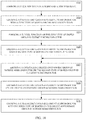
- FIG. 2 shows a method of fabricating a nanowire, in accordance with aspects of the present technology.
- FIG. 3 shows an exemplary plot of theoretical ranges of bandgap energies for different group III-V semiconductors.
- FIG. 4 shows exemplary calculated and experimental plots of the bandgap energy for GaSbN versus Sb concentrations.
- FIG. 5 shows an exemplary plot of the conduction and valence band edge position versus Sb concentration.
- FIG. 6 shows a normalized photoluminescence spectra intensity with different exemplary Sb concentrations.
- FIG. 7 shows an exemplary plot of prominent reflections of 002 in the XRD pattern for GaSbN films (left) and GaSbN nanowires (right) compared to that tor GaN.
- FIG. 8 shows an exemplary micro-Raman spectra of GaSbN films and nanowire versus Sb composition.
- FIG. 9 shows a nanowire, in accordance with aspects of the present technology.
- FIG. 10 shows a method of fabricating a nanowire, in accordance with aspects of the present technology.
- FIG. 11 shows a nanowire device, in accordance with aspects of the present technology.
- FIG. 12 shows a method of fabricating a nanowire device, in accordance with aspects of the present technology.
- FIG. 13 shows a plot of the current versus voltage (I-V characteristic) of an exemplary GaSbN at room temperature.
- FIG. 14 shows a plot of an integrated intensity (L-I characteristic) and relative external quantum efficiency (EQE) for an exemplary GaSbN LED as a function of an injection current.
- FIG. 15 shows a plot of an electroluminescence (EL) spectra (intensity) of an exemplary GaSbN LED under different pulsed biasing conditions with a 10% duty cycle at room temperature for different injection currents.
- EL electroluminescence
- routines, modules, logic blocks, and other symbolic representations of operations on data within one or more electronic devices are presented in terms of routines, modules, logic blocks, and other symbolic representations of operations on data within one or more electronic devices.
- the descriptions and representations are the means used by those skilled in the art to most effectively convey the substance of their work to others skilled in the art.
- a routine, module, logic block and or the like is herein, and generally, conceived to be a self-consistent sequence of processes or instructions leading to a desired result.
- the processes are those including physical manipulations of physical quantities.
- these physical manipulations take the form of electric or magnetic signals capable of being stored, transferred, compared and otherwise manipulated in an electronic device.
- these signals are referred to as data, bits, values, elements, symbols, characters, terms, numbers, strings, and/or the like with reference to embodiments of the present technology.
- the use of the disjunctive is intended to include the conjunctive.
- the use of definite or indefinite articles is not intended to indicate cardinality.
- a reference to “the” object or “a” object is intended to denote also one of a possible plurality of such objects.
- the use of the terms “first,” “second” and the like is not intended to specify any sort of order, instead such terms are used to differentiate elements. It is also to be understood that the phraseology and terminology used herein is for the purpose of description and should not be regarded as limiting.
- FIG. 1 shows a nanowire, in accordance with aspects of the present technology.
- the nanowire 100 can include a first semiconductor region 110 , a quantum structure 120 disposed on the first semiconductor region 110 , and a second semiconductor region 130 disposed on the quantum well structure 120 .
- the nanowire 100 can have a cylindrical, hexagonal, rectangular, triangular, or similar cross section.
- the first semiconductor region 110 can include a n-type doped group-III element semiconductor, such as Gallium Nitride (GaN).
- GaN Gallium Nitride
- the quantum well structure 120 can include a dilute-Antimonide (Sb) group-III-Nitride that includes 1% or less of Antimony (Sb)
- the second semiconductor region 130 can include a p-type doped group-III element semiconductor, such as Gallium Nitride (GaN).
- the quantum structure 120 can be a quantum active layer structure including one or more quantum layers of Gallium Antimonide Nitride (GaSbN) and Gallium Nitride (GaN).
- the quantum active layer structure 120 can include one or more quantum dots, quantum disks, quantum arch-shaped elements, quantum semi-polar planes, quantum wells, quantum dots with a shell, or similar quantum structures combinations thereof.
- the quantum active layer structure can include one or more GaSb x N 1-x /GaN quantum dot layers, wherein x is greater than 0 and equal to or less than 1%.
- the method of fabricating the nanowire can include forming a lower portion of the nanowire 110 including a n-type doped group-III element semiconductor, at 210 .
- the n-doped group-III element semiconductor can be formed by plasma-assisted molecular beam epitaxy of n-doped GaN on a n-doped silicon (Si) substrate.
- a central portion of the nanowire 120 can be formed on the lower portion of the nanowire 110 .
- the central portion of the nanowire can include a quantum well structure including a dilute-Antimonide (Sb) group-III-Nitride.
- the dilute-Antimonide (Sb) group-III-Nitride can be formed by plasma-assisted molecular beam epitaxy (MBE) of GaSb x N 1-x /GaN, wherein x is greater than 0 and equal to or less than 1%.
- an upper portion of the nanowire 130 can be formed on the central portion of the nanowire 120 .
- the upper portion of the nanowire 130 can include a p-type doped group-III element semiconductor.
- the p-doped group-III element semiconductor can be formed by plasma-assisted molecular beam epitaxy of p-doped GaN.
- either a p-doped or n-doped group-III element semiconductor can be grown first at 210 , followed by the deposition of the active region at 230 , and a n-doped or p-doped group-III element semiconductor can be grown first at 230 .
- an exemplary plot of theoretical ranges of bandgap energies for different group III-V semiconductors such as Aluminum Nitride (AlN), GaN, indium Nitride (InN), Aluminum Arsenide (AlAs) Gallium Arsenide (GaAs), Indium Arsenide (InAs), Aluminum Phosphide (AlP), Gallium Phosphide (GaP), Indium Phosphide (InP), Aluminum Antimonide (AlSb), Gallium Antimonide (GaSb) and Indium Antimonide (InSb), is shown.
- impurity levels of Antimony (Sb) and Nitride (N) with respect to the conduction band and valence band of group-III semiconductors is also shown.
- FIG. 4 exemplary calculated and experimental plots of the bandgap energy for GaSbN versus Sb concentrations is shown.
- the plots demonstrate that the energy bandgap can be controllably tuned in the dilute limit ( ⁇ 1%) for Sb.
- FIG. 5 an exemplary plot of the conduction and valence band edge position versus Sb concentration is shown.
- the band edge position for Indium Gallium Nitride (InGaN) for compositions up to 50%, are also shown.
- the plot for In x Ga 1-x N suggests that the bandgap variability would be a nearly linear change based on Sb concentration.
- concentration of Sb at or below 1% an unexpected and counterintuitive relationship between Sb concentration and the bandgap (eV) level is illustrated in the plot for GaSb x N 1-x .
- FIG. 6 a normalized photoluminescence spectra intensity, measured at 300K, for GaSbN with different exemplary Sb concentrations is shown. The concentrations were varied between 0 to 1%. The insert shows the relative constant emission intensity of GaSbN nanowire arrays.
- FIG. 7 an exemplary plot of prominent reflections of 002 in the XRD pattern for GaSbN films (left) and GaSbN nanowires (right) compared to that for GaN is shown.
- the ‘L’ and ‘H’ indicators refer to GaSbN samples with low and high Sb incorporation, respectively.
- the GaSbN nanowires grown on Si substrate can be vertically aligned on the substrate and oriented along the c-axis.
- the photoluminescence measurement was performed with a 325 nm He—Cd laser as the excitation source. Shown in FIG. 6 are the photoluminescence spectra of GaSbN obtained with different Sb concentrations into GaN.
- the Sb concentrations were varied in the range of 0% to 0.66%, which was derived based on the secondary ion mass spectroscopy (SIMS) measurements performed on GaSbN film structures grown under similar conditions. A consistent red shift with increasing Sb composition was measured, which suggests that the optical emission is not due the formation of localized defects. The estimated bandgap for different Sb incorporation is in excellent agreement with the theoretical calculation, illustrated in FIG. 7 . By further varying the epitaxy conditions, emission in the deep visible spectral range can also be achieved.
- SIMS secondary ion mass spectroscopy
- the narrower (002) peak for GaSbN nanowires shows better crystalline quality than that of GaSbN film with a broader (002) peak (FWHM approximately 1253 arcsec).
- This can be attributed to the ability for accommodating strain-relaxed growth in one-dimensional (1D) GaSbN nanowires.
- the lattice constants of the samples with high and low Sb compositions, extracted from their XRD pattern are 5.1945 (H) and 5.1897 ⁇ (L) for the films, and 5.1903 (H) and 5.1866 ⁇ (L) for the nanowires, respectively.
- FIG. 8 an exemplary micro-Raman spectra of GaSbN films and nanowire versus Sb composition is shown. Raman modes of GaN are also presented in FIG. 8 as reference, and contributions from a Si substrate are marked with an ‘*.’
- the observation can further be correlated with the room-temperature micro-Raman spectroscopy analysis of the samples.
- Micro-Raman measurements were carried out with a 514 nm argon ion laser through a 50 ⁇ objective. The focused laser spot size was approximately 1 ⁇ m and the estimated power on the sample was approximately 7 mW.
- all Raman spectra were taken in the backscattering geometry with the incident laser parallel to the hexagonal c-axis ([0001] direction) of the nanowires.
- FIG. 8 reveals the decoupling phenomenon of A 1 (LO) phonon mode from the longitudinal optical phonon-plasmon coupled (LOPC) mode, present at 740 cm ⁇ 1 in non-doped GaN.
- LO longitudinal optical phonon-plasmon coupled
- the A 1 (LO) phonon mode shifts consistently to lower frequency at increased Sb content with noticeable peak broadening.
- the additional peak (P A ) appeared at 670 cm ⁇ 1 for low Sb incorporation sample, shifts to lower frequency (667 cm ⁇ 1 ) with higher intensity as the Sb content increases in the host lattice, which can be attributed to Sb-induced local vibrational mode (LVM). This is consistent with the previous report where the additional peak and corresponding shift was observed near 650 cm ⁇ 1 for higher Sb incorporation (approximately 1-4%).
- the E 2 H mode in GaSbN film is also largely affected due to Sb incorporation, and the peak shifts significantly to lower frequency with increased FWHM for higher Sb composition.
- This peak broadening and shift is due to biaxial strain in the c-plane, induced by the disorder in atomic arrangement, which is also instructive of reduced crystalline quality.
- the Raman scattering modes in GaSbN nanowire structures are affected only slightly due to the efficient lateral surface strain relaxation, and provides better crystalline quality (narrower E 2 H peak) even at comparatively higher Sb incorporation, which can also be correlated with the lattice constants measured front XRD analysis in FIG. 7 .
- post-growth annealing can enhance the optical properties of GaSbN nanowires.
- the nanowire 900 can include a tunnel junction 905 disposed between a n-type doped group-III element semiconductor 910 and a p-type doped group-III element semiconductor 915 .
- the n-type doped group-III element semiconductor 910 can include n-type doped Gallium Nitride (GaN)
- the p-type doped group-III element semiconductor 915 can be p-type doped Gallium Nitride (GaN).
- the tunnel junction 905 can include an aluminum (Al) layer disposed between a heavily n-type doped Gallium Nitride (n ++ GaN) and a heavily p-type doped Gallium Nitride (p ++ GaN) .
- the tunnel junction 905 can include a heavily n-type doped Gallium Nitride (n ++ GaN) disposed on a heavily p-type doped Gallium Nitride (p ++ GaN).
- the tunnel junction 905 can include an Indium Gallium Nitride (InGaN) layer disposed between a heavily n-type doped Gallium Nitride (n ++ GaN) and a heavily p-type doped Gallium Nitride (p ++ GaN).
- the tunnel junction 905 can be configured to improve the efficiency of the optoelectronic nanowires.
- the nanowire 900 can further include a quantum structure 925 - 960 disposed between the p-type doped group-III element semiconductor 915 and another n-type doped group-III element semiconductor 970 .
- the quantum structure 925 - 960 can include one or more quantum dots.
- a quantum dot can include a layer of Gallium Nitride (GaN), 920 disposed on a dilute-Antimonide (Sb) group-III-Nitride, 925 .
- the quantum layers 920 - 965 can be GaSbN/GaN quantum dot layers (also commonly referred to as “dot-in” nanowires). While quantum dot layers are shown in the illustrated example, the GaSbN/GaN quantum layers can be formed of quantum dots, quantum disks, quantum arch-shaped structures, quantum semi-polar planes, quantum wells, quantum dots in a shell, or other similar quantum structures or combination thereof.
- the nanowire 900 can have a cylindrical, hexagonal, rectangular, triangular, or similar cross section. Each nanowire 900 can be a quantum active region LED.
- the dilute-Antimonide quantum active layer structure can exhibit a strong photoluminescence emission at room temperature.
- the emission output can be tuned from approximately 3.4 to 2.0 electron Volts (eV) through controlled Antimony (Sb) into the nanowire heterostructures.
- the nanowire can therefore output light in the deep visible wavelengths (e.g., green).
- the tunability of the emission output can be based on the formation of valance band states, rather than localized defect states.
- the method of fabrication can include forming nucleation sites on a substrate, at 1005 .
- a Ga-seeding layer (approximately 1 monolayer) can be used for the nucleation of nanowires.
- a crystalline group-III element semiconductor with a first type of doping 910 can be grown on the nucleation sites on the substrate, at 1010 .
- a n-type doped Gallium Nitride (GaN) layer can be epitaxial grown on a n-type doped silicon substrate.
- Germanium (Ge) can be used for the n-type dopant.
- a tunnel junction can be formed on the first type of doped group-III element semiconductor 910 .
- a heavily n-type doped group-III element semiconductor such as heavily n-type doped Gallium Nitride (n ++ GaN)
- n ++ GaN can be epitaxially deposited on the n-type doped Gallium Nitride (GaN).
- a thin conductive layer such as an Aluminum (Al), can be deposited on the heavily n-type doped Gallium Nitride (n ++ GaN).
- a thin Gallium (Ga) seed layer can be deposited at a low temperature on the Al layer, and then a heavily p-type doped Gallium Nitride (p ++ GaN) can be deposited on the seed layer to form a tunnel junction 905 .
- the tunnel junction can include a heavily n-type doped Gallium Nitride (n ++ GaN) disposed on a heavily p-type doped Gallium Nitride (p ++ GaN), an indium Gallium Nitride (InGaN) layer disposed between a heavily n-type doped Gallium Nitride (n ++ GaN) and a heavily p-type doped Gallium Nitride (p ++ GaN), or any other applicable tunnel junction structure.
- a crystalline group-III element semiconductor with a second type of doping 915 can be grown on the tunnel junction 905 .
- a p-type doped Gallium Nitride (GaN) layer can be epitaxially grown on the heavily p-type doped Gallium Nitride (p ++ GaN) of the tunnel junction 905 .
- Magnesium (Mg) can be used for the p-type dopant.
- a dilute-Antimonide (Sb) group-III-Nitride semiconductor 925 can be grown on the second type of doped group-III element semiconductor 915 .
- a Gallium Antimonide Nitride (GaSbN) layer can be epitaxial grown on the p-type doped Gallium Nitride (GaN) layer to form a quantum dot.
- a group-III element semiconductor 920 can be grown on the dilute-Antimonide (Sb) group-III-Nitride semiconductor 925 .
- a substantially intrinsic Gallium Nitride (GaN) layer can be epitaxially grown.
- the Antimony (Sb) can be incorporated at a concentration of 1% or less.
- the GaSbN layer can be deposited using molecular beam epitaxy with a radio frequency plasma-assisted nitrogen source.
- the growth can be performed on a n-type Si substrate with a (111) lattice structure orientation, without external catalyst.
- a Ga-seeding layer (approximately 1 monolayer) can be used for the nucleation of nanowires.
- GaN-based heterostructures are conventionally grown at relatively high temperatures (e.g., 700° C.). However, controlled Sb incorporation at such high temperatures can be challenging due to the large Sb surface desorption and segregation.
- Sb can be controllably incorporated in GaN at intermediate growth temperatures.
- growth parameters tor GaSbN nanowires can include substrate temperatures in the range of 650 to 705° C., Ga beam equivalent pressure of approximately 4 ⁇ 10 ⁇ 8 Torr, and Sb beam equivalent pressure in the range of approximately 5 ⁇ 10 ⁇ 10 to 1 ⁇ 10 ⁇ 7 Torr.
- the nitrogen plasma power can be approximately 350 Watts and the nitrogen flow rate can be in the range of 0.3-0.5 standard cubic centimeter per minute (sccm).
- the processes at 1020 and 1030 can be performed one or more times to form a quantum structure including one or more quantum dots.
- the processes at 1025 and 1030 can be iteratively performed five times to form a quantum structure including five quantum dots as illustrated in FIG. 9 .
- the illustrated example is not intended to be limiting.
- the nanowire in accordance with aspects of the present technology can be fabricated with any number of quantum dots or other multi-quantum structure.
- a crystalline group-III element semiconductor with the first type of doping 970 can be grown on the upper most group-III element semiconductor 960 .
- a n-type doped Gallium Nitride (GaN) layer can be epitaxially grown on the substantially intrinsic Gallium Nitride (GaN) layer 960 .
- the nanowire device can include one or more clusters of nanowires 900 disposed on a substrate 1105 .
- the nanowires can have a structure as described above with regard to FIGS. 1 and 9 .
- different clusters of nanowires 900 can have different concentrations of dilute-Antimonide to reduce the bandgap energy by different amounts in different clusters of the nanowires 900 .
- the different concentrations of dilute-Antimonide can result in different optical emissions within a range of 365 to 600 nanometers (nm) for the different clusters of nanowires.
- the nanowires in one or more clusters can have different concentrations of dilute-Antimonide a multi-colored solid-state light source.
- One or more first contacts 1110 - 1120 can be disposed on the one or more cluster of nanowires 900 opposite the substrate 1105 .
- a plurality of first contacts 1110 - 1120 can be configured to couple to different clusters of nanowires 900 .
- FIG. 11 illustrates a single first contact 1110 - 1120 configured to be coupled to a cluster of twenty-five nanowires 900 .
- the device can include one or more sets of clusters of nanowires 900 with corresponding separate first contacts 1110 - 1120 .
- the one or more first contacts 1110 - 1120 can include a first layer 1110 of Nickle (Ni), Gold (Au) and/or NiAu alloys thereof, a second layer 1115 of Indium Tin Oxide (ITO) disposed on the first layer 1110 and coupled to the plurality of nanowires 900 , and a third layer 1120 of Nickle (Ni), Gold (Au) and/or NiAu alloys thereof disposed on the second layer 1115 .
- the second layer 1115 of ITO can be configured to permit light to pass through.
- the first and third layers 1110 , 1120 can be configured to make good ohmic contact with the nanowires 900 through the second layer 1115 , and can include one or more windows to permit light to pass through.
- the nanowires device can further include an optically transmissive layer 1125 disposed about the one or more clusters of nanowires 900 between the substrate and the one or more first contacts 1110 - 1120 .
- the optically transmissive layer 1125 can be a polyimide.
- One or more second contacts 1130 can be disposed on the substrate 1105 opposite the one or more clusters of nanowires 900 .
- the one or more second contacts 1130 can be electrically coupled to the nanowires 900 through the substrate 1105 .
- the one or snore second contacts 1130 can include one or more layers of Titanium (Ti), Gold (Au) and/or TiAu alloys thereof.
- the substrate 1105 can be a heavily n-doped silicon (Si) substrate to make a good ohmic contact between the second contact 1130 and the one or more clusters of nanowires 900 .
- the method of fabrication can include forming one or more clusters of nanowires on a substrate, 1205 .
- the nanowires can be formed on the substrate as described above with regard to FIGS. 2 and 10 .
- an optically transmissive insulator layer can be conformally deposited on the substrate about the one or more clusters of nanowires.
- the insulator layer can be an optically transmissive polyimide layer.
- the insulative layer can be planarized, wherein tops of the one or more clusters of nanowires are exposed and the optically transmissive insulative layer is disposed between the one or more clusters of nanowires.
- a first set of one or more layers of a first contact can be deposited on the planarized surface of the optically transmissive insulator layer and the exposed tops of the one or more clusters of nanowires.
- the first set of one or more layers of the first contact can be electrically coupled to the one or more clusters of nanowires.
- a first layer of Nickle, Gold and/or alloys thereof can be deposited on the optically transmissive insulator layer and the exposed tops of the one or more clusters of nanowires.
- the first layer of Nickle (Ni), Gold (Au) and/or NiAu alloys thereof can be deposited as a very thin film that is configured to be substantially optically transmissive.
- a masking and selective etching process can be used to form one or more windows through the first layer of Nickle, Gold and/or alloys thereof.
- An Indium Fin Oxide (ITO) layer can be deposited on the first layer of Nickle (Ni), Gold (Au) and/or NiAu alloys thereof.
- the ITO layer can be configured to be optically transmissive.
- a second layer can be deposited on the ITO layer.
- a masking and selective etching process can be used to form one or more windows through the second layer of Nickle (Ni), Gold (Au) and/or NiAu alloys thereof.
- a second contact can be deposited on the substrate opposite the one or more clusters of nanowires, the optically transmissive insulator layer and first contact.
- a layer of Titanium (Ti), Gold (Au) and/or TiAu alloys thereof can be deposited on the substrate to form the second contact.
- FIG. 13 a plot of the current versus voltage (I-V characteristic) of an exemplary GaSbN at room temperature is shown.
- the inset shows a 45° tilted scanning electron microscope (SEM) image of an exemplary as grown GaSbN dot-in nanowire cluster (wherein the scale bar represents 1 micrometer ( ⁇ m)).
- SEM scanning electron microscope
- FIG. 14 a plot of an integrated intensity (L-I characteristic) and relative external quantum efficiency (EQE) for an exemplary GaSbN LED as a function of an injection current is shown.
- FIG. 15 a pot of an electroluminescence (EL) spectra (intensity) of an exemplary GaSbN LED under different pulsed biasing conditions with a 10% duty cycle at room temperature for different injection currents is shown.
- EL electroluminescence
- strong quantum confinement was achieved in GaSbN/GaN quantum wells/dots with Sb concentration ⁇ 1% in the active region.
- the degree of quantum confinement and the emission wavelengths can be varied through controlled Sb incorporation.
- a plurality of GaSbN (3 nm)/GaN (3 nm) quantum dots can be incorporated along the growth direction in the active region in a manner.
- the quantum dot active region was grown at relatively low substrate temperature of approximately 650° C. Other growth conditions are similar to those described for the GaSbN nanowire structures.
- a n ++ -GaN/Al/p ++ -GaN tunnel junction (TJ) were incorporated into the LED structure illustrated in FIG. 9 .
- the scanning electron microscope (SEM) image, in the inset in FIG. 13 reveals the growth of vertically aligned GaSbN dot-in-nanowire arrays with relatively high uniformity and areal density.
- the incorporation of a very small amount of Sb (>1%) in GaN can substantially reduce the energy bandgap of GaN from approximately 3.4 to 2 eV.
- concentration of Sb in the GaN can adjust the wavelength of the optical emission from approximately 365 to 600 nm at room temperature.
- Gallium Antimonide Nitride (GaSbN) nanowires and optoelectronic devices incorporating GaSbN nanowires exhibit strong photoluminescence emission within room temperature ranges. Furthermore, the emission output can be tuned from approximately 3.4 eV to approximated 2.0 eV through incorporating Antimony (Sb) into the heterostructures of the nanowire.
- Nanowires incorporating dilute-Sb group-III nitrides into quantum structures can operate in the deep visible range, and therefore can advantageously be utilized in high efficiency optoelectronic, photonic, and solar energy devices.
Landscapes
- Led Devices (AREA)
Abstract
Description
Claims (21)
Priority Applications (1)
| Application Number | Priority Date | Filing Date | Title |
|---|---|---|---|
| US16/030,855 US10727372B2 (en) | 2017-07-07 | 2018-07-09 | Dilute-Antimonide group-III-Nitride nanostructure optoelectronic devices |
Applications Claiming Priority (2)
| Application Number | Priority Date | Filing Date | Title |
|---|---|---|---|
| US201762529915P | 2017-07-07 | 2017-07-07 | |
| US16/030,855 US10727372B2 (en) | 2017-07-07 | 2018-07-09 | Dilute-Antimonide group-III-Nitride nanostructure optoelectronic devices |
Publications (2)
| Publication Number | Publication Date |
|---|---|
| US20190013440A1 US20190013440A1 (en) | 2019-01-10 |
| US10727372B2 true US10727372B2 (en) | 2020-07-28 |
Family
ID=64902853
Family Applications (1)
| Application Number | Title | Priority Date | Filing Date |
|---|---|---|---|
| US16/030,855 Active US10727372B2 (en) | 2017-07-07 | 2018-07-09 | Dilute-Antimonide group-III-Nitride nanostructure optoelectronic devices |
Country Status (1)
| Country | Link |
|---|---|
| US (1) | US10727372B2 (en) |
Families Citing this family (6)
| Publication number | Priority date | Publication date | Assignee | Title |
|---|---|---|---|---|
| US10290768B2 (en) * | 2017-09-14 | 2019-05-14 | Globalfoundries Inc. | Nanowire formation methods |
| US20230033526A1 (en) * | 2019-12-24 | 2023-02-02 | The Regents Of The University Of Michigan | Group iii-nitride excitonic heterostructures |
| EP4107791A4 (en) * | 2020-02-18 | 2024-03-13 | The Regents of The University of Michigan | Micrometer scale light-emitting diodes |
| JP7485278B2 (en) * | 2020-03-09 | 2024-05-16 | セイコーエプソン株式会社 | Light emitting device and projector |
| JP7638489B2 (en) * | 2021-02-01 | 2025-03-04 | 豊田合成株式会社 | Semiconductor device and method for manufacturing the same |
| CN117321785A (en) * | 2021-05-14 | 2023-12-29 | 密歇根大学董事会 | High efficiency InGaN light emitting diodes |
Citations (1)
| Publication number | Priority date | Publication date | Assignee | Title |
|---|---|---|---|---|
| US20180261455A1 (en) * | 2015-10-20 | 2018-09-13 | King Abdullah University Of Science And Technology | Nanowires-based light emitters on thermally and electrically conductive substrates and of making same |
-
2018
- 2018-07-09 US US16/030,855 patent/US10727372B2/en active Active
Patent Citations (1)
| Publication number | Priority date | Publication date | Assignee | Title |
|---|---|---|---|---|
| US20180261455A1 (en) * | 2015-10-20 | 2018-09-13 | King Abdullah University Of Science And Technology | Nanowires-based light emitters on thermally and electrically conductive substrates and of making same |
Non-Patent Citations (1)
| Title |
|---|
| Murdin et al., "Dilute Antimonide Nitrides for very long wavelength infared applications", Procedings of SPIE, Jan. 2006, pp. 1-8. * |
Also Published As
| Publication number | Publication date |
|---|---|
| US20190013440A1 (en) | 2019-01-10 |
Similar Documents
| Publication | Publication Date | Title |
|---|---|---|
| US10727372B2 (en) | Dilute-Antimonide group-III-Nitride nanostructure optoelectronic devices | |
| Royo et al. | A review on III–V core–multishell nanowires: growth, properties, and applications | |
| Zhao et al. | Aluminum nitride nanowire light emitting diodes: Breaking the fundamental bottleneck of deep ultraviolet light sources | |
| Morkoç | Nitride semiconductors and devices | |
| US8314415B2 (en) | Radiation-emitting semiconductor body | |
| Guo et al. | Catalyst-free InGaN/GaN nanowire light emitting diodes grown on (001) silicon by molecular beam epitaxy | |
| Le et al. | Carriers capturing of V-defect and its effect on leakage current and electroluminescence in InGaN-based light-emitting diodes | |
| US20170323788A1 (en) | Metal based nanowire tunnel junctions | |
| US20100187550A1 (en) | Light emitting diode | |
| Jiang et al. | AlGaN and InAlGaN alloys-epitaxial growth, optical and electrical properties, and applications | |
| Pandey et al. | An AlGaN tunnel junction light emitting diode operating at 255 nm | |
| US10665451B2 (en) | Nanowires-based light emitters on thermally and electrically conductive substrates and of making same | |
| Kapoor et al. | Green electroluminescence from radial m-plane InGaN quantum wells grown on GaN wire sidewalls by metal–organic vapor phase epitaxy | |
| Bavencove et al. | Light emitting diodes based on GaN core/shell wires grown by MOVPE on n-type Si substrate | |
| Zhao et al. | AlGaN nanowires: path to electrically injected semiconductor deep ultraviolet lasers | |
| Liang et al. | Heavy Mg-doping of (Al, Ga) N films for potential applications in deep ultraviolet light-emitting structures | |
| Yadav et al. | Electroluminescence study of InGaN/GaN QW based pin and inverted pin junction based short-wavelength LED device using laser MBE technique | |
| Sadaf et al. | Structural and electrical characterization of monolithic core–double shell n-GaN/Al/p-AlGaN nanowire heterostructures grown by molecular beam epitaxy | |
| Lysov et al. | Optical properties of heavily doped GaAs nanowires and electroluminescent nanowire structures | |
| US9331237B2 (en) | Semiconductor light emitting device, including a plurality of barrier layers and a plurality of well layers, and method for manufacturing the same | |
| JP2010526444A (en) | Light emitting diode device layer structure using indium gallium nitride contact layer | |
| US20250194300A1 (en) | Light emitting devices and methods of manufacture | |
| Gustafsson et al. | From InGaN pyramids to micro-LEDs characterized by cathodoluminescence | |
| Hasan et al. | Effects of InGaN quantum disk thickness on the optical properties of GaN nanowires | |
| Shi et al. | Photoluminescence properties of InGaN/GaN multiple quantum wells containing a gradually changing amount of indium in each InGaN well layer along the growth direction |
Legal Events
| Date | Code | Title | Description |
|---|---|---|---|
| FEPP | Fee payment procedure |
Free format text: ENTITY STATUS SET TO UNDISCOUNTED (ORIGINAL EVENT CODE: BIG.); ENTITY STATUS OF PATENT OWNER: LARGE ENTITY |
|
| STPP | Information on status: patent application and granting procedure in general |
Free format text: DOCKETED NEW CASE - READY FOR EXAMINATION |
|
| AS | Assignment |
Owner name: THE REGENTS OF THE UNIVERSITY OF MICHIGAN, MICHIGAN Free format text: ASSIGNMENT OF ASSIGNORS INTEREST;ASSIGNORS:CHOWDHURY, MOHAMMAD FAQRUL ALAM;MI, ZETIAN;REEL/FRAME:048004/0920 Effective date: 20181129 Owner name: THE REGENTS OF THE UNIVERSITY OF MICHIGAN, MICHIGA Free format text: ASSIGNMENT OF ASSIGNORS INTEREST;ASSIGNORS:CHOWDHURY, MOHAMMAD FAQRUL ALAM;MI, ZETIAN;REEL/FRAME:048004/0920 Effective date: 20181129 |
|
| STPP | Information on status: patent application and granting procedure in general |
Free format text: NON FINAL ACTION MAILED |
|
| STPP | Information on status: patent application and granting procedure in general |
Free format text: RESPONSE TO NON-FINAL OFFICE ACTION ENTERED AND FORWARDED TO EXAMINER |
|
| STPP | Information on status: patent application and granting procedure in general |
Free format text: NON FINAL ACTION MAILED |
|
| STPP | Information on status: patent application and granting procedure in general |
Free format text: NOTICE OF ALLOWANCE MAILED -- APPLICATION RECEIVED IN OFFICE OF PUBLICATIONS |
|
| STPP | Information on status: patent application and granting procedure in general |
Free format text: NOTICE OF ALLOWANCE MAILED -- APPLICATION RECEIVED IN OFFICE OF PUBLICATIONS |
|
| STPP | Information on status: patent application and granting procedure in general |
Free format text: PUBLICATIONS -- ISSUE FEE PAYMENT VERIFIED |
|
| STCF | Information on status: patent grant |
Free format text: PATENTED CASE |
|
| MAFP | Maintenance fee payment |
Free format text: PAYMENT OF MAINTENANCE FEE, 4TH YEAR, LARGE ENTITY (ORIGINAL EVENT CODE: M1551); ENTITY STATUS OF PATENT OWNER: LARGE ENTITY Year of fee payment: 4 |