US10724605B2 - Main drive device of planocentric set - Google Patents
Main drive device of planocentric set Download PDFInfo
- Publication number
- US10724605B2 US10724605B2 US16/100,998 US201816100998A US10724605B2 US 10724605 B2 US10724605 B2 US 10724605B2 US 201816100998 A US201816100998 A US 201816100998A US 10724605 B2 US10724605 B2 US 10724605B2
- Authority
- US
- United States
- Prior art keywords
- planocentric
- rolling
- shaft
- outer ring
- speed
- Prior art date
- Legal status (The legal status is an assumption and is not a legal conclusion. Google has not performed a legal analysis and makes no representation as to the accuracy of the status listed.)
- Expired - Fee Related, expires
Links
Images


Classifications
-
- F—MECHANICAL ENGINEERING; LIGHTING; HEATING; WEAPONS; BLASTING
- F16—ENGINEERING ELEMENTS AND UNITS; GENERAL MEASURES FOR PRODUCING AND MAINTAINING EFFECTIVE FUNCTIONING OF MACHINES OR INSTALLATIONS; THERMAL INSULATION IN GENERAL
- F16H—GEARING
- F16H1/00—Toothed gearings for conveying rotary motion
- F16H1/28—Toothed gearings for conveying rotary motion with gears having orbital motion
- F16H1/32—Toothed gearings for conveying rotary motion with gears having orbital motion in which the central axis of the gearing lies inside the periphery of an orbital gear
-
- B—PERFORMING OPERATIONS; TRANSPORTING
- B60—VEHICLES IN GENERAL
- B60K—ARRANGEMENT OR MOUNTING OF PROPULSION UNITS OR OF TRANSMISSIONS IN VEHICLES; ARRANGEMENT OR MOUNTING OF PLURAL DIVERSE PRIME-MOVERS IN VEHICLES; AUXILIARY DRIVES FOR VEHICLES; INSTRUMENTATION OR DASHBOARDS FOR VEHICLES; ARRANGEMENTS IN CONNECTION WITH COOLING, AIR INTAKE, GAS EXHAUST OR FUEL SUPPLY OF PROPULSION UNITS IN VEHICLES
- B60K17/00—Arrangement or mounting of transmissions in vehicles
- B60K17/04—Arrangement or mounting of transmissions in vehicles characterised by arrangement, location or kind of gearing
-
- B—PERFORMING OPERATIONS; TRANSPORTING
- B64—AIRCRAFT; AVIATION; COSMONAUTICS
- B64D—EQUIPMENT FOR FITTING IN OR TO AIRCRAFT; FLIGHT SUITS; PARACHUTES; ARRANGEMENT OR MOUNTING OF POWER PLANTS OR PROPULSION TRANSMISSIONS IN AIRCRAFT
- B64D35/00—Transmitting power from power plants to propellers or rotors; Arrangements of transmissions
- B64D35/02—Transmitting power from power plants to propellers or rotors; Arrangements of transmissions specially adapted for specific power plants
-
- H—ELECTRICITY
- H02—GENERATION; CONVERSION OR DISTRIBUTION OF ELECTRIC POWER
- H02K—DYNAMO-ELECTRIC MACHINES
- H02K7/00—Arrangements for handling mechanical energy structurally associated with dynamo-electric machines, e.g. structural association with mechanical driving motors or auxiliary dynamo-electric machines
- H02K7/006—Structural association of a motor or generator with the drive train of a motor vehicle
-
- H—ELECTRICITY
- H02—GENERATION; CONVERSION OR DISTRIBUTION OF ELECTRIC POWER
- H02K—DYNAMO-ELECTRIC MACHINES
- H02K7/00—Arrangements for handling mechanical energy structurally associated with dynamo-electric machines, e.g. structural association with mechanical driving motors or auxiliary dynamo-electric machines
- H02K7/10—Structural association with clutches, brakes, gears, pulleys or mechanical starters
- H02K7/116—Structural association with clutches, brakes, gears, pulleys or mechanical starters with gears
-
- H—ELECTRICITY
- H02—GENERATION; CONVERSION OR DISTRIBUTION OF ELECTRIC POWER
- H02K—DYNAMO-ELECTRIC MACHINES
- H02K7/00—Arrangements for handling mechanical energy structurally associated with dynamo-electric machines, e.g. structural association with mechanical driving motors or auxiliary dynamo-electric machines
- H02K7/18—Structural association of electric generators with mechanical driving motors, e.g. with turbines
- H02K7/1807—Rotary generators
- H02K7/1846—Rotary generators structurally associated with wheels or associated parts
-
- B—PERFORMING OPERATIONS; TRANSPORTING
- B61—RAILWAYS
- B61C—LOCOMOTIVES; MOTOR RAILCARS
- B61C9/00—Locomotives or motor railcars characterised by the type of transmission system used; Transmission systems specially adapted for locomotives or motor railcars
- B61C9/38—Transmission systems in or for locomotives or motor railcars with electric motor propulsion
-
- B—PERFORMING OPERATIONS; TRANSPORTING
- B63—SHIPS OR OTHER WATERBORNE VESSELS; RELATED EQUIPMENT
- B63H—MARINE PROPULSION OR STEERING
- B63H23/00—Transmitting power from propulsion power plant to propulsive elements
- B63H23/02—Transmitting power from propulsion power plant to propulsive elements with mechanical gearing
- B63H2023/0283—Transmitting power from propulsion power plant to propulsive elements with mechanical gearing using gears having orbital motion
-
- B—PERFORMING OPERATIONS; TRANSPORTING
- B63—SHIPS OR OTHER WATERBORNE VESSELS; RELATED EQUIPMENT
- B63H—MARINE PROPULSION OR STEERING
- B63H23/00—Transmitting power from propulsion power plant to propulsive elements
- B63H23/02—Transmitting power from propulsion power plant to propulsive elements with mechanical gearing
-
- F—MECHANICAL ENGINEERING; LIGHTING; HEATING; WEAPONS; BLASTING
- F03—MACHINES OR ENGINES FOR LIQUIDS; WIND, SPRING, OR WEIGHT MOTORS; PRODUCING MECHANICAL POWER OR A REACTIVE PROPULSIVE THRUST, NOT OTHERWISE PROVIDED FOR
- F03D—WIND MOTORS
- F03D15/00—Transmission of mechanical power
-
- F—MECHANICAL ENGINEERING; LIGHTING; HEATING; WEAPONS; BLASTING
- F05—INDEXING SCHEMES RELATING TO ENGINES OR PUMPS IN VARIOUS SUBCLASSES OF CLASSES F01-F04
- F05B—INDEXING SCHEME RELATING TO WIND, SPRING, WEIGHT, INERTIA OR LIKE MOTORS, TO MACHINES OR ENGINES FOR LIQUIDS COVERED BY SUBCLASSES F03B, F03D AND F03G
- F05B2260/00—Function
- F05B2260/40—Transmission of power
- F05B2260/403—Transmission of power through the shape of the drive components
- F05B2260/4031—Transmission of power through the shape of the drive components as in toothed gearing
- F05B2260/40311—Transmission of power through the shape of the drive components as in toothed gearing of the epicyclic, planetary or differential type
Definitions
- the present invention relates to a mechanical drive device, and in particular, to a drive element that is used in a drive device of a planocentric set and that can directly transfer power to a planet wheel; and specifically, to a main drive device of a planocentric set that is mainly applied to three armed forces equipment for decelerating or accelerating a speed at a high speed ratio.
- a pure inner engaging pair of a planocentric set has an obvious advantage of a small contact stress, which is usually smaller than 10 kg/mm 2 .
- a contact stress of a corresponding outer engaging pair is approximately 100 kg/mm 2 (a double-gear NGW accelerator in a 750-KW natural wind turbine).
- a relationship between a contact stress of a gear and a service life of a gear surface is approximately that when the contact stress is reduced by one time, the service is increased by 100 times. This is equivalent to that a service life contrast of inner engaging to outer engaging at the same condition is approximately 10 to the 3.2 th power.
- a service life contrast of inner engaging to outer engaging at the same condition is approximately 10 to the 3.2 th power.
- noise of a reducer is level 80 ⁇ 85 dB
- noise of an engaging pair of a planocentric set is approximately 65 dB to 70 dB.
- a rolling shaft only has a function of bearing a centric (shaft) stress, but does not have a function of transferring a torque between an inner ring and an outer ring.
- a NEW externally engaged pair used in a reducer of a separate electrically-driven device in an automobile wheel has such disadvantages as a large externally-engaged contact stress, high noise, and a short service life.
- An NGW or an externally engaged parallel-shaft device used by a main drive device in a ship or a warship in the prior art has disadvantages of high noise, a large engaged contact stress, a multilevel and large volume.
- a double-gear NGW externally engaged pair only used by an existing natural wind accelerator has many foregoing disadvantages and shortcomings.
- a torque cannot be transferred and no buffer device exists between an inner ring and an outer ring of an arm bearing of a planocentric set pair.
- an externally engaged pair is used for main drive, and no buffer device is configured.
- a conventional automobile is started by using a hydraulic converter, there is no buffer facility for driving of an electrically-powered automobile, a system shape change amount of positive driving is limited, and a compelling force is larger than that of a resilient buffer structure in the present invention by dozens of times.
- an objective of the present invention is to design a rolling bearing type main drive device that can cancel an existing driving structure, directly use planet wheel bearing drive power, and drive an inner ring and an outer ring of the planet wheel to transfer a torque.
- a main drive device of a planocentric set for three armed forces installed on a bearing position of a planocentric set planet wheel, and directly transferring power of a prime mover to the planet wheel to drive the planet wheel to implement differential rotation
- the main drive device of a planocentric set for three armed forces mainly includes an inner ring 7 , an outer ring 6 , a rolling column 4 , and rolling pin shaft pairs 13 ;
- the inner ring 7 is installed on an eccentric shaft 11 and rotates driven by the eccentric shaft 11 ;
- the eccentric shaft 11 is driven by the prime mover;
- the rolling column 4 is installed between the inner ring 7 and the outer ring 6 and at a side closer to the inner ring 7 ;
- the rolling pin shaft pair 13 is installed between the inner ring 7 and the outer ring 6 and at a side closer to the outer ring 6 ; when the rolling column 4 is in contact with the inner ring 7 to transfer the power, the rolling column 4 is in contact with one of the two neighboring rolling pin shaft pairs 13
- the rolling pin shaft pair 13 includes a pin shaft 8 and a cycle of equispaced rolling pins 5 that are disposed in a cylinder 10 and in contact with the cylinder 10 , an inner edge of the rolling pin 5 is in contact with an outer edge of the pin shaft 8 , and two terminal shafts 9 of the pin shaft 8 are disposed in open pores at two ends of the outer ring 6 .
- the inner ring 7 is installed on the eccentric shaft 11 through interference fit.
- the inner ring 7 is connected to the eccentric shaft 11 by using an active key 17 , a passive key 18 , and springs 16 , the active key 17 is fixed on the eccentric shaft 11 , the passive key 18 is fixed on the inner ring 7 , and two ends of each of the two springs 16 are respectively connected to two side surfaces of the active key 17 and two side surfaces of the passive key 18 , to implement buffer driving between the eccentric shaft 11 and the inner ring, as shown in FIG. 12 .
- a main drive device of a planocentric set for three armed forces where the main drive device of a planocentric set for three armed forces mainly includes an inner ring 7 , an outer ring 6 , a rolling column 4 , and rolling pin shaft pairs 13 ;
- the inner ring 7 is installed on an eccentric shaft 11 ;
- the rolling column 4 is installed between the inner ring 7 and the outer ring 6 and at a side closer to the outer ring 6 ;
- the rolling pin shaft pair 13 is installed between the inner ring 7 and the outer ring 6 and at a side closer to the inner ring 7 ;
- the outer ring 6 is connected to a spoke 3 of a planocentric set planet wheel, and drives the rolling column 4 to rotate; when the rolling column 4 is in contact with the outer ring 6 to transfer power, the rolling column 4 is in contact with one of the two rolling pin shaft pairs 13 to transmit the power to the rolling pin shaft pairs 13 in clockwise rotation and counter-clockwise rotation; the rolling pin shaft pair 13 drives the inner ring 7
- the rolling pin shaft pair 13 includes a pin shaft 8 and a cycle of equispaced rolling pins 5 that are disposed in a cylinder 10 and in contact with the cylinder 10 , an inner edge of the rolling pin 5 is in contact with an outer edge of the pin shaft 8 , and two terminal shafts 9 of the pin shaft 8 are disposed in open pores at two ends of the outer ring 6 .
- the outer ring 6 is connected to the spoke 3 of the planocentric set planet wheel through interference fit.
- the outer ring 6 is connected to the spoke 3 of the planocentric set planet wheel by using an active key 17 , a passive key 18 , and springs 16 ;
- the active key 17 is fixed on the spoke 3 of the planocentric set planet wheel,
- the passive key 18 is fixed on the outer ring 6 , and two ends of each of the two springs 16 are respectively connected to two side surfaces of the active key 17 and two side surfaces of the passive key 18 , to implement buffer driving between the spoke 3 and the outer ring 6 .
- a speed deceleration device powered by a high-frequency high-speed alternating electromotor having a hollow rotor shaft, or a motor that uses a hollow coaxial shaft 26 as a union body and is loaded with a spoke of a rolling bearing-type automobile/armored vehicle, or driven by a gasoline/diesel machine;
- an electrically device applied to an electrically hub of a planocentric set of an automobile having two gears of speed, formed by a friction pair driven by an inner-and-outer ring electromagnet formed by a hollow coaxial shaft 26 and a radial component of an external diameter of an inner gear ring;
- a rolling bearing device applied to a planocentric set at an eccentric wheel position of an engaging pair of a cycloidal pin wheel.
- a torque may be transferred between an inner ring 7 and an outer ring 6 , and a spring 16 having stretching and compression performance is disposed between the inner ring 7 and the eccentric shaft 11 .
- the pin shaft pairs 13 include a pin shaft 8 and a cycle of equispaced rolling pins 5 that are disposed in a cylinder 10 and in contact with the cylinder 10 .
- An inner edge of the rolling pin 5 is in contact with an outer edge of the pin shaft 8 , and two terminal shafts 9 of the pin shaft 8 are disposed in -shaped open pores at two ends of the outer ring 6 .
- An outer edge of the rolling column 4 is respectively in contact with an outer edge of the cylinder 10 in each of the left and the right rolling pin shaft pair 13 .
- An inner edge of the rolling column 4 is in contact with an outer edge of the inner ring 7 .
- Two springs 16 are disposed at each of the two ends of the eccentric shaft 11 in the inner ring 7 .
- Two ends of the springs 16 are fixedly connected to the keys 17 and 18 , to form a speed deceleration device of a planocentric set or a cycloidal pin wheel that uses the inner ring 7 as an active member, has buffer performance and is loaded with a rolling bearing pair.
- the pin shaft pairs 13 include a pin shaft 8 and a cycle of equispaced rolling pins 5 that are disposed in a cylinder 10 and in contact with the cylinder 10 .
- An inner edge of the rolling pin 5 is in contact with an outer edge of the pin shaft 8 , and two terminal shafts 9 of the pin shaft 8 are disposed in -shaped open pores at two ends of the inner ring 7 .
- An inner edge of the rolling column 4 is respectively in contact with an outer edge of the cylinder 10 in each of the left and the right rolling pin shaft pair 13 .
- An outer edge of the rolling column 4 is in contact with an inner edge of the inner ring 7 .
- Two springs 16 are disposed at two ends of the outer ring 6 and the spoke 3 . Two ends of the springs 16 are fixedly connected to the keys 17 and 18 , to form a speed acceleration device of a planocentric set or a cycloidal pin wheel that uses the planet wheel spoke 3 and the outer ring 6 as active members, has buffer performance and is loaded with a rolling bearing pair.
- the loaded rolling bearing pair may be a structure that purely transfer a torque but does not have a buffer spring, or may be a structure that can both transfer a torque and has a buffer spring.
- the rolling columns 4 are evenly disposed at a radial outer edge of the vehicle inner ring 7 , the outer edge of the rolling column 4 is respectively in contact with an outer edge of the left and right cylinder 10 , and the terminal shafts 9 are disposed in -shaped open pores at two ends of the outer ring 6 .
- the rolling columns 4 are evenly installed on the inner radial circumference of the outer ring 6 and the rolling columns 4 are respectively in contact with the outer edge of the left and right cylinder 10 .
- the shaft end 9 of the rolling pin shaft pair is installed in -shaped open pores at two ends of the inner ring 7 .
- the outer ring 6 of the loaded rolling bearing pair is installed at the center of a planet wheel spoke in a planocentric set or a cycloidal pin wheel engaging pair having an eccentric wheel 11 .
- the planocentric set engaging pair or a cycloidal pin wheel engaging pair loaded with a rolling bearing does not need to be provided with a most compact engaging pair of highest efficiency of an output mechanism.
- the planocentric set engaging pair and the cycloidal pin wheel engaging pair loaded with a rolling bearing pair has a function of rotating clockwise or counter-clockwise and has buffer performance.
- the planocentric set engaging pair loaded with the rolling bearing pair is more suitable to be applied to an automobile hub motor, independent driving of wheels of a high-speed train, and main rotating of a propeller airplane of a helicopter to replace the double-gear NGW planetary set in the prior art which has a disadvantage that a friction service life of a rear wheel is L ⁇ 40 minutes when the helicopter is fueled out.
- the a planocentric set installed with a rolling bearing pair has large power and high efficiency, and a low-noise engaging pair is suitable for a titanic warship, a ship, a submarine and a heavy vehicle.
- the speed-acceleration type planocentric set engaging pair installed with a rolling bearing is applied to a speed-accelerator of a natural wind machine, a speed-accelerator, and a wind gathering architecture group and a wind gathering wind power station in a wild structure group.
- the planocentric set installed with the rolling bearing is applied to a cycloidal pin wheel general-type speed acceleration and deceleration series.
- the rolling bearing designed according to the present invention loaded with a buffer device, and capable of bearing a radial and axial force and transferring a torque between the inner ring 7 and the outer ring 6 is disposed at a bearing position of a rotating arm of a conventional planocentric set and a planet wheel having a cycloidal pin wheel. Therefore, any output mechanism can be canceled, so that a smallest and simplest appearance and highest rotating efficiency can be obtained.
- a series of products having a planocentric set and a cycloidal pin wheel whose ⁇ 97% is more suitable for gears of independent electrically-driven device such as an automobile and a high-speed train device, and a main rotating speed-deceleration device applied to a large-scale warship, a ship, a submarine, a helicopter, and a propeller airplane is improved to a new marked stage.
- the present invention may further be applied to a conventional or wind gathering-type speed-acceleration device mainly driven by wind and electricity, and starting load is buffered to 1/50that of positive rotation.
- the structure of a speed deceleration mechanism can be simplified, the dimension is dramatically reduced, and the driving efficiency is revolutionarily improved.
- the present invention is secure and convenient in use.
- the present invention a revolution is made on a conventional bearing, the structure of a planocentric set device is simplified, and mass component can be omitted in production, thereby reducing production difficulty and costs.
- the present invention is especially beneficial for improving quality if products for armed forces and improving mechanical performance.
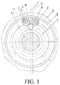
- FIG. 1 is a front view of an actively loaded rolling bearing of an eccentric shaft 11 and an inner ring 7 ;
- FIG. 2 is a front view of a rolling bearing actively loaded with a planet wheel spoke 3 and an outer ring 6 as active members;
- FIG. 3 is an axial sectional view of FIG. 1 ;
- FIG. 4 is an axial sectional view of FIG. 2 ;
- FIG. 5 shows a drive mode of an automobile single wheel—a sectional view of a left wheel loaded with a rolling bearing pair 14 (refer to FIG. 1 for details) and using an engaged pair hollow eccentric wheel coaxial shaft 26 of a planocentric set driven by a high-frequency high-speed alternating electromotor as an active body, and the right wheel is the same as the sectional view of the left wheel;
- FIG. 6 shows a double-drive mode of high-speed train pair wheels—loaded with a rolling bearing pair 14 (refer to FIG. 1 for details) and using an engaging pair hollow eccentric wheel coaxial shaft 26 of a planocentric set driven by a high-frequency high-speed alternating electromotor as an active body;
- FIG. 7 shows an eccentric wheel of a speed deceleration device of a general-type or helicopter propeller airplane loaded with a rolling bearing pair 14 (refer to FIG. 1 for details);
- FIG. 8 shows a planocentric set using a hollow eccentric wheel coaxial shaft 26 applied to a hollow main shaft of an adjustment bar 33 of a blade 31 mainly driven by a propeller of a ship or warship loaded with a rolling bearing pair 14 (refer to FIG. 1 for details);
- FIG. 9 is an axial sectional view of transferring a torque by an active member by using an outer ring 6 as a passive member loaded with a rolling bearing pair used by a spoke 3 of a planet engaged pair of a planocentric set to the outer ring 6 by using a spring 16 ;
- FIG. 10 is a sectional view of FIG. 9 along A-A;
- FIG. 11 is an axial sectional view of transferring a torque by an active member by using an inner ring 7 as a passive member and an eccentric shaft 11 as an active member loaded with a rolling bearing pair having a buffer spring of a planet engaged pair of a planocentric set to the inner gear by using the spring 16 ;
- FIG. 12 is a sectional view of FIG. 11 along A-A.
- 15 Rolling bearing pair loaded with a planet wheel spoke 3 as an active member (an eccentric wheel may be solid or hollow and refer to FIG. 2 for details); 16 : Stretch or compress a concurrent spring; 17 : Start key; 18 : Active key; 19 : Guard board; 20 : Screw; 21 : Inner gear ring; 22 : Planet wheel; 23 : Automobile wheel; 24 : Automobile wheel spoke; 25 : High-frequency high-speed alternating electromotor having a hollow rotor shaft; 26 : Hollow coaxial shaft of a hollow rotor shaft of a high-frequency high-speed prime power device and a hollow eccentric wheel of a planocentric set; 27 : Train wheel; 28 : Train pair wheel through shaft; 29 : Automobile pair wheel through shaft; 30 : Electromotor; 31 : Propeller; 32 : Hollow main shaft; and 33 : Blade spiral angle adjustment bar.
- the embodiment 1 is shown in FIG. 1 , FIG. 3 , FIG. 11 , and FIG. 12 .
- a main drive device of a planocentric set for three armed forces is provided.
- the main drive device of a planocentric set is installed at a bearing position of a planocentric set planet wheel and directly transfers power of a prime mover to the planet wheel to drive the planet wheel to implement differential rotation.
- the main drive device of a planocentric set mainly includes an inner ring 7 , an outer ring 6 , a rolling column 4 , and rolling pin shaft pairs 13 .
- the inner ring 7 is installed on an eccentric shaft 11 and rotates driven by the eccentric shaft 11 .
- the eccentric shaft 11 is driven by the prime mover.
- the rolling column 4 is installed between the inner ring 7 and the outer ring 6 and at a side closer to the inner ring 7 .
- the rolling pin shaft pair 13 is installed between the inner ring 7 and the outer ring 6 and at a side of the outer ring 6 .
- the rolling column 4 is in contact with one of the two neighboring rolling pin shaft pairs 13 to transmit the power to the rolling pin shaft pairs 13 in clockwise rotation and counter-clockwise rotation.
- the rolling pin shaft pair 13 drives the outer ring 6 to rotate, and the outer ring 6 drives a planet wheel spoke 3 to rotate, to drive the planocentric set planet wheel to perform translation and implement driving of the a planocentric set. As shown in FIG.
- the rolling pin shaft pair 13 includes a pin shaft 8 and a cycle of equispaced rolling pins 5 that are disposed in a cylinder 10 and in contact with the cylinder 10 , an inner edge of the rolling pin 5 is in contact with an outer edge of the pin shaft 8 , and two terminal shafts 9 of the pin shaft 8 are disposed in -shaped open pores at two ends of the outer ring 6 , as shown in FIG. 3 .
- the inner ring 7 is installed on the eccentric shaft 11 through interference fit, or may be connected to the eccentric shaft 11 in structures shown in FIG. 11 and FIG. 12 . As shown in FIG. 11 and FIG.
- the inner ring 7 is connected to the eccentric shaft 11 by using an active key 17 , a passive key 18 , and springs 16 , the active key 17 is fixed on the eccentric shaft 11 , the passive key 18 is fixed on the inner ring 7 , and two ends of each of the two springs 16 are respectively connected to two side surfaces of the active key 17 and two side surfaces of the passive key 18 , to implement buffer driving between the eccentric shaft 11 and the inner ring.
- the embodiment 2 is shown in FIG. 2 , FIG. 4 , FIG. 9 , and FIG. 10 .
- a main drive device of a planocentric set for three armed forces is provided.
- the main drive device mainly includes an inner ring 7 , an outer ring 6 , a rolling column 4 , and rolling pin shaft pairs 13 .
- the inner ring 7 is installed on an eccentric shaft 11 ;
- the rolling column 4 is installed between the inner ring 7 and the outer ring 6 and at a side closer to the outer ring 6 .
- the rolling pin shaft pair 13 is installed between the inner ring 7 and the outer ring 6 and at a side closer to the inner ring 7 .
- the outer ring 6 is connected to a spoke 3 of a planocentric set planet wheel, and drives the rolling column 4 to rotate.
- the rolling column 4 When the rolling column 4 is in contact with the outer ring 6 to transfer power, the rolling column 4 is in contact with one of the two rolling pin shaft pairs 13 to transmit the power to the rolling pin shaft pairs 13 in clockwise rotation and counter-clockwise rotation.
- the rolling pin shaft pair 13 drives the inner ring 7 to rotate, and the inner ring 7 drives the eccentric shaft 11 to rotate at a high speed, as shown in FIG. 2 .
- the rolling pin shaft pair 13 includes a pin shaft 8 and a cycle of equispaced rolling pins ( 5 ) that are disposed in a cylinder 10 and in contact with the cylinder 10 , as shown in FIG. 5 , an inner edge of the rolling pin 5 is in contact with an outer edge of the pin shaft 8 , and two terminal shafts 9 of the pin shaft 8 are disposed in -shaped open pores at two ends of the outer ring 6 .
- the outer ring 6 may be connected to the spoke 3 of the planocentric set planet wheel through interference fit. Alternatively, the outer ring may be connected to the spoke 3 of the planocentric set planet wheel in structures shown in FIG. 9 and FIG. 10 .
- the outer ring 6 is connected to the spoke 3 of the planocentric set planet wheel by using an active key 17 , a passive key 18 , and springs 16 .
- the active key 17 is fixed on the spoke 3 of the planocentric set planet wheel
- the passive key 18 is fixed on the outer ring 6
- two ends of each of the two springs 16 are respectively connected to two side surfaces of the active key 17 and two side surfaces of the passive key 18 , to implement buffer driving between the spoke 3 and the outer ring 6 .
- FIG. 5 shows a rolling bearing pair 14 (refer to FIG. 1 for details) loaded with an engaging pair hollow eccentric wheel coaxial shaft 26 of a planocentric set driven by a high-frequency high-speed alternating electromotor as an active body.
- FIG. 6 shows a specific structure of the present invention used in high-speed train pair wheel double-drive mode—a rolling bearing pair 14 (refer to FIG. 1 for details) loaded with a planocentric set engaged pair hollow eccentric wheel coaxial shaft 26 driven by a high-frequency high-speed alternating electromotor as an active body.
- FIG. 7 shows an application of the present invention in a speed deceleration device for driving a general-type or helicopter propeller airplane and shows a rolling bearing pair 14 (refer to FIG. 1 for details) loaded with an eccentric wheel.
- FIG. 8 shows an application of the present invention in a main drive device of a propeller of a ship or warship and shows a hollow eccentric wheel coaxial shaft 26 of a planocentric set applied to a hollow main shaft of an adjustment bar 33 of a blade 31 and loaded with a rolling bearing pair 14 (refer to FIG. 1 for details).
- the service life of the rolling column and the cylinder may be calculated according to a method of an international standard, and the rolling column and the cylinder can be massively produced as a serial product.
- the material of the inner and outer ring may be rolling bearing steel Gr 15.
- the rolling column and the rolling pin may use an international standard universal market product.
- the external diameter of the outer ring may be connected to a pore of the planet wheel spoke through interference fit, or may be connected by using a key.
- a spring buffer device By using a spring buffer device, the rolling column and the rolling pin can operate with each other dynamically.
- a dry oil groove may be additionally provided on two cooperation surfaces.
- the inner ring and a pore of the eccentric wheel cooperate with each other through interference fit or key linkage.
- pore cooperation between the inner ring and the eccentric wheel uses movable cooperation.
- thermal refining is performed on an inner gear ring of the dry oil groove additionally provided on a cooperation surface, and a carburized steel quenching and grinding process is performed on the planet wheel gear.
- the two springs are designed to be spring having both stretching and compression performance. Two ends of the spring are fixedly connected to the key.
- a sectional surface of a steel wire may be circular, square, ore a rectangular. High-carbon steel quenching or low-temperature tempering is performed on the material, and bluing treatment and chroming are performed on the appearance.
- a circumferential component force generated at a left and a right contact point between the rolling column 4 as an active member and the cylinder 10 as a passive member transfers a torque to the passive member.
- the active member rotates to the left, left contact points are in contact with each other, and right contact points are in an isolated state to reserve a gap.
- the active member rotates to the right, the right contact points are in contact with each other, and the left contact points are in an isolated state to reserve a gap.
- the inner ring 7 drives the rolling column 4 and transfers the torque to the outer ring 6 .
- the outer ring 6 and the planet wheel spoke 3 are connected through interference fit or key connection.
- the planet wheel spoke 3 and the planet wheel perform translation at a high speed, differential rotation is performed on the spoke and the conventional inner gear ring 21 , the inner gear ring 21 rotates at a low speed as an output member, thereby forming a speed deceleration device having buffer performance and loaded with the rolling bearing type planocentric set or the cycloidal pin wheel.
- an inner gear 21 of a conventional planocentric set or cycloidal pin wheel and the planet wheel spoke 3 that is engaged with the inner gear 21 and that performs translation and differential motion are used as active members, the outer ring 6 are driven by the keys 17 and 18 and the springs 16 , the outer ring 6 drives, by using the rolling column 4 , the cylinder 10 and the inner ring 7 to rotate.
- the inner ring 7 and the eccentric shaft are connected through interference fit or key connection, thereby forming a speed-accelerator having a buffer performance and loaded with a rolling bearing device type planocentric set or cycloidal pin wheel.
- the principle of the buffer device in the present invention is that the inner ring and the outer ring as the active member or the passive member are connected by using respective keys or two circumferential stretching or compression springs, to adapt to working condition requirements in clockwise and counter-clockwise rotation.
- a torque is transferred by using the spring.
- the buffer performance of the spring conforms to the law of conservation of energy. For example, a compression stroke of the spring is 50 mm, and a resilient shape change of a pure positive drive shaft system is ⁇ 1 mm, and therefore, a compelling force is reduced by 50 times is rotation. This is quite importance to an automobile, a train and an armored vehicle. According to the present invention, the service life of the vehicle can be prolonged.
- Parts not related to the present invention are the same as the prior art or may be implemented by using the prior art.
Landscapes
- Engineering & Computer Science (AREA)
- Mechanical Engineering (AREA)
- Power Engineering (AREA)
- General Engineering & Computer Science (AREA)
- Aviation & Aerospace Engineering (AREA)
- Chemical & Material Sciences (AREA)
- Combustion & Propulsion (AREA)
- Transportation (AREA)
- Retarders (AREA)
Abstract
Description
Claims (10)
Applications Claiming Priority (3)
| Application Number | Priority Date | Filing Date | Title |
|---|---|---|---|
| CN201710840441.6A CN107588158B (en) | 2017-09-18 | 2017-09-18 | Small tooth difference main drive |
| CN201710840441 | 2017-09-18 | ||
| CN201710840441.6 | 2017-09-18 |
Publications (2)
| Publication Number | Publication Date |
|---|---|
| US20190085942A1 US20190085942A1 (en) | 2019-03-21 |
| US10724605B2 true US10724605B2 (en) | 2020-07-28 |
Family
ID=61048390
Family Applications (1)
| Application Number | Title | Priority Date | Filing Date |
|---|---|---|---|
| US16/100,998 Expired - Fee Related US10724605B2 (en) | 2017-09-18 | 2018-08-10 | Main drive device of planocentric set |
Country Status (3)
| Country | Link |
|---|---|
| US (1) | US10724605B2 (en) |
| CN (1) | CN107588158B (en) |
| DE (1) | DE102018122815A1 (en) |
Families Citing this family (2)
| Publication number | Priority date | Publication date | Assignee | Title |
|---|---|---|---|---|
| CN111162655B (en) * | 2019-12-27 | 2025-03-07 | 苏州泰格驱动技术有限公司 | A magnetic deceleration device |
| JP7493340B2 (en) * | 2020-01-17 | 2024-05-31 | 三菱重工業株式会社 | Electric vehicles |
Citations (4)
| Publication number | Priority date | Publication date | Assignee | Title |
|---|---|---|---|---|
| US20060147142A1 (en) * | 2004-05-04 | 2006-07-06 | Natan Bezyaiko | Method for multi orbital engagement of surfaces by free rolling bodies and multi orbital devices based on this method |
| US20130059693A1 (en) * | 2011-09-05 | 2013-03-07 | Zupeng Fang | High Efficient and High Power Plane Centric Gear Unit |
| US20170314644A1 (en) * | 2016-02-04 | 2017-11-02 | Nidec Shimpo Corporation | Speed reducer |
| US20180031079A1 (en) * | 2016-07-28 | 2018-02-01 | Nabtesco Corporation | Gear device |
Family Cites Families (3)
| Publication number | Priority date | Publication date | Assignee | Title |
|---|---|---|---|---|
| CN1093443A (en) * | 1993-04-06 | 1994-10-12 | 张富生 | Sealed type rackless roller bearing |
| JP2015175496A (en) * | 2014-03-18 | 2015-10-05 | セイコーエプソン株式会社 | Bearing, speed reducer, robot hand, and robot |
| CN206000853U (en) * | 2016-08-24 | 2017-03-08 | 山东利腾轴承制造有限公司 | A kind of large-scale ball bearing |
-
2017
- 2017-09-18 CN CN201710840441.6A patent/CN107588158B/en not_active Expired - Fee Related
-
2018
- 2018-08-10 US US16/100,998 patent/US10724605B2/en not_active Expired - Fee Related
- 2018-09-18 DE DE102018122815.5A patent/DE102018122815A1/en not_active Withdrawn
Patent Citations (5)
| Publication number | Priority date | Publication date | Assignee | Title |
|---|---|---|---|---|
| US20060147142A1 (en) * | 2004-05-04 | 2006-07-06 | Natan Bezyaiko | Method for multi orbital engagement of surfaces by free rolling bodies and multi orbital devices based on this method |
| US20130059693A1 (en) * | 2011-09-05 | 2013-03-07 | Zupeng Fang | High Efficient and High Power Plane Centric Gear Unit |
| US9022896B2 (en) * | 2011-09-05 | 2015-05-05 | Zupeng Fang | High efficient and high power plane centric gear unit |
| US20170314644A1 (en) * | 2016-02-04 | 2017-11-02 | Nidec Shimpo Corporation | Speed reducer |
| US20180031079A1 (en) * | 2016-07-28 | 2018-02-01 | Nabtesco Corporation | Gear device |
Non-Patent Citations (1)
| Title |
|---|
| M.B. Peterson, et al; "Wear Control Handbook"; American Society of Mechanical Engineers; 1980; 3 pgs total. |
Also Published As
| Publication number | Publication date |
|---|---|
| CN107588158B (en) | 2021-02-26 |
| US20190085942A1 (en) | 2019-03-21 |
| CN107588158A (en) | 2018-01-16 |
| DE102018122815A1 (en) | 2019-03-21 |
Similar Documents
| Publication | Publication Date | Title |
|---|---|---|
| JP5764702B2 (en) | Coaxial crankless engine | |
| CN204828503U (en) | Double pendulum line RV reduction gear for robot | |
| US10865852B2 (en) | Powertrain with cycloidal mechanism having reinforced contact surfaces | |
| US10724605B2 (en) | Main drive device of planocentric set | |
| CN202203345U (en) | Compound precision cycloid decelerator | |
| CN110154752A (en) | Vehicle propulsion system | |
| EP2630362A1 (en) | Internal combustion engine including crankshaft that is rotated while engine is in a non-fueled mode and method of operating an engine | |
| CN110762174B (en) | Cam-pressurized conical disc type continuously variable transmission | |
| CN105848949B (en) | Traction system for a vehicle | |
| KR101974530B1 (en) | Two-speed transmission for electric vehicle | |
| US10233906B2 (en) | Joint member for wind power generation apparatus, and wind power generation apparatus | |
| CN102242795B (en) | Precision cycloid decelerator | |
| CN102563003A (en) | Power distributor and unitary power distribution system of hybrid power automobile | |
| US20210107347A1 (en) | Driving device | |
| CN110304229B (en) | A marine steering gear with two-stage mechanical transmission structure | |
| CN203146711U (en) | Mechanical torque transmission joint with harmonic speed reducer and cross auxiliary bearing combined | |
| CN202203344U (en) | Precision cycloidal speed reducer | |
| US9022896B2 (en) | High efficient and high power plane centric gear unit | |
| CN110953308B (en) | Gear ring eccentric rotation stepless speed change method | |
| CN106151390B (en) | Speed reducer | |
| CN108458089A (en) | A kind of belt pulley of automobile engine | |
| CN118959555A (en) | Electromechanical parallel compound nutating reducer | |
| KR20120055340A (en) | Transmission for electric vehicle | |
| CN209762147U (en) | compact gear transmission mechanism | |
| CN110529563A (en) | A kind of four-speed gear shift system of four jackshaft of dual power source |
Legal Events
| Date | Code | Title | Description |
|---|---|---|---|
| FEPP | Fee payment procedure |
Free format text: ENTITY STATUS SET TO UNDISCOUNTED (ORIGINAL EVENT CODE: BIG.); ENTITY STATUS OF PATENT OWNER: SMALL ENTITY |
|
| FEPP | Fee payment procedure |
Free format text: ENTITY STATUS SET TO SMALL (ORIGINAL EVENT CODE: SMAL); ENTITY STATUS OF PATENT OWNER: SMALL ENTITY |
|
| STPP | Information on status: patent application and granting procedure in general |
Free format text: APPLICATION DISPATCHED FROM PREEXAM, NOT YET DOCKETED |
|
| STPP | Information on status: patent application and granting procedure in general |
Free format text: DOCKETED NEW CASE - READY FOR EXAMINATION |
|
| STPP | Information on status: patent application and granting procedure in general |
Free format text: NON FINAL ACTION MAILED |
|
| STPP | Information on status: patent application and granting procedure in general |
Free format text: NOTICE OF ALLOWANCE MAILED -- APPLICATION RECEIVED IN OFFICE OF PUBLICATIONS |
|
| STPP | Information on status: patent application and granting procedure in general |
Free format text: PUBLICATIONS -- ISSUE FEE PAYMENT VERIFIED |
|
| STCF | Information on status: patent grant |
Free format text: PATENTED CASE |
|
| FEPP | Fee payment procedure |
Free format text: MAINTENANCE FEE REMINDER MAILED (ORIGINAL EVENT CODE: REM.); ENTITY STATUS OF PATENT OWNER: SMALL ENTITY |
|
| LAPS | Lapse for failure to pay maintenance fees |
Free format text: PATENT EXPIRED FOR FAILURE TO PAY MAINTENANCE FEES (ORIGINAL EVENT CODE: EXP.); ENTITY STATUS OF PATENT OWNER: SMALL ENTITY |
|
| STCH | Information on status: patent discontinuation |
Free format text: PATENT EXPIRED DUE TO NONPAYMENT OF MAINTENANCE FEES UNDER 37 CFR 1.362 |
|
| FP | Lapsed due to failure to pay maintenance fee |
Effective date: 20240728 |