US10711955B2 - Rubberized light housing and adaptor - Google Patents

Rubberized light housing and adaptor Download PDF

Info

Publication number
US10711955B2
US10711955B2 US16/221,196 US201816221196A US10711955B2 US 10711955 B2 US10711955 B2 US 10711955B2 US 201816221196 A US201816221196 A US 201816221196A US 10711955 B2 US10711955 B2 US 10711955B2
Authority
US
United States
Prior art keywords
elongated body
ribs
housing
light housing
interior
Prior art date
Legal status (The legal status is an assumption and is not a legal conclusion. Google has not performed a legal analysis and makes no representation as to the accuracy of the status listed.)
Active
Application number
US16/221,196
Other versions
US20190186701A1 (en
Inventor
Nate Mullen
Current Assignee (The listed assignees may be inaccurate. Google has not performed a legal analysis and makes no representation or warranty as to the accuracy of the list.)
Individual
Original Assignee
Individual
Priority date (The priority date is an assumption and is not a legal conclusion. Google has not performed a legal analysis and makes no representation as to the accuracy of the date listed.)
Filing date
Publication date
Application filed by Individual filed Critical Individual
Priority to US16/221,196 priority Critical patent/US10711955B2/en
Publication of US20190186701A1 publication Critical patent/US20190186701A1/en
Application granted granted Critical
Publication of US10711955B2 publication Critical patent/US10711955B2/en
Active legal-status Critical Current
Anticipated expiration legal-status Critical

Links

Images

Classifications

    • FMECHANICAL ENGINEERING; LIGHTING; HEATING; WEAPONS; BLASTING
    • F21LIGHTING
    • F21SNON-PORTABLE LIGHTING DEVICES; SYSTEMS THEREOF; VEHICLE LIGHTING DEVICES SPECIALLY ADAPTED FOR VEHICLE EXTERIORS
    • F21S4/00Lighting devices or systems using a string or strip of light sources
    • F21S4/20Lighting devices or systems using a string or strip of light sources with light sources held by or within elongate supports
    • FMECHANICAL ENGINEERING; LIGHTING; HEATING; WEAPONS; BLASTING
    • F21LIGHTING
    • F21VFUNCTIONAL FEATURES OR DETAILS OF LIGHTING DEVICES OR SYSTEMS THEREOF; STRUCTURAL COMBINATIONS OF LIGHTING DEVICES WITH OTHER ARTICLES, NOT OTHERWISE PROVIDED FOR
    • F21V31/00Gas-tight or water-tight arrangements
    • F21V31/005Sealing arrangements therefor
    • FMECHANICAL ENGINEERING; LIGHTING; HEATING; WEAPONS; BLASTING
    • F21LIGHTING
    • F21VFUNCTIONAL FEATURES OR DETAILS OF LIGHTING DEVICES OR SYSTEMS THEREOF; STRUCTURAL COMBINATIONS OF LIGHTING DEVICES WITH OTHER ARTICLES, NOT OTHERWISE PROVIDED FOR
    • F21V15/00Protecting lighting devices from damage
    • F21V15/01Housings, e.g. material or assembling of housing parts
    • F21V15/012Housings with variable shape or dimensions, e.g. by means of elastically deformable materials or by movement of parts forming telescopic extensions of the housing body
    • FMECHANICAL ENGINEERING; LIGHTING; HEATING; WEAPONS; BLASTING
    • F21LIGHTING
    • F21VFUNCTIONAL FEATURES OR DETAILS OF LIGHTING DEVICES OR SYSTEMS THEREOF; STRUCTURAL COMBINATIONS OF LIGHTING DEVICES WITH OTHER ARTICLES, NOT OTHERWISE PROVIDED FOR
    • F21V21/00Supporting, suspending, or attaching arrangements for lighting devices; Hand grips
    • F21V21/02Wall, ceiling, or floor bases; Fixing pendants or arms to the bases
    • F21V21/04Recessed bases
    • FMECHANICAL ENGINEERING; LIGHTING; HEATING; WEAPONS; BLASTING
    • F21LIGHTING
    • F21VFUNCTIONAL FEATURES OR DETAILS OF LIGHTING DEVICES OR SYSTEMS THEREOF; STRUCTURAL COMBINATIONS OF LIGHTING DEVICES WITH OTHER ARTICLES, NOT OTHERWISE PROVIDED FOR
    • F21V5/00Refractors for light sources
    • F21V5/04Refractors for light sources of lens shape
    • FMECHANICAL ENGINEERING; LIGHTING; HEATING; WEAPONS; BLASTING
    • F21LIGHTING
    • F21SNON-PORTABLE LIGHTING DEVICES; SYSTEMS THEREOF; VEHICLE LIGHTING DEVICES SPECIALLY ADAPTED FOR VEHICLE EXTERIORS
    • F21S8/00Lighting devices intended for fixed installation
    • F21S8/02Lighting devices intended for fixed installation of recess-mounted type, e.g. downlighters
    • F21S8/026Lighting devices intended for fixed installation of recess-mounted type, e.g. downlighters intended to be recessed in a ceiling or like overhead structure, e.g. suspended ceiling
    • FMECHANICAL ENGINEERING; LIGHTING; HEATING; WEAPONS; BLASTING
    • F21LIGHTING
    • F21VFUNCTIONAL FEATURES OR DETAILS OF LIGHTING DEVICES OR SYSTEMS THEREOF; STRUCTURAL COMBINATIONS OF LIGHTING DEVICES WITH OTHER ARTICLES, NOT OTHERWISE PROVIDED FOR
    • F21V11/00Screens not covered by groups F21V1/00, F21V3/00, F21V7/00 or F21V9/00
    • F21V11/02Screens not covered by groups F21V1/00, F21V3/00, F21V7/00 or F21V9/00 using parallel laminae or strips, e.g. of Venetian-blind type
    • FMECHANICAL ENGINEERING; LIGHTING; HEATING; WEAPONS; BLASTING
    • F21LIGHTING
    • F21VFUNCTIONAL FEATURES OR DETAILS OF LIGHTING DEVICES OR SYSTEMS THEREOF; STRUCTURAL COMBINATIONS OF LIGHTING DEVICES WITH OTHER ARTICLES, NOT OTHERWISE PROVIDED FOR
    • F21V11/00Screens not covered by groups F21V1/00, F21V3/00, F21V7/00 or F21V9/00
    • F21V11/06Screens not covered by groups F21V1/00, F21V3/00, F21V7/00 or F21V9/00 using crossed laminae or strips, e.g. grid-shaped louvers; using lattices or honeycombs

Definitions

  • the present invention is directed to a light housing and adaptor for using light bulbs with well lights and similar fixtures having circular cans. More particularly, the rubberized light housing is for use with MR-16 or similar parabolic light bulbs of various sizes.
  • Prior art devices for mounting light bulbs in well lights or similar structures tend to expose the light bulb and electrical connections to environmental factors.
  • the light bulbs are often much smaller than the cans or other housing structures found in such fixtures.
  • Such bulbs are often retained using rigid metal structures that a forced into place or permanently attached to the housing.
  • Such prior art devices are difficult to work with, repair, and/or replace.
  • the present invention is directed to a light housing, in particular, a rubberized light housing having an elongated body with a generally tubular shape.
  • the elongated body has an open first end and closed second end, where the first end is configured to receive and retain a light bulb proximate thereto.
  • a sealing port is included in the second end. The sealing port is configured to hermetically seal against electrical wires passed into an interior of the elongated body.
  • a plurality of ribs is uniformly spaced around a perimeter of the first end of the elongated body.
  • the first end may sealingly receive and retain the light bulb so as to hermetically seal the interior of the elongated body.
  • a lens may be sealingly disposed in a lens channel proximate the open first end of the elongated body. The lens may hermetically seal the interior of the elongated body.
  • a support rib may be disposed on the second end of the elongated body, the support rib configured for receiving a hook or other mounting means to retain the light housing.
  • Each of the plurality of ribs is resiliently flexible and configured for friction contact with an interior of a lighting can. At least one of the plurality of ribs is capable of being cut so as to reduce a span of the plurality of ribs.
  • the elongated body, sealing port, and plurality of ribs are preferably all manufactured from a rubber material.
  • the light housing may also include an adaptor ring having a plurality of larger ribs uniformly spaced around a perimeter thereof.
  • the adaptor ring is configured for concentric engagement with the plurality of ribs on the first end of the elongated body.
  • the adaptor ring is configured to enlarge a span of the plurality of ribs.
  • the adaptor ring is also resiliently flexible and configured for friction contact with an interior of a larger lighting can.
  • FIG. 1 is a perspective view of a can light and shroud incorporating the inventive rubberized light housing
  • FIG. 2 is perspective view of the can light and shroud from the reverse angle of FIG. 1 ;
  • FIG. 3 is a perspective view of the inventive rubberized light housing
  • FIG. 4 is a perspective view of the inventive rubberized light housing from the reverse angle of FIG. 3 ;
  • FIG. 5 is a perspective view of the inventive can light adaptor for use with the rubberized light housing
  • FIG. 6 is a perspective view of a common can light housing
  • FIG. 7 is a perspective view of a common can light housing from the reverse angle of FIG. 6 ;
  • FIG. 8 is a perspective view of a common cap for a can light housing
  • FIG. 9 is a perspective view of a common shroud and honeycomb louver for a can light housing
  • FIG. 10 is a perspective view of a honeycomb louver for a can light
  • FIG. 11 is a perspective view of a common angle shroud for a can light housing
  • FIG. 12 is a perspective view of a common grated shroud for a can light housing.
  • FIG. 13 is a perspective view of common eyelid shroud for a can light housing.
  • the present invention is directed to a rubberized light housing and adaptor for use with can lights and similar fixtures.
  • the rubberized light housing will be generally referred to by reference numeral 20 and the adaptor by reference numeral 40 .
  • FIGS. 3-5 generally show the rubberized light housing 20 from multiple angles and the adaptor 40 .
  • the rubberized light housing 20 has a generally tubular elongated body 22 having an open top end 24 and a closed bottom end 26 .
  • the elongated body 22 and open top end 24 are generally sized to accommodate and closely match an MR-16 or similarly sized light bulb 28 ( FIG. 1 ) having a generally parabolic reflector body.
  • the size of the body on the bulb 28 is preferably configured to closely match the interior diameter or circumference of the body 22 or open end 24 .
  • the rubberized construction of the housing 20 allows for flexibility and durability of the housing when installed in desired locations.
  • annular edge of the bulb 28 may fit in a channel 24 a around the interior of the open end 24 of the housing 20 . If the bulb 28 is not so enclosed, then an annular edge of the bulb 28 may fit into a second channel (not shown) around the interior of the open end 24 and the invention may include a separate lens (not shown) that fits into the channel 24 a .
  • the purpose of the annular edge of the bulb 28 or separate lens fitting to the channel 24 a is to provide a substantially water-tight seal to the open end 24 when the bulb 28 is installed. With the water-tight seal, a bulb installed in the housing 20 will be protected against intrusion by water or other moisture.
  • the bulb 28 may be any known type of illumination device, incandescent, low-voltage, halogen, LED, or similarly known or to be discovered illumination device. Alternatively, the bulb 28 may be replaced with any similar electrical apparatus that one may need to secure in a water-tight housing as described below.
  • the ribs 30 are designed to extend radially away from the body 22 so as to make contact with a surrounding can 32 ( FIGS. 1 and 2 ) or similar light fixture enclosure.
  • the ribs 30 may be provided in various quantities and arrangements intended to exert sufficient force against an interior wall 34 of the can 32 so as to reliably maintain positioning within the can 32 .
  • the ribs 30 are preferably resiliently flexible so as to compress sufficiently to allow the housing 20 to fit within an interior of the can 32 with various amount of deflection and return force. Since the ribs 32 are rubberized like the rest of the housing 20 , the ribs 30 may be cut or trimmed as needed to allow the housing 20 to fit into a smaller sized can 32 .
  • the ribs 30 may be provided in odd (3, 5, etc.) or even (2, 4, 6, etc.) quantities, being uniformly spaced around the perimeter of the housing 20 .
  • the ribs are preferably arranged in opposed pairs 30 a , 30 b so as to provide an opposed exertion of force across the opposed pairs 30 a , 30 b .
  • Such opposed exertion of force provides a more reliably secure positioning of the housing 20 in the can 32 .
  • the housing 20 includes at least three ribs 30 to provide a uniform exertion of force against the interior wall 34 at least every one-hundred-twenty degrees around the perimeter of the housing 20 .
  • the housing includes at least four ribs 30 , to provide an exertion of force against the interior wall 34 at least every ninety degrees with the force being an opposed exertion of force every one-hundred-eighty degrees around the perimeter of the housing 20 .
  • the housing 20 includes six ribs 30 to provide an exertion of force against the interior wall 34 at least every sixty degrees, with the force being an opposed exertion of force every one-hundred-twenty degrees around the perimeter of the housing 20 .
  • the closed bottom 26 of the housing 20 is preferably completely sealed so as to be water-tight.
  • the closed bottom 26 may include a self-sealing port 36 that includes an interior diaphragm (not shown) or similar structure that seals against the passage of water but may selectively allow the passage of wires (not shown) or a similar electrical transmission apparatus.
  • the diaphragm is preferably resiliently configured so as to provide a water-tight seal around any wire or apparatus that is passed through the port 36 .
  • the wire or other apparatus passed through the port 36 is designed to transmit electrical current to a bulb 28 or other electrical device contained within the housing 20 .
  • the bottom end 26 of the housing 20 may also include an exterior support 38 or similar structure that includes a hole 38 a configured to provide a place to attach the housing 20 to a hook, nail or other environmental support (not shown).
  • the exterior support 38 and hole 38 a are used when the housing 20 is not mounted in a can 32 or can be used as additional support for holding the housing 20 in a fixed position within the can 32 .
  • the inventive apparatus may also include an adaptor 40 that is generally circular in configuration and has a central opening 42 configured to receive the body 22 of the housing 20 .
  • the central opening 42 preferably has a number of slots 44 corresponding to the number of ribs 30 on the housing 20 .
  • the ribs 30 of the housing 20 are configured to fit in a tight manner within the slots 44 such that the adaptor 40 is effectively an extension of the housing 20 .
  • the slots 44 preferably have an end 44 a that is substantially blocked or closed so that the ribs 30 do not pass all of the way through.
  • the ribs 30 preferably rest against the blocked ends 44 a of the slots 44 so as to engage the adaptor 40 rather than pass completely through.
  • the exterior perimeter of the adaptor 40 includes a number of larger ribs 46 spaced and configured using similar considerations as discussed above in connection with the ribs 30 .
  • the larger ribs 46 are equal in number and configuration as the ribs 30 of the housing 20 .
  • the adaptor 40 and larger ribs 46 are preferably rubberized and flexibly resilient. Given their larger diameter, the adaptor 40 and larger ribs 46 are preferably less flexible than the housing 20 and ribs 30 to minimize an undesired collapse of the same.
  • the adaptor 40 is intended to allow the rubberized light housing 20 to be used with larger cans 48 ( FIGS. 6 and 7 ) having a diameter that is too large for just the ribs 30 of the housing 20 .
  • the larger ribs 46 on the adaptor 40 provide a wider reach to an interior wall 48 a in a larger can 48 .
  • a person may be able to use a can 32 that is appropriately sized for the ribs 30 of the housing 20 .
  • the larger can 48 may be already installed and it is much simpler to use the adaptor 40 having the larger ribs 46 with the housing 20 rather than to remove and replace the larger can 48 with a smaller can 32 .
  • FIGS. 8-13 illustrate various forms of shrouds and louvers for use with the cans 32 , 48 that accommodate the housing 20 and/or adaptor 40 .
  • a common cap 50 for a can light 32 , 48 is shown.
  • the common cap 50 generally matches the shape of the can light 32 , 48 in that it is configured to fit around the can 32 , 48 as a sleeve.
  • the cap 50 may have a lens (not shown in FIG. 8 ) or other insert. As illustrated, the cap 50 may also have a slight tilt or angle to provide some directional illumination.
  • a cap 50 is shown including a honeycomb louver 52 .
  • FIG. 10 illustrates the honeycomb louver 52 separate from the cap 50 .
  • FIG. 11 illustrates an angle shroud 54 that has an angled wall 54 a to direct illumination from light source and has a base 54 b that is designed to fit inside of the can 32 , 48 to retain the angle shroud 54 on the fixture.
  • An annular ring 54 c surrounds the angle shroud 54 to overhand the edge of the can 32 , 48 .
  • FIG. 12 illustrates a grated shroud 56 having a plurality of grates 56 a , a base 56 b , and an annular ring 56 c , as described with the angle shroud 54 .
  • FIG. 13 illustrates and eyelid shroud 58 having a crescent opening 58 a , a base 58 b , and an annular ring 58 c .
  • Such caps, louvers and shrouds are designed to diffuse or direct the light source as desired.

Landscapes

  • Engineering & Computer Science (AREA)
  • General Engineering & Computer Science (AREA)
  • Arrangement Of Elements, Cooling, Sealing, Or The Like Of Lighting Devices (AREA)

Abstract

A resiliently flexible, rubberized light housing for sealingly enclosing and protecting a light bulb or fixture against moisture and other intrusion. The housing has an elongated, generally tubular body with an open first end and a closed second end. The open first end may receive and retain a bulb or fixture that has an exposed bulb or element or is environmentally sealed. If the bulb or fixture is sealed, then the same may hermetically seal the open first end. If the bulb or fixture is not sealed, then a lens may be included to hermetically seal the open first end with the bulb or fixture in the interior. Electrical wires for connection to the bulb or fixture may be passed through a sealing port on the closed send end. The plurality of ribs are configured for friction contact with the inside of a lighting can.

Description

RELATED APPLICATION
This application claims the benefit of U.S. Provisional Application No. 62/607,235, filed on Dec. 18, 2017.
BACKGROUND OF THE INVENTION
The present invention is directed to a light housing and adaptor for using light bulbs with well lights and similar fixtures having circular cans. More particularly, the rubberized light housing is for use with MR-16 or similar parabolic light bulbs of various sizes.
Prior art devices for mounting light bulbs in well lights or similar structures tend to expose the light bulb and electrical connections to environmental factors. In addition, the light bulbs are often much smaller than the cans or other housing structures found in such fixtures. Such bulbs are often retained using rigid metal structures that a forced into place or permanently attached to the housing. Such prior art devices are difficult to work with, repair, and/or replace.
Accordingly, there is a need for a light housing that makes it easier to install light bulbs in well lights and similar structures, as well as, provides protection from environmental hazards like water or moisture. The present invention fulfills these needs and provides other related advantages.
SUMMARY OF THE INVENTION
The present invention is directed to a light housing, in particular, a rubberized light housing having an elongated body with a generally tubular shape. The elongated body has an open first end and closed second end, where the first end is configured to receive and retain a light bulb proximate thereto. A sealing port is included in the second end. The sealing port is configured to hermetically seal against electrical wires passed into an interior of the elongated body. A plurality of ribs is uniformly spaced around a perimeter of the first end of the elongated body.
The first end may sealingly receive and retain the light bulb so as to hermetically seal the interior of the elongated body. Alternatively, a lens may be sealingly disposed in a lens channel proximate the open first end of the elongated body. The lens may hermetically seal the interior of the elongated body. A support rib may be disposed on the second end of the elongated body, the support rib configured for receiving a hook or other mounting means to retain the light housing.
Each of the plurality of ribs is resiliently flexible and configured for friction contact with an interior of a lighting can. At least one of the plurality of ribs is capable of being cut so as to reduce a span of the plurality of ribs. The elongated body, sealing port, and plurality of ribs are preferably all manufactured from a rubber material.
The light housing may also include an adaptor ring having a plurality of larger ribs uniformly spaced around a perimeter thereof. The adaptor ring is configured for concentric engagement with the plurality of ribs on the first end of the elongated body. The adaptor ring is configured to enlarge a span of the plurality of ribs. The adaptor ring is also resiliently flexible and configured for friction contact with an interior of a larger lighting can.
Other features and advantages of the present invention will become apparent from the following more detailed description, taken in conjunction with the accompanying drawings, which illustrate, by way of example, the principles of the invention.
BRIEF DESCRIPTION OF THE DRAWINGS
The accompanying drawings illustrate the invention. In such drawings:
FIG. 1 is a perspective view of a can light and shroud incorporating the inventive rubberized light housing;
FIG. 2 is perspective view of the can light and shroud from the reverse angle of FIG. 1;
FIG. 3 is a perspective view of the inventive rubberized light housing;
FIG. 4, is a perspective view of the inventive rubberized light housing from the reverse angle of FIG. 3;
FIG. 5 is a perspective view of the inventive can light adaptor for use with the rubberized light housing;
FIG. 6 is a perspective view of a common can light housing;
FIG. 7 is a perspective view of a common can light housing from the reverse angle of FIG. 6;
FIG. 8 is a perspective view of a common cap for a can light housing;
FIG. 9 is a perspective view of a common shroud and honeycomb louver for a can light housing;
FIG. 10 is a perspective view of a honeycomb louver for a can light;
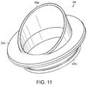
FIG. 11 is a perspective view of a common angle shroud for a can light housing;
FIG. 12 is a perspective view of a common grated shroud for a can light housing; and
FIG. 13 is a perspective view of common eyelid shroud for a can light housing.
DETAILED DESCRIPTION OF THE PREFERRED EMBODIMENTS
The present invention is directed to a rubberized light housing and adaptor for use with can lights and similar fixtures. In the following detailed description, the rubberized light housing will be generally referred to by reference numeral 20 and the adaptor by reference numeral 40. FIGS. 3-5 generally show the rubberized light housing 20 from multiple angles and the adaptor 40.
With particular reference to FIGS. 3 and 4, the rubberized light housing 20 has a generally tubular elongated body 22 having an open top end 24 and a closed bottom end 26. The elongated body 22 and open top end 24 are generally sized to accommodate and closely match an MR-16 or similarly sized light bulb 28 (FIG. 1) having a generally parabolic reflector body. The size of the body on the bulb 28 is preferably configured to closely match the interior diameter or circumference of the body 22 or open end 24. The rubberized construction of the housing 20 allows for flexibility and durability of the housing when installed in desired locations.
When the bulb 28 is enclosed with an integral lens or similar cover, an annular edge of the bulb 28 may fit in a channel 24 a around the interior of the open end 24 of the housing 20. If the bulb 28 is not so enclosed, then an annular edge of the bulb 28 may fit into a second channel (not shown) around the interior of the open end 24 and the invention may include a separate lens (not shown) that fits into the channel 24 a. The purpose of the annular edge of the bulb 28 or separate lens fitting to the channel 24 a is to provide a substantially water-tight seal to the open end 24 when the bulb 28 is installed. With the water-tight seal, a bulb installed in the housing 20 will be protected against intrusion by water or other moisture.
The bulb 28 may be any known type of illumination device, incandescent, low-voltage, halogen, LED, or similarly known or to be discovered illumination device. Alternatively, the bulb 28 may be replaced with any similar electrical apparatus that one may need to secure in a water-tight housing as described below.
An exterior surface of the open end 24 of the housing 20 is surrounded by a plurality of uniformly spaced ribs 30. The ribs 30 are designed to extend radially away from the body 22 so as to make contact with a surrounding can 32 (FIGS. 1 and 2) or similar light fixture enclosure. The ribs 30 may be provided in various quantities and arrangements intended to exert sufficient force against an interior wall 34 of the can 32 so as to reliably maintain positioning within the can 32. The ribs 30 are preferably resiliently flexible so as to compress sufficiently to allow the housing 20 to fit within an interior of the can 32 with various amount of deflection and return force. Since the ribs 32 are rubberized like the rest of the housing 20, the ribs 30 may be cut or trimmed as needed to allow the housing 20 to fit into a smaller sized can 32.
The ribs 30 may be provided in odd (3, 5, etc.) or even (2, 4, 6, etc.) quantities, being uniformly spaced around the perimeter of the housing 20. In the case of an even number of ribs 30, the ribs are preferably arranged in opposed pairs 30 a, 30 b so as to provide an opposed exertion of force across the opposed pairs 30 a, 30 b. Such opposed exertion of force provides a more reliably secure positioning of the housing 20 in the can 32. Preferably, the housing 20 includes at least three ribs 30 to provide a uniform exertion of force against the interior wall 34 at least every one-hundred-twenty degrees around the perimeter of the housing 20. Most preferably, the housing includes at least four ribs 30, to provide an exertion of force against the interior wall 34 at least every ninety degrees with the force being an opposed exertion of force every one-hundred-eighty degrees around the perimeter of the housing 20. Ideally, the housing 20 includes six ribs 30 to provide an exertion of force against the interior wall 34 at least every sixty degrees, with the force being an opposed exertion of force every one-hundred-twenty degrees around the perimeter of the housing 20.
The closed bottom 26 of the housing 20 is preferably completely sealed so as to be water-tight. The closed bottom 26 may include a self-sealing port 36 that includes an interior diaphragm (not shown) or similar structure that seals against the passage of water but may selectively allow the passage of wires (not shown) or a similar electrical transmission apparatus. The diaphragm is preferably resiliently configured so as to provide a water-tight seal around any wire or apparatus that is passed through the port 36. The wire or other apparatus passed through the port 36 is designed to transmit electrical current to a bulb 28 or other electrical device contained within the housing 20.
The bottom end 26 of the housing 20 may also include an exterior support 38 or similar structure that includes a hole 38 a configured to provide a place to attach the housing 20 to a hook, nail or other environmental support (not shown). The exterior support 38 and hole 38 a are used when the housing 20 is not mounted in a can 32 or can be used as additional support for holding the housing 20 in a fixed position within the can 32.
The inventive apparatus may also include an adaptor 40 that is generally circular in configuration and has a central opening 42 configured to receive the body 22 of the housing 20. The central opening 42 preferably has a number of slots 44 corresponding to the number of ribs 30 on the housing 20. The ribs 30 of the housing 20 are configured to fit in a tight manner within the slots 44 such that the adaptor 40 is effectively an extension of the housing 20. The slots 44 preferably have an end 44 a that is substantially blocked or closed so that the ribs 30 do not pass all of the way through. The ribs 30 preferably rest against the blocked ends 44 a of the slots 44 so as to engage the adaptor 40 rather than pass completely through.
The exterior perimeter of the adaptor 40 includes a number of larger ribs 46 spaced and configured using similar considerations as discussed above in connection with the ribs 30. Ideally, the larger ribs 46 are equal in number and configuration as the ribs 30 of the housing 20. As with the housing 20 and ribs 30, the adaptor 40 and larger ribs 46 are preferably rubberized and flexibly resilient. Given their larger diameter, the adaptor 40 and larger ribs 46 are preferably less flexible than the housing 20 and ribs 30 to minimize an undesired collapse of the same.
The adaptor 40 is intended to allow the rubberized light housing 20 to be used with larger cans 48 (FIGS. 6 and 7) having a diameter that is too large for just the ribs 30 of the housing 20. The larger ribs 46 on the adaptor 40 provide a wider reach to an interior wall 48 a in a larger can 48. On original installations, a person may be able to use a can 32 that is appropriately sized for the ribs 30 of the housing 20. However, in retrofit installations, the larger can 48 may be already installed and it is much simpler to use the adaptor 40 having the larger ribs 46 with the housing 20 rather than to remove and replace the larger can 48 with a smaller can 32.
FIGS. 8-13 illustrate various forms of shrouds and louvers for use with the cans 32, 48 that accommodate the housing 20 and/or adaptor 40. In FIG. 8, a common cap 50 for a can light 32, 48 is shown. The common cap 50 generally matches the shape of the can light 32, 48 in that it is configured to fit around the can 32, 48 as a sleeve. The cap 50 may have a lens (not shown in FIG. 8) or other insert. As illustrated, the cap 50 may also have a slight tilt or angle to provide some directional illumination. In FIG. 9, a cap 50 is shown including a honeycomb louver 52. FIG. 10 illustrates the honeycomb louver 52 separate from the cap 50.
FIG. 11 illustrates an angle shroud 54 that has an angled wall 54 a to direct illumination from light source and has a base 54 b that is designed to fit inside of the can 32, 48 to retain the angle shroud 54 on the fixture. An annular ring 54 c surrounds the angle shroud 54 to overhand the edge of the can 32, 48. FIG. 12 illustrates a grated shroud 56 having a plurality of grates 56 a, a base 56 b, and an annular ring 56 c, as described with the angle shroud 54. FIG. 13 illustrates and eyelid shroud 58 having a crescent opening 58 a, a base 58 b, and an annular ring 58 c. Such caps, louvers and shrouds are designed to diffuse or direct the light source as desired.
Although several embodiments have been described in detail for purposes of illustration, various modifications may be made without departing from the scope and spirit of the invention.

Claims (18)

What is claimed is:
1. A light housing, comprising:
an elongated body having a generally tubular shape with an open first end and a closed second end, wherein the first end is configured to receive and retain a light bulb proximate to the first end;
a sealing port in the second end, wherein the sealing port is configured to hermetically seal against electrical wires passed into an interior of the elongated body;
and
at least three longitudinal ribs uniformly spaced at most every one-hundred-twenty degrees around a perimeter of the first end of the elongated body, wherein the longitudinal ribs are resiliently flexible and configured for friction contact with an interior of a lighting can housing.
2. The light housing of claim 1, wherein the first end sealingly receives and retains the light bulb so as to hermetically seal the interior of the elongated body.
3. The light housing of claim 1, further comprising a lens sealingly disposed in a lens channel proximate the open first end so as to hermetically seal the interior of the elongated body.
4. The light housing of claim 1, further comprising a transverse support rib disposed on the closed second end of the elongated body.
5. The light housing of claim 1, wherein the longitudinal ribs comprise at least four longitudinal ribs uniformly spaced at most every ninety degrees around the perimeter of the first end of the elongated body.
6. The light housing of claim 1, wherein at least one of longitudinal ribs is configured to be cut so as to reduce a span of the longitudinal ribs relative to the interior of the lighting can housing.
7. The light housing of claim 1, wherein the elongated body, sealing port, and longitudinal ribs are all manufactured from a rubber material.
8. A light housing, comprising:
an elongated body having a generally tubular shape with an open first end and a closed second end, wherein the first end is configured to receive and retain a light bulb proximate to the first end;
a sealing port in the second end, wherein the sealing port is configured to hermetically seal against electrical wires passed into an interior of the elongated body;
a plurality of ribs uniformly spaced around a perimeter of the first end of the elongated body; and
an adaptor ring having a plurality of larger ribs uniformly spaced around a perimeter thereof, wherein the adaptor ring is configured for concentric engagement with the plurality of ribs on the first end of the elongated body.
9. The light housing of claim 8, wherein the adaptor ring is configured to enlarge a span of the plurality of ribs.
10. The light housing of claim 8, wherein the adaptor ring is resiliently flexible and configured for friction contact with an interior of a larger lighting can.
11. The light housing of claim 8, further comprising a lens sealingly disposed in a lens channel proximate the open first end so as to hermetically seal the interior of the elongated body.
12. The light housing of claim 8, wherein at least one of the plurality of larger ribs on the adaptor ring is configured to be cut so as to reduce a span of the larger ribs relative to an interior of a larger lighting can housing.
13. The light housing of claim 8, wherein the elongated body, sealing port, plurality of ribs, and adaptor ring are all manufactured from a rubber material.
14. A light housing, comprising:
an elongated body having a generally tubular shape with an open first end and a closed second end, wherein the first end is configured to receive and retain proximate to the first end a light bulb having a generally parabolic reflector body, wherein the first end sealingly receives and retains the parabolic reflector body of the light bulb so as to hermetically seal an interior of the elongated body;
a self-sealing port in the second end, wherein the sealing port is configured to hermetically seal against electrical wires passed into the interior of the elongated body;
and
a plurality of ribs uniformly spaced around a perimeter of the first end of the elongated body.
15. The light housing of claim 14, further comprising a lens sealingly disposed in a lens channel proximate the open first end so as to hermetically seal the interior of the elongated body.
16. The light housing of claim 14, further comprising a transverse support rib disposed on the closed second end of the elongated body.
17. The light housing of claim 14, wherein at least one of the plurality of ribs are capable of being cut so as to reduce a span of the plurality of ribs.
18. The light housing of claim 14, wherein the elongated body, self-sealing port, and plurality of ribs are all manufactured from a rubber material.
US16/221,196 2017-12-18 2018-12-14 Rubberized light housing and adaptor Active US10711955B2 (en)

Priority Applications (1)

Application Number Priority Date Filing Date Title
US16/221,196 US10711955B2 (en) 2017-12-18 2018-12-14 Rubberized light housing and adaptor

Applications Claiming Priority (2)

Application Number Priority Date Filing Date Title
US201762607235P 2017-12-18 2017-12-18
US16/221,196 US10711955B2 (en) 2017-12-18 2018-12-14 Rubberized light housing and adaptor

Publications (2)

Publication Number Publication Date
US20190186701A1 US20190186701A1 (en) 2019-06-20
US10711955B2 true US10711955B2 (en) 2020-07-14

Family

ID=66815735

Family Applications (1)

Application Number Title Priority Date Filing Date
US16/221,196 Active US10711955B2 (en) 2017-12-18 2018-12-14 Rubberized light housing and adaptor

Country Status (1)

Country Link
US (1) US10711955B2 (en)

Citations (12)

* Cited by examiner, † Cited by third party
Publication number Priority date Publication date Assignee Title
US5036248A (en) * 1989-03-31 1991-07-30 Ledstar Inc. Light emitting diode clusters for display signs
US5097566A (en) * 1987-10-07 1992-03-24 Bettcher Industries, Inc. Slip-resistant cushioning covers for handles
US5633629A (en) * 1995-02-08 1997-05-27 Hochstein; Peter A. Traffic information system using light emitting diodes
US5678921A (en) * 1994-12-06 1997-10-21 Bright Star Industries, Inc. Flashlight
US6053623A (en) 1998-03-03 2000-04-25 New Option Lighting, Llc Waterproof light with multi-faceted reflector in a flexible enclosure
USD436208S1 (en) 1999-05-24 2001-01-09 Minka Lighting, Inc. Lamp housing
US6379025B1 (en) * 2000-03-31 2002-04-30 Pacfab, Inc. Submersible lighting fixture with color wheel
US20070097675A1 (en) * 2005-11-01 2007-05-03 Super Vision International, Inc. Submersible LED light fixture
US20070247837A1 (en) 2006-04-25 2007-10-25 Sacopa, S.A.U. Submersible spotlight
USD567424S1 (en) 2006-11-29 2008-04-22 Les Produits Innovaplas Inc. Solar light for swimming pool stairs
US20100246195A1 (en) * 2009-03-26 2010-09-30 Michael Muller Underwater light system
USD652156S1 (en) 2010-02-12 2012-01-10 Everlight Electronics Co., Ltd. Light emitting diode lamp

Patent Citations (12)

* Cited by examiner, † Cited by third party
Publication number Priority date Publication date Assignee Title
US5097566A (en) * 1987-10-07 1992-03-24 Bettcher Industries, Inc. Slip-resistant cushioning covers for handles
US5036248A (en) * 1989-03-31 1991-07-30 Ledstar Inc. Light emitting diode clusters for display signs
US5678921A (en) * 1994-12-06 1997-10-21 Bright Star Industries, Inc. Flashlight
US5633629A (en) * 1995-02-08 1997-05-27 Hochstein; Peter A. Traffic information system using light emitting diodes
US6053623A (en) 1998-03-03 2000-04-25 New Option Lighting, Llc Waterproof light with multi-faceted reflector in a flexible enclosure
USD436208S1 (en) 1999-05-24 2001-01-09 Minka Lighting, Inc. Lamp housing
US6379025B1 (en) * 2000-03-31 2002-04-30 Pacfab, Inc. Submersible lighting fixture with color wheel
US20070097675A1 (en) * 2005-11-01 2007-05-03 Super Vision International, Inc. Submersible LED light fixture
US20070247837A1 (en) 2006-04-25 2007-10-25 Sacopa, S.A.U. Submersible spotlight
USD567424S1 (en) 2006-11-29 2008-04-22 Les Produits Innovaplas Inc. Solar light for swimming pool stairs
US20100246195A1 (en) * 2009-03-26 2010-09-30 Michael Muller Underwater light system
USD652156S1 (en) 2010-02-12 2012-01-10 Everlight Electronics Co., Ltd. Light emitting diode lamp

Also Published As

Publication number Publication date
US20190186701A1 (en) 2019-06-20

Similar Documents

Publication Publication Date Title
US7611265B2 (en) Sealed acorn luminaire having a one-way outflow seal and a one-way inflow electrical grommet seal
CA2185201C (en) Canopy luminaire
US11493187B2 (en) Recessed light-emitting diode lighting fixture
US7972035B2 (en) Adjustable lighting apparatus
US9611992B2 (en) Lamp retrofitting assembly
US7367688B1 (en) Outdoor lighting lamp with water-resistant cover
US20140355274A1 (en) Led retrofit removable trims and led recessed light kit with removable trim
US9705301B2 (en) Electrical device mounting assembly
US11313537B2 (en) Lighting fixture with reversible shroud
JP6865571B2 (en) lighting equipment
JP4632054B2 (en) lighting equipment
US10711955B2 (en) Rubberized light housing and adaptor
EP2503232A2 (en) Sealed casing and luminaire
US10527267B2 (en) Restricted swivel knuckle design to avoid twisting of wires
JP6842899B2 (en) lighting equipment
CN206563185U (en) A kind of easy-to-assemble light fixture
EP3260766B1 (en) Assembly mechanism for led downlights
JP2006236846A (en) Illumination fixture
US10393352B2 (en) Elastomeric retention ring for lamps
RU2269716C1 (en) Explosion-safe luminaire
KR20180000077U (en) LED luminaires
US9909741B2 (en) Watertight lighting fixture
KR102579775B1 (en) Cylinder Type Explosion Proof Lamp Slope Fixture
US9976729B2 (en) Pot light accessory adaptor
CN113864680B (en) Waterproof lamp

Legal Events

Date Code Title Description
FEPP Fee payment procedure

Free format text: ENTITY STATUS SET TO UNDISCOUNTED (ORIGINAL EVENT CODE: BIG.); ENTITY STATUS OF PATENT OWNER: SMALL ENTITY

FEPP Fee payment procedure

Free format text: ENTITY STATUS SET TO SMALL (ORIGINAL EVENT CODE: SMAL); ENTITY STATUS OF PATENT OWNER: SMALL ENTITY

STPP Information on status: patent application and granting procedure in general

Free format text: DOCKETED NEW CASE - READY FOR EXAMINATION

STPP Information on status: patent application and granting procedure in general

Free format text: NON FINAL ACTION MAILED

STPP Information on status: patent application and granting procedure in general

Free format text: RESPONSE TO NON-FINAL OFFICE ACTION ENTERED AND FORWARDED TO EXAMINER

STPP Information on status: patent application and granting procedure in general

Free format text: PUBLICATIONS -- ISSUE FEE PAYMENT VERIFIED

STCF Information on status: patent grant

Free format text: PATENTED CASE

MAFP Maintenance fee payment

Free format text: PAYMENT OF MAINTENANCE FEE, 4TH YR, SMALL ENTITY (ORIGINAL EVENT CODE: M2551); ENTITY STATUS OF PATENT OWNER: SMALL ENTITY

Year of fee payment: 4