US10711948B2 - Rotary introducer - Google Patents
Rotary introducer Download PDFInfo
- Publication number
- US10711948B2 US10711948B2 US15/830,521 US201715830521A US10711948B2 US 10711948 B2 US10711948 B2 US 10711948B2 US 201715830521 A US201715830521 A US 201715830521A US 10711948 B2 US10711948 B2 US 10711948B2
- Authority
- US
- United States
- Prior art keywords
- trackable
- driving
- drivable
- introducer
- food
- Prior art date
- Legal status (The legal status is an assumption and is not a legal conclusion. Google has not performed a legal analysis and makes no representation as to the accuracy of the status listed.)
- Active, expires
Links
- 239000000356 contaminant Substances 0.000 claims abstract description 68
- 238000000034 method Methods 0.000 claims abstract description 13
- 230000007246 mechanism Effects 0.000 claims description 12
- 239000007788 liquid Substances 0.000 claims description 10
- 235000013305 food Nutrition 0.000 claims description 8
- 230000003247 decreasing effect Effects 0.000 claims description 3
- 239000000463 material Substances 0.000 description 9
- 230000000295 complement effect Effects 0.000 description 7
- 230000008878 coupling Effects 0.000 description 6
- 238000010168 coupling process Methods 0.000 description 6
- 238000005859 coupling reaction Methods 0.000 description 6
- 238000010992 reflux Methods 0.000 description 4
- 238000004140 cleaning Methods 0.000 description 3
- 238000011109 contamination Methods 0.000 description 3
- 238000012423 maintenance Methods 0.000 description 3
- 238000012544 monitoring process Methods 0.000 description 3
- 230000008569 process Effects 0.000 description 3
- 238000001514 detection method Methods 0.000 description 2
- 238000003780 insertion Methods 0.000 description 2
- 230000037431 insertion Effects 0.000 description 2
- 239000002184 metal Substances 0.000 description 2
- 231100000252 nontoxic Toxicity 0.000 description 2
- 230000003000 nontoxic effect Effects 0.000 description 2
- 230000003287 optical effect Effects 0.000 description 2
- 238000012545 processing Methods 0.000 description 2
- 230000001105 regulatory effect Effects 0.000 description 2
- 239000002002 slurry Substances 0.000 description 2
- 230000001360 synchronised effect Effects 0.000 description 2
- 230000001154 acute effect Effects 0.000 description 1
- 230000009286 beneficial effect Effects 0.000 description 1
- 230000008901 benefit Effects 0.000 description 1
- 230000015572 biosynthetic process Effects 0.000 description 1
- 210000000988 bone and bone Anatomy 0.000 description 1
- 238000010276 construction Methods 0.000 description 1
- 238000005516 engineering process Methods 0.000 description 1
- 230000009931 harmful effect Effects 0.000 description 1
- 238000007689 inspection Methods 0.000 description 1
- 230000000670 limiting effect Effects 0.000 description 1
- 235000013622 meat product Nutrition 0.000 description 1
- 238000012986 modification Methods 0.000 description 1
- 230000004048 modification Effects 0.000 description 1
- 229920003023 plastic Polymers 0.000 description 1
- 239000004033 plastic Substances 0.000 description 1
- 230000002829 reductive effect Effects 0.000 description 1
- 230000002441 reversible effect Effects 0.000 description 1
- 238000007493 shaping process Methods 0.000 description 1
- 230000003068 static effect Effects 0.000 description 1
- 231100000167 toxic agent Toxicity 0.000 description 1
Images


Classifications
-
- F—MECHANICAL ENGINEERING; LIGHTING; HEATING; WEAPONS; BLASTING
- F17—STORING OR DISTRIBUTING GASES OR LIQUIDS
- F17D—PIPE-LINE SYSTEMS; PIPE-LINES
- F17D3/00—Arrangements for supervising or controlling working operations
- F17D3/01—Arrangements for supervising or controlling working operations for controlling, signalling, or supervising the conveyance of a product
-
- F—MECHANICAL ENGINEERING; LIGHTING; HEATING; WEAPONS; BLASTING
- F16—ENGINEERING ELEMENTS AND UNITS; GENERAL MEASURES FOR PRODUCING AND MAINTAINING EFFECTIVE FUNCTIONING OF MACHINES OR INSTALLATIONS; THERMAL INSULATION IN GENERAL
- F16L—PIPES; JOINTS OR FITTINGS FOR PIPES; SUPPORTS FOR PIPES, CABLES OR PROTECTIVE TUBING; MEANS FOR THERMAL INSULATION IN GENERAL
- F16L55/00—Devices or appurtenances for use in, or in connection with, pipes or pipe systems
- F16L55/26—Pigs or moles, i.e. devices movable in a pipe or conduit with or without self-contained propulsion means
- F16L55/46—Launching or retrieval of pigs or moles
-
- A—HUMAN NECESSITIES
- A22—BUTCHERING; MEAT TREATMENT; PROCESSING POULTRY OR FISH
- A22C—PROCESSING MEAT, POULTRY, OR FISH
- A22C17/00—Other devices for processing meat or bones
- A22C17/10—Marking meat or sausages
-
- F—MECHANICAL ENGINEERING; LIGHTING; HEATING; WEAPONS; BLASTING
- F16—ENGINEERING ELEMENTS AND UNITS; GENERAL MEASURES FOR PRODUCING AND MAINTAINING EFFECTIVE FUNCTIONING OF MACHINES OR INSTALLATIONS; THERMAL INSULATION IN GENERAL
- F16L—PIPES; JOINTS OR FITTINGS FOR PIPES; SUPPORTS FOR PIPES, CABLES OR PROTECTIVE TUBING; MEANS FOR THERMAL INSULATION IN GENERAL
- F16L37/00—Couplings of the quick-acting type
- F16L37/004—Couplings of the quick-acting type using magnets
-
- F—MECHANICAL ENGINEERING; LIGHTING; HEATING; WEAPONS; BLASTING
- F16—ENGINEERING ELEMENTS AND UNITS; GENERAL MEASURES FOR PRODUCING AND MAINTAINING EFFECTIVE FUNCTIONING OF MACHINES OR INSTALLATIONS; THERMAL INSULATION IN GENERAL
- F16L—PIPES; JOINTS OR FITTINGS FOR PIPES; SUPPORTS FOR PIPES, CABLES OR PROTECTIVE TUBING; MEANS FOR THERMAL INSULATION IN GENERAL
- F16L41/00—Branching pipes; Joining pipes to walls
- F16L41/02—Branch units, e.g. made in one piece, welded, riveted
-
- F—MECHANICAL ENGINEERING; LIGHTING; HEATING; WEAPONS; BLASTING
- F17—STORING OR DISTRIBUTING GASES OR LIQUIDS
- F17D—PIPE-LINE SYSTEMS; PIPE-LINES
- F17D1/00—Pipe-line systems
- F17D1/08—Pipe-line systems for liquids or viscous products
-
- F—MECHANICAL ENGINEERING; LIGHTING; HEATING; WEAPONS; BLASTING
- F16—ENGINEERING ELEMENTS AND UNITS; GENERAL MEASURES FOR PRODUCING AND MAINTAINING EFFECTIVE FUNCTIONING OF MACHINES OR INSTALLATIONS; THERMAL INSULATION IN GENERAL
- F16L—PIPES; JOINTS OR FITTINGS FOR PIPES; SUPPORTS FOR PIPES, CABLES OR PROTECTIVE TUBING; MEANS FOR THERMAL INSULATION IN GENERAL
- F16L2201/00—Special arrangements for pipe couplings
- F16L2201/40—Special arrangements for pipe couplings for special environments
-
- G—PHYSICS
- G01—MEASURING; TESTING
- G01N—INVESTIGATING OR ANALYSING MATERIALS BY DETERMINING THEIR CHEMICAL OR PHYSICAL PROPERTIES
- G01N33/00—Investigating or analysing materials by specific methods not covered by groups G01N1/00 - G01N31/00
- G01N33/02—Food
Definitions
- the present invention relates to a rotary introducer, particularly but not necessarily exclusively for introducing a trackable element and/or contaminant onto a flow path of a food-transit system.
- a combination of a rotary introducer and a trackable element and/or contaminant, a food-transit system for the transit of liquid or semi-liquid foodstuffs, and a method of introducing a trackable element and/or contaminant into food-transit system without adjusting a flowrate of foodstuffs therethrough are also provided.
- the invention also relates to an introducer which utilises an urging mechanism to in use move the trackable element and/or contaminant on or into an associated flow path.
- Comestible products are extremely well-regulated in terms of the suitability of products for human and/or animal consumption, and in order to determine whether the products meet the regulatory requirements, the foodstuffs must be monitored. It is particularly important to monitor the foodstuffs for potentially toxic compounds and/or for foreign bodies introduced into products designated for consumption.
- the comestible products may be channelled through a network of pipes in order to transport the products from location to location.
- these pipes are opaque, and therefore optical inspection of the foodstuffs therein is not possible.
- Such foodstuffs are commonly monitored by non-optical means, such as by X-ray interrogation and/or metal detection of the product as they pass a given monitoring point.
- non-optical means such as by X-ray interrogation and/or metal detection of the product as they pass a given monitoring point.
- a slurry of meat products may contain bones, skin, hair or shot from a gun which is not desirable for consumption.
- X-ray interrogation is able to discern whether such foreign bodies have entered into the piped slurry.
- contaminated product may have passed through the interrogation region prior to determination of the contamination, in which case, the user must determine where the contaminated product is. This can be estimated, based on an expected flowrate in the pipes. However, it is preferred that a non-toxic trackable element and/or contaminant be inserted into the system in order to determine whether the system can accurately detect foreign or undesirable objects of a given size at any given time
- the former option is undesirable, since the efficiency of the processing of the product is drastically reduced by operation shutdown due to the time it takes the system to get back up to speed, by which point the trackable element and/or contaminant has already passed the monitoring equipment.
- the latter case is also undesirable, since opening of the inlet port results in discharge of the comestible product, which will create a mess and result in loss of productivity, especially if the product is highly pressurised.
- the present invention seeks to provide a mechanism by which a trackable element and/or contaminant can be introduced into a food-transit system without requiring a full shutdown or ejecting valuable product from the system in the process.
- a rotary introducer for introducing a trackable element and/or contaminant onto a flow path of a food-transit system without adjusting a flowrate
- the rotary introducer comprising: an inlet for receiving a trackable element and/or contaminant; an outlet which is positioned radially inwardly of the inlet and which is communicable with a food-transit conduit to discharge the trackable element and/or contaminant thereinto; a rotatable driving member having a first device-contact surface which is movable between a driving-member start position at or adjacent to the inlet and a driving-member stop position; and a rotatable drivable member having a second device-contact surface which is movable between a drivable-member start position at or adjacent to the inlet and a drivable-member stop position at or adjacent to the outlet; the driving-member start position and the drivable-member start position being angularly displaced from
- trackable element is intended to mean a non-consumable synthetic or man-made trackable or tracking device. Such a ‘trackable element’ may therefore be a contaminant, since it contaminates, in a preferably non-toxic manner, the food produce on the flow path. However, the trackable element may itself be an ingestible food product, providing it can be monitored within the original produce on the flow path. As such, in this later case, the trackable element may not strictly be considered to be a ‘contaminant’, although its introduction will effectively cause contamination of the original food stuff even though it may itself be ingestible and digestible by a consumer without harmful effects.
- rotatable members which can cover off an outlet for a food-transit conduit allows a trackable element and/or contaminant to be inserted into the conduit without egress of material in transit during the introduction.
- the trackable element and/or contaminant is receivable into the introducer whilst the outlet is closed.
- the rotation of the rotatable members allows the trackable element and/or contaminant to be brought into alignment with the outlet, ready for discharge, with minimal reflux of material in transit disgorging into the device cavity.
- the continued rotation of the driving member urges the first and second device-contact surfaces together in such a manner so as to force the trackable element and/or contaminant through the outlet, closing the outlet in the process.
- the outlet is only open when necessary for the introduction of the trackable element and/or contaminant. This limits the ability for egress of material in transit or contamination of the material, whilst advantageously presenting a method of introducing the trackable element and/or contaminant without shutting down the food-transit system or slowing the flow therethrough.
- the foodstuffs being transported can then be monitored without requiring cessation of the transit.
- the driving member may include a drive engagement means, which may comprise a magnetically driveable portion or a driveable ring gear.
- the drivable member may include a recess in the second device-contact surface, the driving member having an armature upon which the first device-contact surface is positioned which is receivable within the recess.
- Said armature may be or substantially be wedge-shaped.
- the first and second device-contact surfaces may be radially convergent with respect to one another, in which case, the first and second device-contact surfaces may form a triangular wedge to create the trackable-element discharge force.
- the shaping of the first and second device-contact surfaces can be advantageously created so as to assist with urging of the trackable element and/or contaminant into the food-transit conduit whilst also simultaneously closing off the outlet, limiting the possibility of reflux of transported material into the rotary introducer which might otherwise clog the device cavity. This can beneficially reduce the need for cleaning and/or maintenance of the rotary introducer.
- the rotary introducer may further comprise an introducer housing which at least partially encloses the driving and/or drivable member.
- the introducer housing may include an inlet port which is aligned with the inlet in the trackable-element receiving condition and/or may be integrally formed with a food-transit conduit.
- the drivable member may also include a projecting stop, the introducer housing including a stop-receiving slot with which the stop is engagable, the stop defining the drivable-member start and stop positions
- the housing can help to maintain free rotation of the rotatable members therein, keeping the driving and drivable members tight to the food-transit conduit about which they are positioned.
- the provision of the slot and stop ensures that regardless of the rotational position of the driving member, the drivable member can always be positionable across the outlet so as to prevent or limit ingress of the material to be transported into the device cavity.
- At least one of the driving and drivable members may include one or more bearings to facilitate relative rotation therebetween.
- the driving and drivable members may be at least in part magnetically engagable, in which case, the driving and drivable members may be adapted to magnetically engage when the first device-contact surface reaches the driving-member stop position to allow counter-rotation of the rotary introducer without opening the outlet.
- the rotary introducer can thus feasibly be constructed so as to require only a single drive means, which is coupled to the driving member. Consequently, synchronisation between two distinct motors, one for each of the driving and drivable members, is not required, simplifying the construction of the rotary introducer.
- a pipe element about which the driving and drivable members are rotationally movable, the pipe element having magnetic engagement elements at opposing longitudinal ends thereof for magnetic connection to a food-transit system.
- the rotary introducer be provided so as to be readily engagable with existing food-transit systems. This can be achieved by providing couplings, such as flanges, which are designed so as to fit with existing pipe networks.
- couplings such as flanges
- Magnetic interengagement allows for the rotary introducer to be readily removed or extracted for cleaning and/or maintenance.
- a reset mechanism may be provided to return the driving and drivable members to the driving-member and drivable-member start positions respectively following discharge of a trackable element and/or contaminant.
- a reset mechanism may allow for the magnetic engagement between the driving and drivable members to be dispensed with, which may expand the range of materials from which the driving and drivable members can be constructed.
- the trackable element and/or contaminant may be spherical.
- the driving member may be used to indirectly drive the drivable member via the trackable element and/or contaminant when moving between the trackable-element receiving condition and trackable-element discharge condition.
- the trackable element and/or contaminant can be used by the driving and drivable members to transmit the rotational force between the two. This allows the driving force to be imparted without direct contact between the driving and drivable members, which can allow the formation of the volume-adjustable device cavity.
- a food-transit system for the transit of liquid or semi-liquid foodstuffs, the food transit system comprising: a food-transit pipe network defining a flow path therethrough; and a rotary introducer, preferably in accordance with the first aspect of the invention, wherein the rotary introducer is introducible onto the flow path of the food-transit pipe network to permit introduction of a trackable element and/or contaminant into the flow path without adjusting a flowrate of foodstuffs through the food-transit pipe network.
- a rotary introducer onto a pipe network of a food-transit system allows for the foodstuffs therein to be monitored, in particular the detection levels of and through the system, without necessitating a shut-down in the transit of foodstuffs through the system. This allows for more accurate readings to be taken of the foodstuffs, and in particular, a more effective determination of the presence of contaminants in the system in use.
- a method of introducing a trackable element and/or contaminant into a food-transit system without adjusting a flowrate of foodstuffs therethrough comprising the steps of: a] providing a rotary introducer, preferably in accordance with the first aspect of the invention, at or adjacent to an inlet to a food-transit pipe network of the food-transit system; b] inserting a trackable element and/or contaminant into a device cavity of the rotary introducer whilst in the trackable-element receiving condition; c] rotating the driving member of the rotary introducer into the trackable-element discharge condition so as to align the trackable element and/or contaminant with the outlet; and d] continuing to rotate the driving member of the rotary introducer to create the trackable-element discharge force to urge the trackable element and/or contaminant into the inlet to the food-transit pipe network and close the outlet.
- the first and second device-contact surfaces may form a wedge of decreasing area to create the trackable-element discharge force.
- the method may also further comprise a step e] subsequent to step d] of counter-rotating the driving member to return the rotary introducer to the trackable-element receiving condition.
- a rotary introducer for introducing a trackable element and/or contaminant onto a flow path of a food-transit system without adjusting a flowrate
- the rotary introducer comprising: an inlet for receiving a trackable element and/or contaminant; an outlet which is positioned radially inwardly of the inlet and which is communicable with a food-transit conduit to discharge the trackable element and/or contaminant thereinto; a first rotatable member having a first device-contact surface which is movable between a first rotatable-member start position at or adjacent to the inlet and a first rotatable-member stop position; and a second rotatable member having a second device-contact surface which is movable between a second rotatable-member start position at or adjacent to the inlet and a second rotatable-member stop position at or adjacent to the outlet; the first rotatable-member start position and the second rotatable
- an introducer for introducing a trackable element and/or contaminant on or into a flow path of a food-transit system without or substantially without adjusting a flowrate
- the introducer comprising: an inlet for receiving a trackable element and/or contaminant; an outlet which is spaced radially of the inlet and which is communicable with a food-transit conduit to discharge the trackable element and/or contaminant thereinto; and urging means for moving a trackable element and/or contaminant to be introduced to the flow path from the inlet and urged through the outlet without or substantially without in use adjusting a flowrate of an associated food-transit system.
- the introducer may utilise one, more or a combination of the features of the first or fifth aspects of the invention.
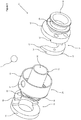
- FIG. 1 shows a side representation of a first embodiment of a rotary introducer in accordance with the first aspect of the invention
- FIG. 2 shows an exploded perspective representation of the rotary introducer of FIG. 1 ;
- FIG. 3 shows a perspective representation of the rotary introducer of FIG. 1 , the driving and drivable members being in their respective start positions, with an introducer housing of the rotary introducer being transparent for clarity;
- FIG. 4 shows an end view of the rotary introducer of FIG. 1 , the introducer housing of the rotary introducer being transparent for clarity;
- FIG. 5 a shows a diametric cross-section through the rotary introducer of FIG. 1 , indicating the trackable element and/or contaminant being inserted into the inlet of the rotary introducer in the trackable-element receiving condition;
- FIG. 5 b shows a diametric cross-section through the rotary introducer of FIG. 1 , indicating the trackable element and/or contaminant having been received in the device cavity;
- FIG. 5 c shows a diametric cross-section through the rotary introducer of FIG. 1 , following a clockwise rotation of the driving member of the rotary introducer;
- FIG. 5 d shows a diametric cross-section through the rotary introducer of FIG. 1 , following a further clockwise rotation of the driving member of the rotary introducer, such that the rotary introducer is in the trackable-element discharge condition;
- FIGS. 5 e and 5 f show diametric cross-sections through the rotary introducer of FIG. 1 , following incremental sequential clockwise rotations of the driving member of the rotary introducer;
- FIG. 5 g shows a diametric cross-section through the rotary introducer of FIG. 1 , following complete clockwise rotation of the driving member such that the first and second device-contact surfaces are coincident;
- FIG. 5 h shows a diametric cross-section through the rotary introducer of FIG. 1 , following anti-clockwise rotation of the driving member in co-operation with the drivable member;
- FIG. 5 i shows a diametric cross-section through the rotary introducer of FIG. 1 , following further anti-clockwise rotation of the driving member having released the drivable member, to return the rotary introducer to the trackable-element receiving condition;
- FIG. 6 shows a perspective representation of a second embodiment of a rotary introducer in accordance with the first aspect of the invention.
- FIG. 1 there is illustrated a rotary introducer, indicated globally at 10 for the introduction of a trackable device 12 , which in this case is a trackable element and/or contaminant, onto a flow path of a food-transit system without adjusting a flowrate of a liquid or semi-liquid foodstuff being transported therethrough.
- a trackable device 12 which in this case is a trackable element and/or contaminant
- the rotary introducer 10 comprises a rotatable driving member 14 and a rotatable drivable member 16 which are mutually co-operable with one another. These components can be seen in FIG. 2 .
- the driving and drivable members 14 , 16 are positionable about a food-transit conduit 18 , which is here associated with, and may be preferably integrally formed with, an introducer housing 20 within which the driving and drivable members 14 , 16 are housable so as to be rotatably movable about the food-transit conduit 18 .
- an inlet port 24 which permits access to an inlet 26 of the rotary introducer 10 when in a trackable-element receiving condition. This can be seen in FIG. 3 ; the circumferential wall 22 of the introducer housing being shown to be transparent to illustrate the inlet 26 .
- an outlet port 28 to allow the trackable device to be inserted into a flow path which passes through the bore 30 of the food-transit conduit 18 .
- an outlet 32 of the rotary introducer will open adjacent to the outlet port 28 , and this will be discussed in detail below.
- the inlet 26 and outlet 32 are angularly displaced from one another, preferably by between 90 and 180 degrees, with the outlet 32 being radially-inwardly disposed of the inlet 26 .
- the introducer housing 20 may be formed having an end cap 34 against which one or other of the driving and drivable member 14 , 16 may abut, and the external circumferential wall 22 may extend around the full circumference of the food-transit conduit 18 to retain the driving and drivable members 14 , 16 in position.
- a housing flange portion 36 which is engagable around the food-transit conduit 18 and which abuts against the driving member 14 to retain it inside the introducer housing 20 .
- This has an end flange 38 which allows the rotary introducer 10 as a whole to be coupled to a food-transit pipe network.
- An opposing end of the food-transit conduit 18 may also be formed so as to have a connecting flange 40 .
- rotary introducer 10 indicates a simplified version of the introducer housing 20 .
- the driving and drivable member 14 , 16 are preferably encasable within an introducer housing, such that both of the driving and drivable member 14 , 16 abut an end cap thereof. Bearings which couple to the end caps may be provided to improve the freedom of rotation of the driving and drivable members 14 , 16 with respect to the introducer housing.
- the introducer housing will also be provided with a means by which the driving member 14 , at least, can be rotated, via a drive engagement means.
- a means by which the driving member 14 can be rotated, via a drive engagement means.
- This could be provided, for example by magnetic engagement with a magnetic drive, if the driving member 14 were sufficiently magnetic or magnetisable, or there could be a cut-out portion of the introducer housing 20 to allow for coupling of a ring gear associated with the driving member 14 to a gear-toothed coupling shaft, which could be in turn connected to a motor.
- the driving member 14 could be accessible to the user for manual actuation, as would be the case for the depicted embodiment.
- the driving member 14 and drivable member 16 are formed as two parts of a hollow cylinder, preferably being formed such that each comprises a, preferably disciform, base portion 42 , 44 and a, preferably substantially hemi-cylindrical, stepped portion 46 , 48 which projects from the respective base portion 42 , 44 .
- the base portions 42 , 44 and the stepped portions 46 , 48 may be manufactured separately for simplicity, but it will be apparent that each of the driving and drivable members 14 , 16 could be formed as a single unitary piece.
- the driving member 14 is formed such that the stepped portion 46 , when attached to the base portion 42 , has a projecting armature 50 which preferably projects in a plane of the base portion 42 out of step wall 52 of the stepped portion 46 , and the armature 50 preferably has a wedge- or triangular-shaped profile. In the depicted embodiment, there is space around either side of the projecting armature 50 , but could feasibly be formed more as a shoulder projecting from the base portion 42 .
- the drivable member 16 is formed having a complementary shape to the driving member 14 , such that the two stepped portions 46 , 48 can be engaged together to complete the cylinder formed by the driving and drivable members 14 , 16 .
- the engagement of the base portion 44 and the stepped portion 48 of the drivable member 16 is such that a complementary recess 54 is formed within which the projecting armature 50 of the driving member 14 is receivable.
- the receivable portions of the driving and drivable member 14 , 16 which in this instance are the armature 50 and complementary recess 54 , may be magnetically interengagable such that, when the armature 50 is received within the recess 54 , the driving and drivable members 14 , 16 latch to one another magnetically.
- the driving and drivable members 14 , 16 Whilst the driving and drivable members 14 , 16 are described as forming a cylinder when engaged with one another, they do not completely tessellate; there is a mismatch between the sizes of the stepped portions 46 , 48 which allows for rotation between the driving and drivable members 14 , 16 to occur. This effectively forms a device cavity 56 within which the trackable device 12 can be introduced into the rotary introducer 10 during use.
- the device cavity 56 can be seen in particular in FIG. 3 of the drawings.
- the specific arrangement of the driving and drivable members 14 , 16 is such that the armature 50 of the driving member 14 is receivable within the complementary recess 54 of the drivable member 16 .
- bearings may be provided to facilitate rotational engagement between the driving and drivable members 14 , 16 of the rotary introducer 10 .
- Similar and complementary bearing receivers may be provided on the driving member 14 if applicable.
- FIG. 4 shows the end cap 34 of the introducer housing 20 .
- a projecting pin or stop 60 may be provided on the base portion 44 of the drivable member 16 which is engagable with a corresponding, preferably arcuate, slot 62 in the end cap 34 .
- the correspondence between the stop 60 and slot 62 may define the rotational minimum and maximum positions for the drivable member 16 , as the stop 60 abuts or is stopped by the first or second end 64 , 66 of the slot 62 .
- the rotary introducer 10 can be utilised to insert a trackable device 12 into a pipe of a food-transit system, preferably via the food-transit conduit 18 .
- the process by which this occurs is depicted in detail in FIGS. 5 a to 5 i .
- a cross-section through the rotary introducer 10 is illustrated in each case, with the positions of the respective stepped portions 46 , 48 of the driving and drivable members 14 , 16 being visible in each case.
- each stepped portion 46 , 48 the surfaces are complementarily shaped, such that the driving member 14 can engage with the drivable member 16 .
- These ends 68 , 70 may be aligned to a radius of the rotary introducer 10 , as illustrated.
- the armature 50 and complementary recess 54 are the armature 50 and complementary recess 54 respectively.
- the outermost surface of each respectively forms first and second device-contact surfaces 72 , 74 .
- the inlet 26 is open to receive the trackable device 12 in the device cavity 56 due to the first and second device-contact surfaces 72 , 74 of the driving and drivable members 14 , 16 being in angularly displaced driving-member and drivable-member start positions respectively, with the outlet is closed by at least one of the driving and drivable member 14 , 16 , here the drivable member 16 .
- FIG. 5 a therefore represents a trackable-element receiving condition of the rotary introducer 10 , with the driving and drivable members 14 , 16 having the first and second device-contact surfaces 72 , 74 respectively in driving-member and drivable-member start positions to define the inlet 26 .
- the inlet 26 is, in the depicted embodiment, aligned with the inlet port 24 of the introducer housing 20 .
- the trackable device 12 has been introduced into the device cavity 56 , and the first and second device-contact surfaces 72 , 74 are positioned so as to be in contact or near-contact with the sides of the trackable device 12 .
- FIG. 5 c shows a clockwise rotation of the driving member 14 .
- the trackable device 12 having been received into the device cavity 56 , is sandwiched between the first and second device-contact surfaces 72 , 74 , such that a rotational force is imparted from the driving member 14 through the trackable device 12 to the drivable member 16 .
- Driving the driving member 14 therefore results in an indirect actuation of the drivable member 16 .
- FIG. 5 d A further clockwise rotation of the driving member 14 is illustrated in FIG. 5 d .
- the drivable member 16 has rotated sufficiently that the stop 60 of the drivable member 16 (as shown in FIG. 4 ) will have contacted the first end 64 of the slot 62 of the introducer housing 20 , preventing further clockwise rotation of the drivable member 16 .
- the trackable device 12 offers some physical resistance; however, the shapes of the first and second device-contact surfaces 72 , 74 are such that a trackable-element discharge force is applied to the trackable device 12 in a radially-inward direction, towards and through the outlet 32 and/or outlet port 28 as the first and second device-contact surfaces 72 , 74 are brought into coincidence.
- This trackable-element discharge force is achieved here by providing the first and second device-contact surfaces 72 , 74 so as to be radially convergent, that is, substantially forming a substantially trapezoidally-shaped device cavity 56 of decreasing volume as the first device-contact surface 72 advances towards the second device-contact surface 74 .
- This provides a simple way of creating a radially-inwardly directed force to push or urge the trackable device 12 through the outlet 32 . This can be readily seen in FIG. 5 e.
- FIG. 5 f With the trackable device 12 discharged into the food-transit conduit 18 , as illustrated in FIG. 5 f , the driving member 14 can continue to rotate in a clockwise direction.
- the projecting armature 50 is received into the complementary recess 54 of the drivable member 16 , which allows for continued rotation of the driving member 14 .
- FIG. 5 f therefore indicates a trackable-element discharge condition of the rotary introducer 10 , since the first and second device-contact surfaces 72 , 74 are or are substantially coincident with one another.
- a continued rotation of the driving member 14 results in closure of the outlet 32 of the rotary introducer 10 .
- This prevents or limits reflux of foodstuffs from the food-transit conduit 18 into the device cavity 56 .
- the step wall 52 of the driving member 14 abuts the second device-contact surface 74 of the drivable member 16 , preventing further clockwise rotation of the driving member 14 .
- This therefore represents a driving-member stop position for the driving member 14 , in which the outlet 32 is closed.
- the driving and drivable members 14 , 16 will engage with one another at this point, and this may be achieved by magnetic coupling of the driving and drivable members 14 , 16 .
- This allows for the driving and drivable members 14 , 16 to be rotated in an anti-clockwise direction together, without necessarily providing a physical coupling between the two.
- the anti-clockwise rotation of the driving member 14 effectively pulls the magnetically-engaged drivable member 16 in an anti-clockwise direction. This can be seen in FIG. 5 h , and shows how the outlet port 28 remains closed despite the anti-clockwise rotation of the driving and drivable members 14 , 16 .
- a recoil or return mechanism may be provided which is different to the driving means by which the driving member 14 is actuated, such as a coiled-spring return element.
- a unidirectional drive means to be provided to actuate the driving member 14 in a clockwise direction, such as a worm gear.
- the position of the drivable member 16 in FIG. 5 h represents a return to the drivable-member start position; the stop 60 of the drivable member 16 is now in contact with the second end 66 of the slot 62 of the introducer housing 20 , and therefore further anti-clockwise rotation is prevented. Continued anti-clockwise rotation of the driving member 14 therefore disengages the magnetic connection between the driving and drivable members 14 , 16 .
- FIG. 5 i in which the driving member 14 has been returned to the driving-member start position, having de-latched from the drivable member 16 which remains in the drivable-member start position.
- the rotary introducer 10 is now in a suitable condition for insertion of another trackable device 12 , without the flow of the food-transit system having been interrupted.
- a pipe of a food-transit pipe network could be replaced with the food-transit conduit 18 of the rotary introducer 10 .
- the food-transit conduit could be dispensed with, and the driving and drivable members 14 , 16 could be coupled directly around an existing pipe of the food-transit pipe network which has an outlet.
- end and connecting flanges 36 , 38 may be provided so as to be magnetically-engagable with corresponding flanges on the food-transit pipe network.
- FIG. 6 A second embodiment of a rotary introducer is illustrated in FIG. 6 , and is indicated globally at 110 .
- Identical or similar components to that of the first aspect of the invention are referred to using identical or similar reference numerals, and further detailed description is therefore omitted for brevity.
- This embodiment of rotary introducer 110 is largely similar to that of the first embodiment, other than the driving and drivable members 114 , 116 are unitarily formed, for example, being moulded from a single piece of plastics material, or could be 3 D printed.
- the introducer housing 120 is sized so as to only cover part of the driving and drivable members 114 , 116 about the food-transit conduit 118 ; the circumferential wall 122 extends around approximately 180 degrees about the food-transit conduit 118 , which provides a greater degree of access to the driving and drivable members 114 , 116 . Such an arrangement may therefore be more suitable for manual actuation of the driving member 114 in particular.
- the mechanism by which the rotational minimum and maximum positions of the drivable member is created may not necessarily be provided by a stop.
- a lip or rim inside the introducer housing could be used to limit the rotational movement of the drivable member.
- the provision of a synchronised driving force could also remove the need for a stop entirely.
- Magnetic latching between the driving and drivable members is not the only means by which the reversing of the rotary introducer may be achieved.
- the return mechanism alluded to above could be coupled directly to the drivable member to encourage return to the drivable member start position in use.
- any other suitable urging means or urging mechanism preferably being rotatable but not necessarily limited to such, may be considered.
- a plunger mechanism to press the trackable element/contaminant into the flowing food stuff, and/or a compressed-gas discharge mechanism to fire the trackable element/contaminant into the flowing food stuff may be feasibly considered.
- a rotary introducer which is capable of introducing a trackable element and/or contaminant into a food-transit system without adjusting a flowrate of the system.
- first and second rotatable members which are preferably a master and slave, driving and drivable members respectively.
- the trackable element and/or contaminant can be clasped between the two rotatable members in such a manner as to encourage insertion of the trackable element and/or contaminant into the flow path of the food-transit system once aligned with an outlet of the rotary introducer.
- Continued rotation of the rotatable members then allows the outlet to be shut off, without resulting in reflux of the material in the food-transit system back into the rotary introducer.
Landscapes
- Engineering & Computer Science (AREA)
- General Engineering & Computer Science (AREA)
- Mechanical Engineering (AREA)
- Life Sciences & Earth Sciences (AREA)
- Combustion & Propulsion (AREA)
- Chemical & Material Sciences (AREA)
- Food Science & Technology (AREA)
- Wood Science & Technology (AREA)
- Zoology (AREA)
- Health & Medical Sciences (AREA)
- Water Supply & Treatment (AREA)
- Public Health (AREA)
- Food-Manufacturing Devices (AREA)
Abstract
Description
Claims (20)
Applications Claiming Priority (2)
| Application Number | Priority Date | Filing Date | Title |
|---|---|---|---|
| GB1620678.1A GB2547074B (en) | 2016-12-05 | 2016-12-05 | Rotary introducer |
| GB1620678.1 | 2016-12-05 |
Publications (2)
| Publication Number | Publication Date |
|---|---|
| US20180156391A1 US20180156391A1 (en) | 2018-06-07 |
| US10711948B2 true US10711948B2 (en) | 2020-07-14 |
Family
ID=58159815
Family Applications (1)
| Application Number | Title | Priority Date | Filing Date |
|---|---|---|---|
| US15/830,521 Active 2038-10-30 US10711948B2 (en) | 2016-12-05 | 2017-12-04 | Rotary introducer |
Country Status (3)
| Country | Link |
|---|---|
| US (1) | US10711948B2 (en) |
| EP (1) | EP3330589B1 (en) |
| GB (1) | GB2547074B (en) |
Families Citing this family (1)
| Publication number | Priority date | Publication date | Assignee | Title |
|---|---|---|---|---|
| CN120027359B (en) * | 2025-01-23 | 2025-12-19 | 陕西能源凉水井矿业有限责任公司 | A long-distance, wash-free pipeline system for conveying gangue slurry and its application method |
Citations (7)
| Publication number | Priority date | Publication date | Assignee | Title |
|---|---|---|---|---|
| US3715055A (en) * | 1971-06-16 | 1973-02-06 | Halliburton Co | Apparatus for injecting one or more articles individually into a tubular flow path |
| US4491177A (en) | 1982-07-06 | 1985-01-01 | Hughes Tool Company | Ball dropping assembly |
| GB2340861A (en) | 1998-07-14 | 2000-03-01 | Baker Hughes Inc | Multi-port cementing head |
| US20110120499A1 (en) | 2009-11-24 | 2011-05-26 | Pruett Rick D | Method and System for an Injectable Foam Pig |
| EP2581169A1 (en) | 2011-10-14 | 2013-04-17 | bedeko GmbH | Metering device |
| GB2515319A (en) | 2013-06-19 | 2014-12-24 | Priden Engineering Ltd | Method & apparatus for introducing a foreign object into a pipeline through which a product is flowing under pressure |
| US20150068727A1 (en) | 2013-09-06 | 2015-03-12 | Baker Hughes Incorporated | Subterranean Tool for Release of Balls Adjacent Their Intended Destinations |
-
2016
- 2016-12-05 GB GB1620678.1A patent/GB2547074B/en active Active
-
2017
- 2017-12-04 US US15/830,521 patent/US10711948B2/en active Active
- 2017-12-04 EP EP17205272.2A patent/EP3330589B1/en active Active
Patent Citations (7)
| Publication number | Priority date | Publication date | Assignee | Title |
|---|---|---|---|---|
| US3715055A (en) * | 1971-06-16 | 1973-02-06 | Halliburton Co | Apparatus for injecting one or more articles individually into a tubular flow path |
| US4491177A (en) | 1982-07-06 | 1985-01-01 | Hughes Tool Company | Ball dropping assembly |
| GB2340861A (en) | 1998-07-14 | 2000-03-01 | Baker Hughes Inc | Multi-port cementing head |
| US20110120499A1 (en) | 2009-11-24 | 2011-05-26 | Pruett Rick D | Method and System for an Injectable Foam Pig |
| EP2581169A1 (en) | 2011-10-14 | 2013-04-17 | bedeko GmbH | Metering device |
| GB2515319A (en) | 2013-06-19 | 2014-12-24 | Priden Engineering Ltd | Method & apparatus for introducing a foreign object into a pipeline through which a product is flowing under pressure |
| US20150068727A1 (en) | 2013-09-06 | 2015-03-12 | Baker Hughes Incorporated | Subterranean Tool for Release of Balls Adjacent Their Intended Destinations |
Non-Patent Citations (4)
| Title |
|---|
| English translation of EP2581169, 15 pp. |
| European Search Report for EP 17 20 5272 dated Apr. 24, 2018, 4 pp. |
| Examination Report for GB 1620678.1 dated Jul. 19, 2017, 1 pp. |
| Search Report for GB 1620678.1 dated May 24, 2017, 1 pp. |
Also Published As
| Publication number | Publication date |
|---|---|
| US20180156391A1 (en) | 2018-06-07 |
| GB2547074B (en) | 2018-06-20 |
| GB201620678D0 (en) | 2017-01-18 |
| EP3330589A1 (en) | 2018-06-06 |
| GB2547074A (en) | 2017-08-09 |
| EP3330589B1 (en) | 2019-09-04 |
Similar Documents
| Publication | Publication Date | Title |
|---|---|---|
| US8596316B2 (en) | Coupling closure, and docking device comprising two of said coupling closures | |
| US2905197A (en) | Three-way ball valve | |
| US8740187B2 (en) | Split valve | |
| US10711948B2 (en) | Rotary introducer | |
| US8539995B2 (en) | Coupling lock and attachment module and docking device, each containing said coupling lock | |
| US5002084A (en) | Quick clean rotary valve | |
| EP2988044A1 (en) | Shutter valve with pivot arms | |
| US20150027563A1 (en) | Valves | |
| US8813795B2 (en) | Passive valve for multivalve devices and a multivalve device, in particular having such a passive valve | |
| US9404785B2 (en) | Retractable assembly for immersion-, flow- and attachment-measuring systems | |
| JP5773297B1 (en) | Rotary joint and mechanical seal monitoring device including the same | |
| CN112888884A (en) | Valve with a valve body | |
| CN113710413B (en) | Bending assembly for a cover | |
| US9945485B2 (en) | Seal assembly for a sterile environment | |
| GB2548329A (en) | Removable self-centring magnetically-clampable food-inspection pipe apparatus | |
| EP3583065B1 (en) | Delivering tap with cam-and-follower-type opening mechanism | |
| CN114321426B (en) | Plug valve and water air conditioner | |
| WO2020124245A1 (en) | Systems and methods for a reusable, aseptic connector | |
| KR20170053643A (en) | Housing for a device for the metered distribution of a medium, and metering device for use in said housing | |
| US12422597B2 (en) | Closure mechanism | |
| JP7570593B2 (en) | Sealed container with bi-material flange | |
| US5257772A (en) | Butterfly valve | |
| US8783524B2 (en) | Valve device for a pasty food product volumetric metering apparatus, and volumetric metering apparatus | |
| US4722508A (en) | Valve on processing plant | |
| EP4559358A1 (en) | Application device |
Legal Events
| Date | Code | Title | Description |
|---|---|---|---|
| FEPP | Fee payment procedure |
Free format text: ENTITY STATUS SET TO UNDISCOUNTED (ORIGINAL EVENT CODE: BIG.); ENTITY STATUS OF PATENT OWNER: SMALL ENTITY |
|
| FEPP | Fee payment procedure |
Free format text: ENTITY STATUS SET TO SMALL (ORIGINAL EVENT CODE: SMAL); ENTITY STATUS OF PATENT OWNER: SMALL ENTITY |
|
| AS | Assignment |
Owner name: SPARC SYSTEMS LIMITED, GREAT BRITAIN Free format text: ASSIGNMENT OF ASSIGNORS INTEREST;ASSIGNORS:BUCKLEY, DAVID;REYNOLDS, DAVID;IVES, JONATHAN;REEL/FRAME:045176/0659 Effective date: 20180129 |
|
| STPP | Information on status: patent application and granting procedure in general |
Free format text: DOCKETED NEW CASE - READY FOR EXAMINATION |
|
| STPP | Information on status: patent application and granting procedure in general |
Free format text: NON FINAL ACTION MAILED |
|
| STPP | Information on status: patent application and granting procedure in general |
Free format text: RESPONSE TO NON-FINAL OFFICE ACTION ENTERED AND FORWARDED TO EXAMINER |
|
| STPP | Information on status: patent application and granting procedure in general |
Free format text: NON FINAL ACTION MAILED |
|
| STPP | Information on status: patent application and granting procedure in general |
Free format text: NOTICE OF ALLOWANCE MAILED -- APPLICATION RECEIVED IN OFFICE OF PUBLICATIONS |
|
| STPP | Information on status: patent application and granting procedure in general |
Free format text: PUBLICATIONS -- ISSUE FEE PAYMENT VERIFIED |
|
| STCF | Information on status: patent grant |
Free format text: PATENTED CASE |
|
| AS | Assignment |
Owner name: FORTRESS TECHNOLOGY (EUROPE) LIMITED, UNITED KINGDOM Free format text: ASSIGNMENT OF ASSIGNORS INTEREST;ASSIGNOR:SPARC SYSTEMS LIMITED;REEL/FRAME:064534/0348 Effective date: 20230808 |
|
| MAFP | Maintenance fee payment |
Free format text: PAYMENT OF MAINTENANCE FEE, 4TH YR, SMALL ENTITY (ORIGINAL EVENT CODE: M2551); ENTITY STATUS OF PATENT OWNER: SMALL ENTITY Year of fee payment: 4 |