US10710602B2 - Systems and methods for a vehicle controller safety monitor - Google Patents
Systems and methods for a vehicle controller safety monitor Download PDFInfo
- Publication number
- US10710602B2 US10710602B2 US15/810,495 US201715810495A US10710602B2 US 10710602 B2 US10710602 B2 US 10710602B2 US 201715810495 A US201715810495 A US 201715810495A US 10710602 B2 US10710602 B2 US 10710602B2
- Authority
- US
- United States
- Prior art keywords
- vehicle
- failure mode
- vehicle controller
- mode exists
- message
- Prior art date
- Legal status (The legal status is an assumption and is not a legal conclusion. Google has not performed a legal analysis and makes no representation as to the accuracy of the status listed.)
- Active, expires
Links
Images


Classifications
-
- B—PERFORMING OPERATIONS; TRANSPORTING
- B60—VEHICLES IN GENERAL
- B60W—CONJOINT CONTROL OF VEHICLE SUB-UNITS OF DIFFERENT TYPE OR DIFFERENT FUNCTION; CONTROL SYSTEMS SPECIALLY ADAPTED FOR HYBRID VEHICLES; ROAD VEHICLE DRIVE CONTROL SYSTEMS FOR PURPOSES NOT RELATED TO THE CONTROL OF A PARTICULAR SUB-UNIT
- B60W50/00—Details of control systems for road vehicle drive control not related to the control of a particular sub-unit, e.g. process diagnostic or vehicle driver interfaces
- B60W50/04—Monitoring the functioning of the control system
-
- B—PERFORMING OPERATIONS; TRANSPORTING
- B60—VEHICLES IN GENERAL
- B60W—CONJOINT CONTROL OF VEHICLE SUB-UNITS OF DIFFERENT TYPE OR DIFFERENT FUNCTION; CONTROL SYSTEMS SPECIALLY ADAPTED FOR HYBRID VEHICLES; ROAD VEHICLE DRIVE CONTROL SYSTEMS FOR PURPOSES NOT RELATED TO THE CONTROL OF A PARTICULAR SUB-UNIT
- B60W30/00—Purposes of road vehicle drive control systems not related to the control of a particular sub-unit, e.g. of systems using conjoint control of vehicle sub-units
-
- B—PERFORMING OPERATIONS; TRANSPORTING
- B60—VEHICLES IN GENERAL
- B60W—CONJOINT CONTROL OF VEHICLE SUB-UNITS OF DIFFERENT TYPE OR DIFFERENT FUNCTION; CONTROL SYSTEMS SPECIALLY ADAPTED FOR HYBRID VEHICLES; ROAD VEHICLE DRIVE CONTROL SYSTEMS FOR PURPOSES NOT RELATED TO THE CONTROL OF A PARTICULAR SUB-UNIT
- B60W50/00—Details of control systems for road vehicle drive control not related to the control of a particular sub-unit, e.g. process diagnostic or vehicle driver interfaces
- B60W50/02—Ensuring safety in case of control system failures, e.g. by diagnosing, circumventing or fixing failures
- B60W50/0205—Diagnosing or detecting failures; Failure detection models
-
- B—PERFORMING OPERATIONS; TRANSPORTING
- B60—VEHICLES IN GENERAL
- B60W—CONJOINT CONTROL OF VEHICLE SUB-UNITS OF DIFFERENT TYPE OR DIFFERENT FUNCTION; CONTROL SYSTEMS SPECIALLY ADAPTED FOR HYBRID VEHICLES; ROAD VEHICLE DRIVE CONTROL SYSTEMS FOR PURPOSES NOT RELATED TO THE CONTROL OF A PARTICULAR SUB-UNIT
- B60W50/00—Details of control systems for road vehicle drive control not related to the control of a particular sub-unit, e.g. process diagnostic or vehicle driver interfaces
- B60W50/02—Ensuring safety in case of control system failures, e.g. by diagnosing, circumventing or fixing failures
- B60W50/029—Adapting to failures or work around with other constraints, e.g. circumvention by avoiding use of failed parts
-
- B—PERFORMING OPERATIONS; TRANSPORTING
- B60—VEHICLES IN GENERAL
- B60W—CONJOINT CONTROL OF VEHICLE SUB-UNITS OF DIFFERENT TYPE OR DIFFERENT FUNCTION; CONTROL SYSTEMS SPECIALLY ADAPTED FOR HYBRID VEHICLES; ROAD VEHICLE DRIVE CONTROL SYSTEMS FOR PURPOSES NOT RELATED TO THE CONTROL OF A PARTICULAR SUB-UNIT
- B60W60/00—Drive control systems specially adapted for autonomous road vehicles
- B60W60/005—Handover processes
- B60W60/0053—Handover processes from vehicle to occupant
-
- B—PERFORMING OPERATIONS; TRANSPORTING
- B60—VEHICLES IN GENERAL
- B60W—CONJOINT CONTROL OF VEHICLE SUB-UNITS OF DIFFERENT TYPE OR DIFFERENT FUNCTION; CONTROL SYSTEMS SPECIALLY ADAPTED FOR HYBRID VEHICLES; ROAD VEHICLE DRIVE CONTROL SYSTEMS FOR PURPOSES NOT RELATED TO THE CONTROL OF A PARTICULAR SUB-UNIT
- B60W60/00—Drive control systems specially adapted for autonomous road vehicles
- B60W60/005—Handover processes
- B60W60/0059—Estimation of the risk associated with autonomous or manual driving, e.g. situation too complex, sensor failure or driver incapacity
-
- G—PHYSICS
- G05—CONTROLLING; REGULATING
- G05D—SYSTEMS FOR CONTROLLING OR REGULATING NON-ELECTRIC VARIABLES
- G05D1/00—Control of position, course, altitude or attitude of land, water, air or space vehicles, e.g. using automatic pilots
- G05D1/0055—Control of position, course, altitude or attitude of land, water, air or space vehicles, e.g. using automatic pilots with safety arrangements
-
- G—PHYSICS
- G05—CONTROLLING; REGULATING
- G05D—SYSTEMS FOR CONTROLLING OR REGULATING NON-ELECTRIC VARIABLES
- G05D1/00—Control of position, course, altitude or attitude of land, water, air or space vehicles, e.g. using automatic pilots
- G05D1/0088—Control of position, course, altitude or attitude of land, water, air or space vehicles, e.g. using automatic pilots characterized by the autonomous decision making process, e.g. artificial intelligence, predefined behaviours
-
- G—PHYSICS
- G05—CONTROLLING; REGULATING
- G05D—SYSTEMS FOR CONTROLLING OR REGULATING NON-ELECTRIC VARIABLES
- G05D1/00—Control of position, course, altitude or attitude of land, water, air or space vehicles, e.g. using automatic pilots
- G05D1/02—Control of position or course in two dimensions
- G05D1/021—Control of position or course in two dimensions specially adapted to land vehicles
- G05D1/0212—Control of position or course in two dimensions specially adapted to land vehicles with means for defining a desired trajectory
- G05D1/0214—Control of position or course in two dimensions specially adapted to land vehicles with means for defining a desired trajectory in accordance with safety or protection criteria, e.g. avoiding hazardous areas
-
- G—PHYSICS
- G06—COMPUTING OR CALCULATING; COUNTING
- G06F—ELECTRIC DIGITAL DATA PROCESSING
- G06F11/00—Error detection; Error correction; Monitoring
-
- G—PHYSICS
- G06—COMPUTING OR CALCULATING; COUNTING
- G06F—ELECTRIC DIGITAL DATA PROCESSING
- G06F11/00—Error detection; Error correction; Monitoring
- G06F11/07—Responding to the occurrence of a fault, e.g. fault tolerance
- G06F11/0703—Error or fault processing not based on redundancy, i.e. by taking additional measures to deal with the error or fault not making use of redundancy in operation, in hardware, or in data representation
- G06F11/0706—Error or fault processing not based on redundancy, i.e. by taking additional measures to deal with the error or fault not making use of redundancy in operation, in hardware, or in data representation the processing taking place on a specific hardware platform or in a specific software environment
- G06F11/0715—Error or fault processing not based on redundancy, i.e. by taking additional measures to deal with the error or fault not making use of redundancy in operation, in hardware, or in data representation the processing taking place on a specific hardware platform or in a specific software environment in a system implementing multitasking
-
- G—PHYSICS
- G06—COMPUTING OR CALCULATING; COUNTING
- G06F—ELECTRIC DIGITAL DATA PROCESSING
- G06F11/00—Error detection; Error correction; Monitoring
- G06F11/07—Responding to the occurrence of a fault, e.g. fault tolerance
- G06F11/0703—Error or fault processing not based on redundancy, i.e. by taking additional measures to deal with the error or fault not making use of redundancy in operation, in hardware, or in data representation
- G06F11/0706—Error or fault processing not based on redundancy, i.e. by taking additional measures to deal with the error or fault not making use of redundancy in operation, in hardware, or in data representation the processing taking place on a specific hardware platform or in a specific software environment
- G06F11/0736—Error or fault processing not based on redundancy, i.e. by taking additional measures to deal with the error or fault not making use of redundancy in operation, in hardware, or in data representation the processing taking place on a specific hardware platform or in a specific software environment in functional embedded systems, i.e. in a data processing system designed as a combination of hardware and software dedicated to performing a certain function
- G06F11/0739—Error or fault processing not based on redundancy, i.e. by taking additional measures to deal with the error or fault not making use of redundancy in operation, in hardware, or in data representation the processing taking place on a specific hardware platform or in a specific software environment in functional embedded systems, i.e. in a data processing system designed as a combination of hardware and software dedicated to performing a certain function in a data processing system embedded in automotive or aircraft systems
-
- G—PHYSICS
- G06—COMPUTING OR CALCULATING; COUNTING
- G06F—ELECTRIC DIGITAL DATA PROCESSING
- G06F11/00—Error detection; Error correction; Monitoring
- G06F11/07—Responding to the occurrence of a fault, e.g. fault tolerance
- G06F11/0703—Error or fault processing not based on redundancy, i.e. by taking additional measures to deal with the error or fault not making use of redundancy in operation, in hardware, or in data representation
- G06F11/0751—Error or fault detection not based on redundancy
- G06F11/0754—Error or fault detection not based on redundancy by exceeding limits
- G06F11/0757—Error or fault detection not based on redundancy by exceeding limits by exceeding a time limit, i.e. time-out, e.g. watchdogs
-
- B—PERFORMING OPERATIONS; TRANSPORTING
- B60—VEHICLES IN GENERAL
- B60W—CONJOINT CONTROL OF VEHICLE SUB-UNITS OF DIFFERENT TYPE OR DIFFERENT FUNCTION; CONTROL SYSTEMS SPECIALLY ADAPTED FOR HYBRID VEHICLES; ROAD VEHICLE DRIVE CONTROL SYSTEMS FOR PURPOSES NOT RELATED TO THE CONTROL OF A PARTICULAR SUB-UNIT
- B60W50/00—Details of control systems for road vehicle drive control not related to the control of a particular sub-unit, e.g. process diagnostic or vehicle driver interfaces
- B60W50/02—Ensuring safety in case of control system failures, e.g. by diagnosing, circumventing or fixing failures
- B60W50/0205—Diagnosing or detecting failures; Failure detection models
- B60W2050/021—Means for detecting failure or malfunction
-
- G05D2201/0213—
-
- G—PHYSICS
- G06—COMPUTING OR CALCULATING; COUNTING
- G06F—ELECTRIC DIGITAL DATA PROCESSING
- G06F11/00—Error detection; Error correction; Monitoring
- G06F11/07—Responding to the occurrence of a fault, e.g. fault tolerance
- G06F11/0703—Error or fault processing not based on redundancy, i.e. by taking additional measures to deal with the error or fault not making use of redundancy in operation, in hardware, or in data representation
- G06F11/0793—Remedial or corrective actions
-
- G—PHYSICS
- G06—COMPUTING OR CALCULATING; COUNTING
- G06F—ELECTRIC DIGITAL DATA PROCESSING
- G06F11/00—Error detection; Error correction; Monitoring
- G06F11/07—Responding to the occurrence of a fault, e.g. fault tolerance
- G06F11/0796—Safety measures, i.e. ensuring safe condition in the event of error, e.g. for controlling element
Definitions
- the present disclosure relates generally to autonomous vehicles.
- An autonomous vehicle is a vehicle that is capable of sensing its environment and navigating with little to no human input.
- an autonomous vehicle can observe its surrounding environment using a variety of sensors and can attempt to comprehend the environment by performing various processing techniques on data collected by the sensors. This can allow an autonomous vehicle to navigate without human intervention and, in some cases, even omit the use of a human driver altogether. Due to the lack of human intervention in the operation of an autonomous vehicle, monitoring the status of the autonomous vehicle systems, such as a vehicle controller, can be important to the ongoing operation of the autonomous vehicle.
- the system includes one or more processors; and memory storing instructions that, when executed by the one or more processors, cause the one or more processors to perform operations.
- the operations include obtaining a message from a vehicle controller.
- the operations further include, based at least partly on the message, determining whether a failure mode exists.
- the operations further include providing, in response to determining the failure mode exists, one or more commands to implement a safety measure response for the autonomous vehicle.
- Another example aspect of the present disclosure is directed to a computer-implemented method for providing a safety monitor.
- the method includes obtaining, by a computing system comprising one or more computing devices, a message from a vehicle controller.
- the method further includes determining, by the computing system, whether a failure mode exists.
- the method further includes providing, by the computing system in response to determining the failure mode exists, one or more commands to implement a safety measure response for the autonomous vehicle.
- the autonomous vehicle includes a vehicle computing system, the vehicle computing system including one or more processors; and memory storing instructions that, when executed by the one or more processors, cause the one or more processors to perform operations.
- the operations include obtaining a message from a vehicle controller.
- the operations further include determining whether a failure mode exists.
- the operations further include providing, in response to determining the failure mode exists, one or more commands to implement a safety measure response for the autonomous vehicle.
- FIG. 1 depicts a block diagram of an example system for controlling the navigation of a vehicle according to example embodiments of the present disclosure
- FIG. 2 depicts a block diagram of a first example vehicle controller and safety monitor system according to example embodiments of the present disclosure
- FIG. 3 depicts a block diagram of a second example vehicle controller and safety monitor system according to example embodiments of the present disclosure
- FIG. 4 depicts a block diagram of an example controller safety monitor system according to example embodiments of the present disclosure
- FIG. 5 depicts a block diagram of an example controller safety monitor system according to example embodiments of the present disclosure
- FIG. 6 depicts a block diagram of an example task health monitor system according to example embodiments of the present disclosure
- FIGS. 7A-7B depict flowchart diagrams of example operations for monitoring an autonomous vehicle controller according to example embodiments of the present disclosure
- FIG. 8 depicts a flowchart diagram of example operations for monitoring an autonomous vehicle controller or other autonomy subsystem according to example embodiments of the present disclosure.
- FIG. 9 depicts a block diagram of an example computing system according to example embodiments of the present disclosure.
- Example aspects of the present disclosure are directed to monitoring the status of a vehicle controller during operation of an autonomous vehicle.
- the systems and methods of the present disclosure can monitor the outputs of an autonomous vehicle controller and/or other autonomy subsystems.
- the systems and methods of the present disclosure can detect one or more error and/or failure modes for the vehicle controller and/or other subsystems, such as a controller failure and/or the like.
- the systems and methods of the present disclosure can then initiate one or more appropriate responses and/or maneuvers, such as a safe stop or the like.
- a vehicle controller can generate signals to provide for autonomous operation of a vehicle.
- Example aspects of the present disclosure can provide for a safety monitor system that resides between the autonomous vehicle controller and the one or more vehicle interfaces (e.g., vehicle control interfaces for steering, acceleration, braking, and/or the like).
- the safety monitor system can monitor whether signals are being received from the vehicle controller and determine whether there is a potential failure or error mode that may impact autonomous vehicle operation. For example, the safety monitor system can determine the amount of time that has passed since a signal from the vehicle controller has been updated. If the amount of time is greater than a threshold amount of time, the safety monitor system can determine that a failure has occurred and can generate one or more signals to provide for an appropriate response. For example, the safety monitor system can generate one or more commands to execute a safe stop of the vehicle, alert a driver to the failure, and/or disengage the autonomous operation of the vehicle.
- an autonomous vehicle e.g., a ground-based vehicle, air-based vehicle, other vehicle type, etc.
- the autonomous vehicle can include one or more data acquisition systems (e.g., sensors, image capture devices), one or more vehicle computing systems (e.g. for providing autonomous operation), one or more vehicle control systems, (e.g., for controlling acceleration, braking, steering, etc.), and/or the like.
- data acquisition systems e.g., sensors, image capture devices
- vehicle computing systems e.g. for providing autonomous operation
- vehicle control systems e.g., for controlling acceleration, braking, steering, etc.
- the data acquisition system(s) can acquire sensor data (e.g., LIDAR data, radar data, image data, etc.) associated with one or more objects (e.g., pedestrians, vehicles, etc.) that are proximate to the autonomous vehicle and/or sensor data associated with the vehicle path (e.g., path shape, boundaries, markings, etc.).
- the sensor data can include information that describes the location (e.g., in three-dimensional space relative to the autonomous vehicle) of points that correspond to objects within the surrounding environment of the autonomous vehicle (e.g., at one or more times).
- the data acquisition system(s) can provide such sensor data to the vehicle computing system.
- the vehicle computing system can obtain map data that provides other detailed information about the surrounding environment of the autonomous vehicle.
- the map data can provide information regarding: the identity and location of various roadways, road segments, buildings, or other items; the location and direction of traffic lanes (e.g. the boundaries, location, direction, etc. of a travel lane, parking lane, a turning lane, a bicycle lane, and/or other lanes within a particular travel way); traffic control data (e.g., the location and instructions of signage, traffic signals, and/or other traffic control devices); and/or any other map data that provides information that can assist the autonomous vehicle in comprehending and perceiving its surrounding environment and its relationship thereto.
- traffic lanes e.g. the boundaries, location, direction, etc. of a travel lane, parking lane, a turning lane, a bicycle lane, and/or other lanes within a particular travel way
- traffic control data e.g., the location and instructions of signage, traffic signals, and/or other traffic control devices
- the vehicle computing system can include one or more computing devices and include various subsystems that can cooperate to perceive the surrounding environment of the autonomous vehicle and determine a motion plan for controlling the motion of the autonomous vehicle.
- the vehicle computing system can include a perception system, a prediction system, and a motion planning system.
- the vehicle computing system can receive and process the sensor data to generate an appropriate motion plan through the vehicle's surrounding environment.
- the perception system can detect one or more objects that are proximate to the autonomous vehicle based on the sensor data.
- the perception system can determine, for each object, state data that describes a current state of such object.
- the state data for each object can describe an estimate of the object's: current location (also referred to as position); current speed/velocity; current acceleration; current heading; current orientation; size/footprint; class (e.g., vehicle class versus pedestrian class versus bicycle class, etc.); and/or other state information.
- the perception system can determine state data for each object over a number of iterations. In particular, the perception system can update the state data for each object at each iteration.
- the perception system can detect and track objects (e.g., vehicles, bicycles, pedestrians, etc.) that are proximate to the autonomous vehicle over time, and thereby produce a presentation of the world around an autonomous vehicle along with its state (e.g., a presentation of the objects within a scene at the current time along with the states of the objects).
- objects e.g., vehicles, bicycles, pedestrians, etc.
- its state e.g., a presentation of the objects within a scene at the current time along with the states of the objects.
- the prediction system can receive the state data from the perception system and predict one or more future locations for each object based on such state data. For example, the prediction system can predict where each object will be located within the next 5 seconds, 10 seconds, 20 seconds, etc. As one example, an object can be predicted to adhere to its current trajectory according to its current speed. As another example, other, more sophisticated prediction techniques or modeling can be used.
- the motion planning system can determine a motion plan for the autonomous vehicle based at least in part on predicted one or more future locations for the object provided by the prediction system and/or the state data for the object provided by the perception system. Stated differently, given information about the classification and current locations of objects and/or predicted future locations of proximate objects, the motion planning system can determine a motion plan for the autonomous vehicle that best navigates the autonomous vehicle along the determined travel route relative to the objects at such locations.
- the motion planning system can determine a cost function for each of one or more candidate motion plans for the autonomous vehicle based at least in part on the current locations and/or predicted future locations of the objects.
- the cost function can describe a cost (e.g., over time) of adhering to a particular candidate motion plan.
- the cost described by a cost function can increase when the autonomous vehicle approaches impact with another object and/or deviates from a preferred pathway (e.g., a predetermined travel route).
- the motion planning system can determine a cost of adhering to a particular candidate pathway.
- the motion planning system can select or determine a motion plan for the autonomous vehicle based at least in part on the cost function(s). For example, the motion plan that minimizes the cost function can be selected or otherwise determined.
- the motion planning system then can provide the selected motion plan to a vehicle controller.
- the vehicle controller can generate one or more commands, based at least in part on the motion plan, which can be provided to one or more vehicle control interfaces.
- the one or more commands from the vehicle controller can provide for operating one or more vehicle controls (e.g., actuators or other devices that control acceleration, throttle, steering, braking, etc.) to execute the selected motion plan.
- vehicle controls e.g., actuators or other devices that control acceleration, throttle, steering, braking, etc.
- example systems and methods of the present disclosure can provide for a safety monitor system that can monitor the output of the vehicle controller and/or another autonomy subsystem (e.g., sensors, prediction, perception, motion planning, and/or the like) and determine whether a failure or error condition has occurred.
- the safety monitor system can maintain a history of previous signals or command messages received from the vehicle controller.
- the safety monitor system can generate a timestamp for each message as it is received.
- the safety monitor system can determine the amount of time that has passed since the last message was received on each successive cycle (e.g., current time minus timestamp of last message).
- the safety monitor can use a timer to measure the time from the last message.
- the safety monitor system can determine if the amount of time that has passed has reached or passed a threshold amount of time, and in response, determine that an error or failure has occurred. Upon determining that a failure or error has occurred in the vehicle controller and/or another subsystem, the safety monitor system can generate one or more commands or signals to initiate a safety response. For example, the safety monitor can generate one or more commands to execute a safe stop of the vehicle, alert a driver to the error/failure, and/or disengage the autonomous operation of the vehicle.
- the safety monitor system can determine whether autonomous operation of the vehicle can be engaged (or should be disengaged if already engaged) based on determining status of the vehicle controller such as whether an error or failure condition exists or not (e.g., whether signals are being received for the vehicle controller and/or another subsystem).
- the safety monitor system can perform the vehicle controller status determination on a periodic rate. For instance, instead of waiting for a message to be received, in some implementations, the safety monitor system can determine that a failure has occurred if no message is received from the vehicle controller.
- the safety monitor system can also monitor whether an autonomous vehicle is ready to engage autonomous operation.
- the safety monitor system can receive a signal indicating whether the vehicle is ready to engage autonomous operation in addition to monitoring the status of the vehicle controller (and/or other subsystems).
- the safety monitor system can determine that the vehicle controller is providing signals or command messages and that the vehicle is ready to engage before allowing a driver to engage the autonomous operation.
- the safety monitor system can provide for different audio alerts corresponding to the decisions being made by the system to be produced for the driver and/or occupants of the vehicle.
- the safety monitor system can provide for different audio alerts to be played when both the vehicle and controller are in the ready state, for a successful engage, for an unsuccessful engage, for a successful disengage, and/or the like.
- the safety monitor system can also provide for one or more visualizations, such as on a device screen, to indicate the current status and/or decision state.
- the vehicle controller, the safety monitor system, and the interfaces to the vehicle are implemented separately to provide for reliability, such that an error mode in the controller is unlikely to cause the safety monitor system to fail for the same reason.
- the vehicle controller performs complex operations, where the safety monitor system is less complex.
- the safety monitor system can be implemented as a state machine having multiple states and transitions from each state to a different state, for example, based on a determination that the time elapsed since a last vehicle control message was received has reached a threshold.
- the vehicle controller and the safety monitor system can be implemented as separate threads on a processor.
- one or more cores of the processor can be isolated for the safety monitor system, for example, to maintain the integrity and robustness of the safety monitor system.
- one core of a multiple core processor can be isolated for the safety monitor system and the remaining cores of the processor can be used for the other subsystems, such that the safety monitor system does not need to compete with the other subsystems for resources.
- the safety monitor system can execute on the isolated core without being interrupted for the execution of other processes.
- the safety monitor system can be implemented using separate hardware (e.g., separate processer(s), etc.) from the vehicle controller (and/or other subsystems) to provide an additional level of robustness. In such implementations, this would provide for the safety monitor system to have its own independent resources and reduce the likelihood that the safety monitor system would fail along with the vehicle controller.
- separate hardware e.g., separate processer(s), etc.
- the safety monitor system can provide for nominal trajectories that can be executed if the vehicle controller fails. For example, after determining that commands are not being received from the vehicle controller, the safety monitor system could provide for a nominal trajectory to be sent to the vehicle that the vehicle can follow, such as to slowly brake or abruptly brake depending on the context, and alert the driver to regain control.
- one or more autonomy subsystems can be monitored in addition to the vehicle controller.
- the safety monitor system can provide different response to the error modes/failure states depending on the subsystem affected.
- each of the subsystems such as sensors, perception, prediction, motion planning, and/or the like can have their own error modes/failure states.
- the safety monitor system can monitor the other subsystems in addition to monitoring the vehicle controller.
- each subsystem can have its own monitoring metrics which can be understood by the safety monitor system.
- Each subsystem can monitor for its own failure modes (e.g., edge cases) and report its failure mode to the safety monitor system in a common format.
- the safety monitor system can aggregate the messages for the different subsystems and provide for different safety responses based on the current failure mode.
- one or more sensors such as a camera may fail or the link from a camera to the system may fail, but the other subsystems (e.g., vehicle localization, motion planning, etc.) and the vehicle controller are still operating properly.
- the safety monitor system could provide for a response where the vehicle is controlled to stay within the known lanes relative to the last camera cycle, such that a new trajectory is generated that follows the lane but comes to a safe stop before the farthest distance away that the lane is known to be.
- the safety monitor system could provide for a predetermined trajectory to be executed to bring the vehicle to a safe stop. Accordingly, the safety monitor system could provide for the appropriate response to be executed based on which subsystems are reporting errors.
- the safety monitor system can provide test input data to the controller or any other components of the AV software that the safety monitor has determined to have failed.
- the safety monitor can include predetermined data that the safety monitor can use as input to the vehicle controller to produce a known output from the vehicle controller when it is functioning correctly. Accordingly, the safety monitor can probe the component to determine a failure mode or to confirm failure of the component. Furthermore, the safety monitor can try a repair action (for resetting and reloading certain software libraries) and then use its test inputs to determine if the component is functioning within specifications. If the component passes the test, the AV may be permitted to continue its normal operation.
- the audio alerts can be initiated by the safety monitor system in such a way as to not impair successive detection cycles. For example, in some cases, due to the length of an audio sound file, triggering execution of the audio alert could delay further execution of the code, which could delay detection of an error condition and the subsequent response. Accordingly, in some implementations, the audio alert is created in a separate execution thread so that the audio alert can be triggered and played in the background, allowing the system to continue executing the safety checks at the same nominal rate.
- the safety monitor system can provide for visual alerts to the driver.
- visual indicators such as a bane of LEDs can be provided in an autonomous vehicle.
- the safety monitor system can provide for different patterns or lights to be triggered in the LED array based on the current decision state, for example, in addition to providing audio alerts.
- the vehicle computing system can locally (e.g., on board the autonomous vehicle) detect and identify a failure or error in an autonomous vehicle controller and/or other autonomy subsystems and provide for an appropriate response to the failure condition. For example, by monitoring the vehicle controller and/or other autonomy subsystems, the systems and methods of the present disclosure can provide for more accurate and timely error detection. As such, the vehicle computing system can proactively adjust the operation of the autonomous vehicle to achieve improved driving safety.
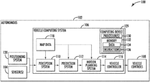
- FIG. 1 depicts a block diagram of an example system 100 for controlling the navigation of an autonomous vehicle 102 according to example embodiments of the present disclosure.
- the autonomous vehicle 102 is capable of sensing its environment and navigating with little to no human input.
- the autonomous vehicle 102 can be a ground-based autonomous vehicle (e.g., car, truck, bus, etc.), an air-based autonomous vehicle (e.g., airplane, drone, helicopter, or other aircraft), or other types of vehicles (e.g., watercraft).
- the autonomous vehicle 102 can be configured to operate in one or more modes, for example, a fully autonomous operational mode and/or a semi-autonomous operational mode.
- a fully autonomous (e.g., self-driving) operational mode can be one in which the autonomous vehicle can provide driving and navigational operation with minimal and/or no interaction from a human driver present in the vehicle.
- a semi-autonomous (e.g., driver-assisted) operational mode can be one in which the autonomous vehicle operates with some interaction from a human driver present in the vehicle.
- the autonomous vehicle 102 can include one or more sensors 104 , a vehicle computing system 106 , and one or more vehicle controls 108 .
- the vehicle computing system 106 can assist in controlling the autonomous vehicle 102 .
- the vehicle computing system 106 can receive sensor data from the one or more sensors 104 , attempt to comprehend the surrounding environment by performing various processing techniques on data collected by the sensors 104 , and generate an appropriate motion path through such surrounding environment.
- the vehicle computing system 106 can control the one or more vehicle controls 108 to operate the autonomous vehicle 102 according to the motion path.
- the vehicle computing system 106 can include one or more processors 130 and at least one memory 132 .
- the one or more processors 130 can be any suitable processing device (e.g., a processor core, a microprocessor, an ASIC, a FPGA, a controller, a microcontroller, etc.) and can be one processor or a plurality of processors that are operatively connected.
- the memory 132 can include one or more non-transitory computer-readable storage mediums, such as RAM, ROM, EEPROM, EPROM, flash memory devices, magnetic disks, etc., and combinations thereof.
- the memory 132 can store data 134 and instructions 136 which are executed by the processor 130 to cause vehicle computing system 106 to perform operations.
- the one or more processors 130 and at least one memory 132 may be comprised in one or more computing devices, such as computing device(s) 129 , within the vehicle computing system 106 .
- vehicle computing system 106 can further include a positioning system 120 .
- the positioning system 120 can determine a current position of the autonomous vehicle 102 .
- the positioning system 120 can be any device or circuitry for analyzing the position of the autonomous vehicle 102 .
- the positioning system 120 can determine position by using one or more of inertial sensors, a satellite positioning system, based on IP address, by using triangulation and/or proximity to network access points or other network components (e.g., cellular towers, WiFi access points, etc.) and/or other suitable techniques for determining position.
- the position of the autonomous vehicle 102 can be used by various systems of the vehicle computing system 106 .
- the vehicle computing system 106 can include a perception system 110 , a prediction system 112 , and a motion planning system 114 that cooperate to perceive the surrounding environment of the autonomous vehicle 102 and determine a motion plan for controlling the motion of the autonomous vehicle 102 accordingly.
- the perception system 110 can receive sensor data from the one or more sensors 104 that are coupled to or otherwise included within the autonomous vehicle 102 .
- the one or more sensors 104 can include a Light Detection and Ranging (LIDAR) system, a Radio Detection and Ranging (RADAR) system, one or more cameras (e.g., visible spectrum cameras, infrared cameras, etc.), and/or other sensors.
- LIDAR Light Detection and Ranging
- RADAR Radio Detection and Ranging
- the sensor data can include information that describes the location of objects within the surrounding environment of the autonomous vehicle 102 .
- the sensor data can include the location (e.g., in three-dimensional space relative to the LIDAR system) of a number of points that correspond to objects that have reflected a ranging laser.
- LIDAR system can measure distances by measuring the Time of Flight (TOF) that it takes a short laser pulse to travel from the sensor to an object and back, calculating the distance from the known speed of light.
- TOF Time of Flight
- the sensor data can include the location (e.g., in three-dimensional space relative to RADAR system) of a number of points that correspond to objects that have reflected a ranging radio wave.
- radio waves (pulsed or continuous) transmitted by the RADAR system can reflect off an object and return to a receiver of the RADAR system, giving information about the object's location and speed.
- RADAR system can provide useful information about the current speed of an object.
- various processing techniques e.g., range imaging techniques such as, for example, structure from motion, structured light, stereo triangulation, and/or other techniques
- range imaging techniques such as, for example, structure from motion, structured light, stereo triangulation, and/or other techniques
- Other sensor systems can identify the location of points that correspond to objects as well.
- the one or more sensors 104 can be used to collect sensor data that includes information that describes the location (e.g., in three-dimensional space relative to the autonomous vehicle 102 ) of points that correspond to objects within the surrounding environment of the autonomous vehicle 102 .
- the perception system 110 can retrieve or otherwise obtain map data 118 that provides detailed information about the surrounding environment of the autonomous vehicle 102 .
- the map data 118 can provide information regarding: the identity and location of different travelways (e.g., roadways), road segments, buildings, or other items or objects (e.g., lampposts, crosswalks, curbing, etc.); the location and directions of traffic lanes (e.g., the location and direction of a parking lane, a turning lane, a bicycle lane, or other lanes within a particular roadway or other travelway); traffic control data (e.g., the location and instructions of signage, traffic lights, or other traffic control devices); and/or any other map data that provides information that assists the vehicle computing system 106 in comprehending and perceiving its surrounding environment and its relationship thereto.
- travelways e.g., roadways
- road segments e.g., buildings, or other items or objects (e.g., lampposts, crosswalks, curbing, etc.)
- traffic lanes
- the perception system 110 can identify one or more objects that are proximate to the autonomous vehicle 102 based on sensor data received from the one or more sensors 104 and/or the map data 118 .
- the perception system 110 can determine, for each object, state data that describes a current state of such object.
- the state data for each object can describe an estimate of the object's: current location (also referred to as position); current speed; current heading (also referred to together as velocity); current acceleration; current orientation; size/footprint (e.g., as represented by a bounding shape such as a bounding polygon or polyhedron); class (e.g., vehicle versus pedestrian versus bicycle versus other); yaw rate; and/or other state information.
- the perception system 110 can determine state data for each object over a number of iterations. In particular, the perception system 110 can update the state data for each object at each iteration. Thus, the perception system 110 can detect and track objects (e.g., vehicles, pedestrians, bicycles, and the like) that are proximate to the autonomous vehicle 102 over time.
- objects e.g., vehicles, pedestrians, bicycles, and the like
- the prediction system 112 can receive the state data from the perception system 110 and predict one or more future locations for each object based on such state data. For example, the prediction system 112 can predict where each object will be located within the next 5 seconds, 10 seconds, 20 seconds, etc. As one example, an object can be predicted to adhere to its current trajectory according to its current speed. As another example, other, more sophisticated prediction techniques or modeling can be used.
- the motion planning system 114 can determine a motion plan for the autonomous vehicle 102 based at least in part on the predicted one or more future locations for the object provided by the prediction system 112 and/or the state data for the object provided by the perception system 110 . Stated differently, given information about the current locations of objects and/or predicted future locations of proximate objects, the motion planning system 114 can determine a motion plan for the autonomous vehicle 102 that best navigates the autonomous vehicle 102 relative to the objects at such locations.
- the motion planning system 114 can determine a cost function for each of one or more candidate motion plans for the autonomous vehicle 102 based at least in part on the current locations and/or predicted future locations of the objects.
- the cost function can describe a cost (e.g., over time) of adhering to a particular candidate motion plan.
- the cost described by a cost function can increase when the autonomous vehicle 102 approaches a possible impact with another object and/or deviates from a preferred pathway (e.g., a preapproved pathway).
- the motion planning system 114 can determine a cost of adhering to a particular candidate pathway.
- the motion planning system 114 can select or determine a motion plan for the autonomous vehicle 102 based at least in part on the cost function(s). For example, the candidate motion plan that minimizes the cost function can be selected or otherwise determined.
- the motion planning system 114 can provide the selected motion plan to a vehicle controller 116 .
- the vehicle controller 116 can generate one or more commands, based at least in part on the motion plan, which can be provided to one or more vehicle interfaces.
- the one or more commands from the vehicle controller 116 can provide for operating one or more vehicle controls 108 (e.g., actuators or other devices that control acceleration, throttle, steering, braking, etc.) to execute the selected motion plan.
- vehicle controls 108 e.g., actuators or other devices that control acceleration, throttle, steering, braking, etc.
- Each of the perception system 110 , the prediction system 112 , the motion planning system 114 , and the vehicle controller 116 can include computer logic utilized to provide desired functionality.
- each of the perception system 110 , the prediction system 112 , the motion planning system 114 , and the vehicle controller 116 can be implemented in hardware, firmware, and/or software controlling a general purpose processor.
- each of the perception system 110 , the prediction system 112 , the motion planning system 114 , and the vehicle controller 116 includes program files stored on a storage device, loaded into a memory, and executed by one or more processors.
- each of the perception system 110 , the prediction system 112 , the motion planning system 114 , and the vehicle controller 116 includes one or more sets of computer-executable instructions that are stored in a tangible computer-readable storage medium such as RAM hard disk or optical or magnetic media.
- FIG. 2 depicts a block diagram of a first example vehicle controller and safety monitor system 200 according to example embodiments of the present disclosure.
- a computing system such as vehicle computing system 202
- vehicle computing system 202 can include an autonomy system 204 (for example, as described in regard to the vehicle computing system 106 of FIG. 1 ) and a safety monitor system 206 .
- the safety monitor system 206 can reside between the autonomy system 204 and one or more vehicle controls, such as vehicle control 208 .
- the vehicle computing system 202 and in particular, the safety monitor system 206 , can communicate with the one or more vehicle controls 208 via one or more CAN interfaces.
- the safety monitor system 206 can monitor the outputs of the autonomy system 204 , such as vehicle command data from a vehicle controller comprised within the autonomy system 204 , and provide the outputs (e.g., vehicle command data, etc.) to the vehicle control(s) 208 via the CAN interface(s).
- the safety monitor system 206 can detect one or more error conditions and/or failure modes of the autonomy system 204 and in particular, error conditions and/or failure modes of the vehicle controller.
- the safety monitor system 206 can monitor whether signals are being received from the vehicle controller and determine whether there is a potential error condition and/or failure mode that may impact autonomous vehicle operation.
- the safety monitor system 206 can determine the amount of time that has passed since a signal from the autonomy system 204 (e.g., the vehicle controller, etc.) has been updated. If the amount of time is greater than a threshold amount of time, the safety monitor system 206 can determine that an error/failure has occurred and can generate one or more signals to provide for an appropriate response.
- the safety monitor system 206 can initiate one or more appropriate responses and/or maneuvers, such as generating one or more signals/commands to execute a safe stop of the vehicle, alert a driver to the failure, disengage the autonomous operation of the vehicle, and/or the like, for example.
- the safety monitor system 206 can maintain a history of previous signals and/or command messages received from the autonomy system 204 (e.g., the vehicle controller, etc.). The safety monitor system 206 can generate a timestamp for each message as it is received. The safety monitor system 206 can determine the amount of time that has passed since the last message was received on each successive cycle (e.g., current time minus timestamp of last message). Alternatively, the safety monitor system 206 can use a timer to measure the time from the receipt of the last message. The safety monitor system 206 can determine if the amount of time that has passed has reached or exceeded a threshold amount of time, and in response, determine that an error and/or failure has occurred. Upon determining that a failure and/or error has occurred, the safety monitor system 206 can generate one or more commands and/or signals to initiate an appropriate response.
- the autonomy system 204 e.g., the vehicle controller, etc.
- the safety monitor 206 can obtain vehicle data, such as vehicle motion data and/or vehicle state data for example, from the vehicle control(s) 208 via the CAN interface(s).
- vehicle data such as vehicle motion data and/or vehicle state data for example
- the safety monitor system 206 can provide the vehicle data to the autonomy system 204 , for example to provide for controlling operation of an autonomous vehicle.
- FIG. 3 depicts a block diagram of another example vehicle controller and safety monitor system 300 according to example embodiments of the present disclosure.
- a vehicle controller and safety monitor system 300 can include a computing system, such as vehicle computing system 302 and one or more vehicle controls 308 .
- the vehicle computing system 302 can include an autonomy system 304 (for example, as described in regard to the vehicle computing system 106 of FIG. 1 ) and a safety monitor system 306 .
- the safety monitor system 306 can reside between the autonomy system 304 and the vehicle control(s) 308 .
- the vehicle computing system 302 and in particular, the safety monitor system 306 , can communicate with the vehicle control(s) 308 via one or more CAN interfaces.
- the safety monitor system 306 can monitor the outputs of the autonomy system 304 , such as vehicle command data from a vehicle controller comprised within the autonomy system 304 , and provide the outputs (e.g., vehicle command data, etc.) to the vehicle control(s) 308 via the CAN interface(s).
- the safety monitor system 206 can detect one or more error conditions and/or failure modes of the autonomy system 204 and in particular, error conditions and/or failure modes of the vehicle controller.
- the autonomy system 304 can also provide a readiness signal to the safety monitor system 306 , such that the safety monitor system 306 can also monitor whether an autonomous vehicle is ready to engage autonomous operation.
- the safety monitor system 306 can determine that the vehicle controller is providing signals and/or command messages and that the vehicle is ready to engage before allowing a driver to engage the autonomous operation.
- the safety monitor 306 can obtain vehicle data, such as vehicle motion data and/or vehicle state data for example, from the vehicle control(s) 3208 via the CAN interface(s).
- vehicle data such as vehicle motion data and/or vehicle state data for example
- the safety monitor system 306 can provide the vehicle data to the autonomy system 304 , for example to provide for controlling operation of an autonomous vehicle.
- FIG. 4 depicts a block diagram of an example controller safety monitor system 402 according to example embodiments of the present disclosure.
- a vehicle controller safety monitor system 402 can include a vehicle controller monitor 404 , a message reader 406 , and a message writer 408 .
- the safety monitor system 402 can obtain vehicle command data from an autonomy system (e.g., as described in regard to FIG. 1 ).
- the vehicle command data can be provided to the vehicle controller monitor 404 and the message writer 408 .
- the vehicle controller monitor 404 can generate a timestamp for the vehicle command data as it is received and can maintain a history of the vehicle command data received from the autonomy system (e.g., the vehicle controller, etc.).
- the vehicle controller monitor 404 can determine the amount of time that has passed since the last command was received on each successive cycle (e.g., current time minus timestamp of last command). Alternatively, the vehicle controller monitor 404 can use a timer to measure the time from the receipt of the last command.
- the vehicle controller monitor 404 can determine if the amount of time that has passed has reached or exceeded a threshold amount of time. As long as the elapsed time has not reached or exceeded a threshold amount of time, the vehicle controller monitor 404 can provide a readiness signal to the message writer 408 . Upon receiving readiness signal, the message writer 408 can provide the vehicle command data to one or more vehicle controls, for example via one or more CAN interfaces. If the amount of time that has elapsed has reached or exceeded a threshold amount of time, the vehicle controller monitor 404 can determine that an error and/or failure has occurred and can generate one or more commands and/or signals to initiate an appropriate response.
- the message reader 406 can obtain vehicle data, such as vehicle motion data and/or vehicle state data, from one or more vehicle controls, for example via one or more CAN interfaces.
- vehicle data such as vehicle motion data and/or vehicle state data
- the message reader 406 can provide the vehicle motion and vehicle state data to the autonomy system, for example, to provide for controlling operation of an autonomous vehicle.
- the message reader can also provide the vehicle state data to the vehicle controller monitor 404 .
- FIG. 5 depicts a block diagram of an example controller safety monitor system 502 according to example embodiments of the present disclosure.
- a vehicle controller safety monitor system 502 can include a vehicle controller monitor 504 , a message reader 506 , and a message writer 508 .
- the safety monitor system 502 can obtain vehicle command data from an autonomy system (e.g., as described in regard to FIG. 1 ).
- the vehicle command data can be provided to the vehicle controller monitor 504 and the message writer 508 .
- the vehicle controller monitor 504 can also obtain a controller readiness signal from the autonomy system (e.g., a vehicle controller, etc.) for use in determining whether autonomous operation can be engaged or maintained.
- the vehicle controller monitor 504 can generate a timestamp for the vehicle command data as it is received and can maintain a history of the vehicle command data received from the autonomy system (e.g., the vehicle controller, etc.). The vehicle controller monitor 504 can determine the amount of time that has passed since the last command was received on each successive cycle (e.g., current time minus timestamp of last command). Alternatively, the vehicle controller monitor 504 can use a timer to measure the time from the receipt of the last command. The vehicle controller monitor 504 can determine if the amount of time that has passed has reached or exceeded a threshold amount of time.
- the autonomy system e.g., the vehicle controller, etc.
- the vehicle controller monitor 504 can determine the amount of time that has passed since the last command was received on each successive cycle (e.g., current time minus timestamp of last command). Alternatively, the vehicle controller monitor 504 can use a timer to measure the time from the receipt of the last command. The vehicle controller monitor 504 can determine if the amount of time that has passed has
- the vehicle controller monitor 504 can provide a readiness signal to the message writer 508 .
- the message writer 508 can provide the vehicle command data to one or more vehicle controls, for example via one or more CAN interfaces. If the amount of time that has elapsed has reached or exceeded a threshold amount of time and/or the controller readiness signal has not been received, the vehicle controller monitor 504 can determine that an error and/or failure has occurred and can generate one or more commands and/or signals to initiate an appropriate response.
- the message reader 506 can obtain vehicle data, such as vehicle motion data and/or vehicle state data, from one or more vehicle controls, for example via one or more CAN interfaces.
- vehicle data such as vehicle motion data and/or vehicle state data
- the message reader 506 can provide the vehicle motion and vehicle state data to the autonomy system, for example, to provide for controlling operation of an autonomous vehicle.
- the message reader can also provide the vehicle state data to the vehicle controller monitor 504 .
- FIG. 6 depicts a block diagram of an example autonomy system comprising a task health monitor system 600 according to example embodiments of the present disclosure.
- a computing system 602 can include an autonomy system 604 and a health monitor 606 .
- one or more autonomy subsystems included in autonomy system 604 can be monitored in addition to the vehicle controller.
- the safety monitor system can provide different responses to the error conditions/failure modes depending on the subsystem affected.
- the autonomy system 604 can receive sensor data and/or other data (e.g. map data, positioning system data, vehicle motion data, vehicle state data, and/or the like) and determine commands to provide for autonomous operation of a vehicle.
- the autonomy system 604 can generate vehicle trajectory and pose data to provide for determining vehicle command data.
- the vehicle command data can be provided to a safety monitor system (e.g., as described in regard to FIG. 5 ) which can provide the vehicle command data to one or more vehicle controls.
- One or more subsystems included in the autonomy system 604 can provide readiness signals to the health monitor 606 indicating that the subsystem(s) are functioning properly and that autonomous operation may be engaged and/or maintained (e.g., the subsystem(s) are not in an error/failure state).
- the health monitor 606 can provide a readiness signal to the safety monitor system, for example, as described in regard to FIG. 5 .
- FIG. 7A depicts a flowchart diagram of example operations 700 A for monitoring an autonomous vehicle controller according to example embodiments of the present disclosure.
- One or more portion(s) of the operations 700 A can be implemented by one or more computing devices such as, for example, the vehicle computing system 106 of FIG. 1 , the computing system 902 or 106 of FIG. 9 , or the like.
- one or more portion(s) of the operations 700 A can be implemented as an algorithm on the hardware components of the device(s) described herein (e.g., as in FIGS. 1 and 9 ) to, for example, provide for monitoring a vehicle controller during autonomous vehicle operation.
- one or more computing devices included within a computing system can obtain vehicle command data (e.g., command messages) from a vehicle controller (e.g., vehicle controller 116 of FIG. 1 , for example).
- vehicle command data e.g., command messages
- the command data can be monitored to determine whether signals are being received from the vehicle controller and subsequently determine whether there is a potential error condition and/or failure mode that may impact autonomous vehicle operation.
- the computing system can determine whether an error mode exists in regard to the vehicle controller has error mode based on the command message flow. For example, the computing system can determine the amount of time that has passed since a message has been received from the vehicle controller. If the amount of time is greater than a threshold amount of time, the computing can determine that an error/failure has occurred in the vehicle controller.
- the computing system can provide one or more commands to implement an appropriate response to the error. For example, the computing system can initiate one or more appropriate responses and/or maneuvers, such as generating one or more signals/commands to execute a safe stop of the vehicle, alert a driver to the failure, disengage the autonomous operation of the vehicle, and/or the like, for example.
- FIG. 7B depicts a flowchart diagram of example operations 700 B for monitoring an autonomous vehicle controller according to example embodiments of the present disclosure.
- operations 700 B provide example operations in regard to determining an error mode as described in regard to operation 704 of FIG. 7A .
- One or more portion(s) of the operations 700 B can be implemented by one or more computing devices such as, for example, the vehicle computing system 106 of FIG. 1 , the computing system 902 or 106 of FIG. 9 , or the like.
- one or more portion(s) of the operations 700 B can be implemented as an algorithm on the hardware components of the device(s) described herein (e.g., as in FIGS. 1 and 9 ) to, for example, provide for monitoring a vehicle controller during autonomous vehicle operation.
- one or more computing devices included within a computing system can receive a message (e.g., vehicle command data) from a vehicle controller.
- a message e.g., vehicle command data
- the computing system can generate a timestamp for the received message and store the received message along with the timestamp in a command history.
- the computing system can determine a difference amount between the current time and the last message timestamp at each successive cycle.
- the computing system can determine if the difference amount has reached or exceeded a threshold amount of time at each successive cycle. If the difference amount has reached or exceeded a threshold amount of time, the operation continues to 718 . If the difference amount has not reached or exceeded a threshold amount of time, operation returns to 714 for a difference amount to be determined in the next cycle.
- the computing system can determine if a new message has been received from the vehicle controller. If a new message has been received, operation returns to 712 , and the new message can be timestamped and stored to the command history. If a new message has not been received from the vehicle controller, operation continues to 720 .
- the computing system can determine that an error has occurred in regard to the vehicle controller and can report the error for use in determining an appropriate response, as described in regard to operation 706 of FIG. 7A .
- FIG. 8 depicts a flowchart diagram of example operations 800 for monitoring an autonomous vehicle controller and/or other autonomy subsystem(s) according to example embodiments of the present disclosure.
- One or more portion(s) of the operations 800 can be implemented by one or more computing devices such as, for example, the vehicle computing system 106 of FIG. 1 , the computing system 902 or 106 of FIG. 9 , or the like.
- one or more portion(s) of the operations 800 can be implemented as an algorithm on the hardware components of the device(s) described herein (e.g., as in FIGS. 1 and 9 ) to, for example, provide for monitoring a vehicle controller or other autonomy subsystem during autonomous vehicle operation.
- one or more computing devices included within a computing system can obtain vehicle command data (e.g., command messages) from a vehicle controller (e.g., vehicle controller 116 of FIG. 1 , for example).
- vehicle command data e.g., command messages
- the command data can be monitored to determine whether signals are being received from the vehicle controller and subsequently determine whether there is a potential error condition and/or failure mode that may impact autonomous vehicle operation.
- the computing system can determine whether an error mode exists in regard to the vehicle controller has error mode based on the command message flow. For example, the computing system can determine the amount of time that has passed since a message has been received from the vehicle controller. If the amount of time is greater than a threshold amount of time, the computing can determine that an error/failure has occurred in the vehicle controller.
- the computing system can additionally obtain an error/failure status from one or more other autonomy subsystems.
- one or more autonomy subsystems can be monitored in addition to the vehicle controller.
- the computing system can provide different responses to the error modes/failure states depending on the subsystem affected.
- each of the subsystems such as sensors, perception, prediction, motion planning, and/or the like can have their own error modes/failure states.
- each subsystem can have its own monitoring metrics which can be understood by the computing system.
- Each subsystem can monitor for its own failure modes (e.g., edge cases) and report its failure mode to the computing system in a common format.
- the computing system can determine if the vehicle controller is in an error/failure state (from operation 804 ) and/or if one or more subsystems is in an error/failure state (from operation 806 ). If the vehicle controller and/or one or more other subsystems are in an error/failure state, operation continues to 810 . If the vehicle controller and other subsystem(s) are not in an error/failure state operation returns to 802 / 806 to continuing monitoring the vehicle controller and/or other subsystem(s).
- the computing system can provide one or more commands to implement an appropriate response to the error. For example, the computing system can initiate one or more appropriate responses and/or maneuvers, such as generating one or more signals/commands to execute a safe stop of the vehicle, alert a driver to the failure, disengage the autonomous operation of the vehicle, and/or the like, for example.
- the computing system can initiate one or more appropriate responses and/or maneuvers, such as generating one or more signals/commands to execute a safe stop of the vehicle, alert a driver to the failure, disengage the autonomous operation of the vehicle, and/or the like, for example.
- FIGS. 7A, 7B, and 8 depict steps performed in a particular order for purposes of illustration and discussion, the methods of the present disclosure are not limited to the particularly illustrated order or arrangement.
- the various steps of the methods 700 A, 700 B, and 800 can be omitted, rearranged, combined, and/or adapted in various ways without deviating from the scope of the present disclosure.
- FIG. 9 depicts a block diagram of an example computing system 900 according to example embodiments of the present disclosure.
- the example computing system 900 illustrated in FIG. 9 is provided as an example only.
- the components, systems, connections, and/or other aspects illustrated in FIG. 9 are optional and are provided as examples of what is possible, but not required, to implement the present disclosure.
- the example computing system 900 can include the vehicle computing system 106 of the autonomous vehicle 102 and a computing system 902 (e.g., an operations computing system), including one or more computing device(s) 903 , that is remote from the autonomous vehicle 102 .
- the vehicle computing system 106 of the autonomous vehicle 102 and the computing system 902 can be communicatively coupled to one another over one or more networks 920 .
- the computing system 902 can, for example, be associated with a central operations system and/or an entity associated with the autonomous vehicle 102 such as, for example, a vehicle owner, vehicle manager, fleet operator, service provider, etc.
- the computing device(s) 903 of the computing system 902 can include processor(s) 904 and a least one memory 906 .
- the one or more processors 904 can be any suitable processing device (e.g., a processor core, a microprocessor, an ASIC, a FPGA, a controller, a microcontroller, etc.) and can be one processor or a plurality of processors that are operatively connected.
- the memory 906 can include one or more non-transitory computer-readable storage media, such as RAM, ROM, EEPROM, EPROM, one or more memory devices, flash memory devices, etc., and combinations thereof.
- the memory 906 can store information that can be accessed by the one or more processors 904 .
- the memory 906 e.g., one or more non-transitory computer-readable storage mediums, memory devices
- the memory 906 can include computer-readable instructions 908 can be executed by the one or more processors 904 .
- the instructions 908 can be software written in any suitable programming language or can be implemented in hardware. Additionally, or alternatively, the instructions 908 can be executed in logically and/or virtually separate threads on processor(s) 904 .
- the memory 906 can store instructions 908 that when executed by the one or more processors 904 cause the one or more processors 904 to perform operations such as any of the operations and functions of the computing device(s) 903 or for which the computing device(s) 903 are configured, as described herein including, for example, operations of FIGS. 7A, 7B , and/or 8 .
- the memory 906 can store data 910 that can be obtained, received, accessed, written, manipulated, created, and/or stored.
- the data 910 can include, for instance, sensor data, map data, service request data (e.g., trip and/or user data), operational data, etc., as described herein.
- the computing device(s) 903 can obtain data from one or more memory device(s) that are remote from the computing system 902 .
- the computing device(s) 903 can also include one or more communication interfaces 912 used to communicate with one or more other system(s) associated with the computing system 902 and/or another computing device that is remote from the computing system 902 , such as the vehicle computing system 106 of the autonomous vehicle 102 , for example.
- the communication interface 912 can include any circuits, components, software, etc. for communicating with one or more networks (e.g., 920 ).
- the communication interface 912 can include for example, one or more of a communications controller, receiver, transceiver, transmitter, port, conductors, software, and/or hardware for communicating data.
- the network(s) 920 can be any type of network or combination of networks that allows for communication between devices.
- the network(s) can include one or more of a local area network, wide area network, the Internet, secure network, cellular network, mesh network, peer-to-peer communication link, and/or some combination thereof, and can include any number of wired or wireless links.
- Communication over the network(s) 920 can be accomplished, for instance, via a communication interface using any type of protocol, protection scheme, encoding, format, packaging, etc.
- the vehicle computing system 106 of the autonomous vehicle can include one or more computing devices, such as described in regard to FIG. 1 .
- the remote computing devices can include components (e.g., processor(s), memory, instructions, data, etc.) similar to that described herein for the computing device(s) 903 , and as described in regard to FIG. 1 .
- the vehicle computing system 106 can be configured to perform one or more operations, as described herein including, for example, operations of FIGS. 7A, 7B , and/or 8 .
- Computing tasks discussed herein as being performed at computing device(s) remote from the autonomous vehicle can instead be performed at the autonomous vehicle (e.g., via the vehicle computing system), or vice versa. Such configurations can be implemented without deviating from the scope of the present disclosure.
- the use of computer-based systems allows for a great variety of possible configurations, combinations, and divisions of tasks and functionality between and among components.
- Computer-implemented operations can be performed on a single component or across multiple components.
- Computer-implements tasks and/or operations can be performed sequentially or in parallel.
- Data and instructions can be stored in a single memory device or across multiple memory devices.
Landscapes
- Engineering & Computer Science (AREA)
- Automation & Control Theory (AREA)
- Theoretical Computer Science (AREA)
- Physics & Mathematics (AREA)
- General Physics & Mathematics (AREA)
- Transportation (AREA)
- Mechanical Engineering (AREA)
- Human Computer Interaction (AREA)
- Quality & Reliability (AREA)
- General Engineering & Computer Science (AREA)
- Aviation & Aerospace Engineering (AREA)
- Remote Sensing (AREA)
- Radar, Positioning & Navigation (AREA)
- Business, Economics & Management (AREA)
- Game Theory and Decision Science (AREA)
- Medical Informatics (AREA)
- Evolutionary Computation (AREA)
- Artificial Intelligence (AREA)
- Health & Medical Sciences (AREA)
- Traffic Control Systems (AREA)
Abstract
Description
Claims (17)
Priority Applications (1)
| Application Number | Priority Date | Filing Date | Title |
|---|---|---|---|
| US15/810,495 US10710602B2 (en) | 2017-10-06 | 2017-11-13 | Systems and methods for a vehicle controller safety monitor |
Applications Claiming Priority (2)
| Application Number | Priority Date | Filing Date | Title |
|---|---|---|---|
| US201762569054P | 2017-10-06 | 2017-10-06 | |
| US15/810,495 US10710602B2 (en) | 2017-10-06 | 2017-11-13 | Systems and methods for a vehicle controller safety monitor |
Publications (2)
| Publication Number | Publication Date |
|---|---|
| US20190106117A1 US20190106117A1 (en) | 2019-04-11 |
| US10710602B2 true US10710602B2 (en) | 2020-07-14 |
Family
ID=65992916
Family Applications (1)
| Application Number | Title | Priority Date | Filing Date |
|---|---|---|---|
| US15/810,495 Active 2038-09-08 US10710602B2 (en) | 2017-10-06 | 2017-11-13 | Systems and methods for a vehicle controller safety monitor |
Country Status (1)
| Country | Link |
|---|---|
| US (1) | US10710602B2 (en) |
Cited By (2)
| Publication number | Priority date | Publication date | Assignee | Title |
|---|---|---|---|---|
| US20210101607A1 (en) * | 2019-10-08 | 2021-04-08 | GM Global Technology Operations LLC | Adaptive Prognostics Systems and Methods for Vehicles |
| US20220266862A1 (en) * | 2021-02-25 | 2022-08-25 | Autonomous Solutions, Inc. | Intelligent urgent stop system for an autonomous vehicle |
Families Citing this family (33)
| Publication number | Priority date | Publication date | Assignee | Title |
|---|---|---|---|---|
| JP7069456B2 (en) | 2017-03-17 | 2022-05-18 | ザ・リージェンツ・オブ・ザ・ユニバーシティ・オブ・ミシガン | Methods and equipment for building useful results to guide multi-policy decision making |
| EP3824404A4 (en) | 2018-07-20 | 2022-04-27 | May Mobility, Inc. | MULTI-PERSPECTIVE SYSTEM AND BEHAVIORAL POLICY SELECTION PROCESS BY AN AUTONOMOUS AGENT |
| US10614709B2 (en) | 2018-07-24 | 2020-04-07 | May Mobility, Inc. | Systems and methods for implementing multimodal safety operations with an autonomous agent |
| US11587366B1 (en) | 2018-11-20 | 2023-02-21 | State Farm Mutual Automobile Insurance Company | Systems and methods for selecting locations to validate automated vehicle data transmission |
| KR20200081530A (en) * | 2018-12-19 | 2020-07-08 | 주식회사 만도 | Safety control system and method of self-driving vehicles |
| US11167751B2 (en) * | 2019-01-18 | 2021-11-09 | Baidu Usa Llc | Fail-operational architecture with functional safety monitors for automated driving system |
| US11402842B2 (en) | 2019-01-18 | 2022-08-02 | Baidu Usa Llc | Method to define safe drivable area for automated driving system |
| US10969470B2 (en) | 2019-02-15 | 2021-04-06 | May Mobility, Inc. | Systems and methods for intelligently calibrating infrastructure devices using onboard sensors of an autonomous agent |
| US11610142B2 (en) * | 2019-05-28 | 2023-03-21 | Ati Technologies Ulc | Safety monitor for image misclassification |
| US11613253B2 (en) * | 2019-05-29 | 2023-03-28 | Baidu Usa Llc | Method of monitoring localization functions in an autonomous driving vehicle |
| US11106200B2 (en) * | 2019-06-27 | 2021-08-31 | Baidu Usa Llc | Safety mechanism for joystick control for controlling an unmanned vehicle |
| US11456890B2 (en) * | 2019-07-16 | 2022-09-27 | Baidu Usa Llc | Open and safe monitoring system for autonomous driving platform |
| US12135606B2 (en) * | 2019-12-11 | 2024-11-05 | Samsung Electronics Co., Ltd. | Electronic apparatus that monitors a safety function and a controlling method thereof |
| US11254323B2 (en) * | 2020-03-04 | 2022-02-22 | Zoox, Inc. | Localization error monitoring |
| US11440567B2 (en) * | 2020-03-06 | 2022-09-13 | Baidu Usa Llc | System to handle communication delays between an autonomous driving system and vehicle |
| US11760381B1 (en) * | 2020-03-24 | 2023-09-19 | Gm Cruise Holdings Llc | Contextually-aware dynamic safety envelope for autonomous vehicles |
| WO2021232316A1 (en) * | 2020-05-20 | 2021-11-25 | 华为技术有限公司 | Redundant electronic control system and device |
| EP4165476A4 (en) | 2020-07-01 | 2024-07-03 | May Mobility, Inc. | METHOD AND SYSTEM FOR DYNAMIC CURATING OF AUTONOMOUS VEHICLE POLICIES |
| US20220048539A1 (en) * | 2020-08-12 | 2022-02-17 | Autonomous Solutions, Inc. | Autonomous safety rider |
| US11396302B2 (en) | 2020-12-14 | 2022-07-26 | May Mobility, Inc. | Autonomous vehicle safety platform system and method |
| EP4264181A4 (en) | 2020-12-17 | 2024-10-30 | May Mobility, Inc. | METHOD AND SYSTEM FOR DYNAMIC UPDATING OF AN ENVIRONMENT REPRESENTATION OF AN AUTONOMOUS AGENT |
| US20220197236A1 (en) * | 2020-12-18 | 2022-06-23 | Rockwell Collins, Inc. | Hierarchical high integrity automation system |
| CN112550281B (en) * | 2020-12-29 | 2022-05-13 | 广州小鹏自动驾驶科技有限公司 | Automatic parking control method and device |
| EP4314708A4 (en) | 2021-04-02 | 2024-12-25 | May Mobility, Inc. | Method and system for operating an autonomous agent with incomplete environmental information |
| JP7788110B2 (en) | 2021-06-02 | 2025-12-18 | メイ モビリティー,インコーポレイテッド | Method and system for remote assistance of autonomous agents |
| US12012123B2 (en) | 2021-12-01 | 2024-06-18 | May Mobility, Inc. | Method and system for impact-based operation of an autonomous agent |
| US12296849B2 (en) | 2021-12-02 | 2025-05-13 | May Mobility, Inc. | Method and system for feasibility-based operation of an autonomous agent |
| JP7793397B2 (en) * | 2022-01-31 | 2026-01-05 | 株式会社デンソーテン | Control device and control method |
| US11814072B2 (en) | 2022-02-14 | 2023-11-14 | May Mobility, Inc. | Method and system for conditional operation of an autonomous agent |
| KR20230136794A (en) * | 2022-03-17 | 2023-09-27 | 현대자동차주식회사 | Apparatus and method for controlling autonomous driving vehicle |
| US12027053B1 (en) | 2022-12-13 | 2024-07-02 | May Mobility, Inc. | Method and system for assessing and mitigating risks encounterable by an autonomous vehicle |
| US20250036507A1 (en) * | 2023-07-26 | 2025-01-30 | Nvidia Corporation | Modifying operations of systems based on error detection |
| DE102024100203A1 (en) * | 2024-01-04 | 2025-07-10 | Valeo Schalter Und Sensoren Gmbh | Computer-implemented method for monitoring a function of a vehicle |
Citations (15)
| Publication number | Priority date | Publication date | Assignee | Title |
|---|---|---|---|---|
| US20140244096A1 (en) * | 2013-02-27 | 2014-08-28 | Electronics And Telecommunications Research Institute | Apparatus and method for cooperative autonomous driving between vehicle and driver |
| US20140335823A1 (en) * | 2010-04-22 | 2014-11-13 | Zipit Wireless, Inc. | System And Method For Administration And Operation Of One Or More Mobile Electronic Communications Devices |
| US20150158499A1 (en) * | 2013-12-05 | 2015-06-11 | Magna Electronics Inc. | Vehicle monitoring system |
| US20160036814A1 (en) * | 2014-07-30 | 2016-02-04 | Master Lock Company Llc | Wireless firmware updates |
| US20160167653A1 (en) * | 2014-12-15 | 2016-06-16 | Polaris Industries, Inc. | Autonomous ready vehicle |
| US20170139411A1 (en) * | 2015-11-16 | 2017-05-18 | Polysync Technologies, Inc. | Autonomous Vehicle Platform and Safety Architecture |
| US20170228279A1 (en) * | 2014-08-04 | 2017-08-10 | Yogitech S.P.A. | Method of executing programs in an electronic system for applications with functional safety comprising a plurality of processors, corresponding system and computer program product |
| US20180009446A1 (en) * | 2016-07-07 | 2018-01-11 | NextEv USA, Inc. | System and method for associating user and vehicle information for communication to a third party |
| US20180061212A1 (en) * | 2016-08-26 | 2018-03-01 | Trane International Inc. | System and method to assist building automation system end user based on alarm parameters |
| US20180103036A1 (en) * | 2016-10-11 | 2018-04-12 | Whitefox Defense Technologies, Inc. | Systems and methods for cyber-physical vehicle management, detection and control |
| US20180241199A1 (en) * | 2017-02-22 | 2018-08-23 | General Electric Company | Power distribution systems and methods of performing zone selective interlocking in power distribution systems with a communication network |
| US20180349259A1 (en) * | 2015-10-13 | 2018-12-06 | Intel Corporation | Method for executing programs in an electronic system for applications with functional safety comprising a plurality of processors, corresponding system and computer program product |
| US20190004854A1 (en) * | 2017-07-03 | 2019-01-03 | Baidu Usa Llc | Centralized scheduling system using event loop for operating autonomous driving vehicles |
| US20190066399A1 (en) * | 2017-08-28 | 2019-02-28 | GM Global Technology Operations LLC | Controller architecture for monitoring health of an autonomous vehicle |
| US10326793B2 (en) * | 2015-06-10 | 2019-06-18 | RunSafe Security, Inc. | System and method for guarding a controller area network |
-
2017
- 2017-11-13 US US15/810,495 patent/US10710602B2/en active Active
Patent Citations (15)
| Publication number | Priority date | Publication date | Assignee | Title |
|---|---|---|---|---|
| US20140335823A1 (en) * | 2010-04-22 | 2014-11-13 | Zipit Wireless, Inc. | System And Method For Administration And Operation Of One Or More Mobile Electronic Communications Devices |
| US20140244096A1 (en) * | 2013-02-27 | 2014-08-28 | Electronics And Telecommunications Research Institute | Apparatus and method for cooperative autonomous driving between vehicle and driver |
| US20150158499A1 (en) * | 2013-12-05 | 2015-06-11 | Magna Electronics Inc. | Vehicle monitoring system |
| US20160036814A1 (en) * | 2014-07-30 | 2016-02-04 | Master Lock Company Llc | Wireless firmware updates |
| US20170228279A1 (en) * | 2014-08-04 | 2017-08-10 | Yogitech S.P.A. | Method of executing programs in an electronic system for applications with functional safety comprising a plurality of processors, corresponding system and computer program product |
| US20160167653A1 (en) * | 2014-12-15 | 2016-06-16 | Polaris Industries, Inc. | Autonomous ready vehicle |
| US10326793B2 (en) * | 2015-06-10 | 2019-06-18 | RunSafe Security, Inc. | System and method for guarding a controller area network |
| US20180349259A1 (en) * | 2015-10-13 | 2018-12-06 | Intel Corporation | Method for executing programs in an electronic system for applications with functional safety comprising a plurality of processors, corresponding system and computer program product |
| US20170139411A1 (en) * | 2015-11-16 | 2017-05-18 | Polysync Technologies, Inc. | Autonomous Vehicle Platform and Safety Architecture |
| US20180009446A1 (en) * | 2016-07-07 | 2018-01-11 | NextEv USA, Inc. | System and method for associating user and vehicle information for communication to a third party |
| US20180061212A1 (en) * | 2016-08-26 | 2018-03-01 | Trane International Inc. | System and method to assist building automation system end user based on alarm parameters |
| US20180103036A1 (en) * | 2016-10-11 | 2018-04-12 | Whitefox Defense Technologies, Inc. | Systems and methods for cyber-physical vehicle management, detection and control |
| US20180241199A1 (en) * | 2017-02-22 | 2018-08-23 | General Electric Company | Power distribution systems and methods of performing zone selective interlocking in power distribution systems with a communication network |
| US20190004854A1 (en) * | 2017-07-03 | 2019-01-03 | Baidu Usa Llc | Centralized scheduling system using event loop for operating autonomous driving vehicles |
| US20190066399A1 (en) * | 2017-08-28 | 2019-02-28 | GM Global Technology Operations LLC | Controller architecture for monitoring health of an autonomous vehicle |
Cited By (3)
| Publication number | Priority date | Publication date | Assignee | Title |
|---|---|---|---|---|
| US20210101607A1 (en) * | 2019-10-08 | 2021-04-08 | GM Global Technology Operations LLC | Adaptive Prognostics Systems and Methods for Vehicles |
| US11904875B2 (en) * | 2019-10-08 | 2024-02-20 | GM Global Technology Operations LLC | Adaptive prognostics systems and methods for vehicles |
| US20220266862A1 (en) * | 2021-02-25 | 2022-08-25 | Autonomous Solutions, Inc. | Intelligent urgent stop system for an autonomous vehicle |
Also Published As
| Publication number | Publication date |
|---|---|
| US20190106117A1 (en) | 2019-04-11 |
Similar Documents
| Publication | Publication Date | Title |
|---|---|---|
| US10710602B2 (en) | Systems and methods for a vehicle controller safety monitor | |
| US20230418307A1 (en) | Autonomous Vehicle Collision Mitigation Systems and Methods | |
| US11693409B2 (en) | Systems and methods for a scenario tagger for autonomous vehicles | |
| US10618519B2 (en) | Systems and methods for autonomous vehicle lane change control | |
| US11724708B2 (en) | Fail-safe handling system for autonomous driving vehicle | |
| US10768628B2 (en) | Systems and methods for object detection at various ranges using multiple range imagery | |
| US10496099B2 (en) | Systems and methods for speed limit context awareness | |
| US12214724B2 (en) | Systems and methods for deploying warning devices from an autonomous vehicle | |
| US20190061765A1 (en) | Systems and Methods for Performing Lane Changes Around Obstacles | |
| US20190039609A1 (en) | Multi-Model Switching On a Collision Mitigation System | |
| US20190110174A1 (en) | Systems and Methods for a Vehicle Application Programming Interface | |
| US11531349B2 (en) | Corner case detection and collection for a path planning system | |
| EP3914880B1 (en) | Vehicle routing with local and general routes | |
| US11592810B2 (en) | Systems and methods for injecting faults into an autonomy system | |
| US11260875B2 (en) | Systems and methods for road surface dependent motion planning | |
| CN114212108A (en) | Automatic driving method, device, vehicle, storage medium and product | |
| KR102806524B1 (en) | Method for predicting and determining abnormal state of autonomous driving vehicle and apparatus and system therefor | |
| US12386773B2 (en) | Peripheral component interconnect express device reset for autonomous driving systems | |
| US20250284287A1 (en) | Method for modelling a navigation environment of a motor vehicle | |
| KR20230152901A (en) | Method for recognizing and preventing accident in tele-operated driving system and apparatus and system therefor | |
| CN118170570A (en) | Method and system for detecting message delays and failures within a computing system | |
| CN118062050A (en) | Mutual monitoring of high performance computing (HPC) systems for controlling vehicle operations |
Legal Events
| Date | Code | Title | Description |
|---|---|---|---|
| FEPP | Fee payment procedure |
Free format text: ENTITY STATUS SET TO UNDISCOUNTED (ORIGINAL EVENT CODE: BIG.); ENTITY STATUS OF PATENT OWNER: LARGE ENTITY |
|
| AS | Assignment |
Owner name: UBER TECHNOLOGIES, INC, CALIFORNIA Free format text: ASSIGNMENT OF ASSIGNORS INTEREST;ASSIGNOR:GOLDBERG, JOSHUA DAVID;REEL/FRAME:044407/0944 Effective date: 20171209 |
|
| STPP | Information on status: patent application and granting procedure in general |
Free format text: DOCKETED NEW CASE - READY FOR EXAMINATION |
|
| AS | Assignment |
Owner name: UATC, LLC, CALIFORNIA Free format text: CHANGE OF NAME;ASSIGNOR:UBER TECHNOLOGIES, INC.;REEL/FRAME:050353/0884 Effective date: 20190702 |
|
| STPP | Information on status: patent application and granting procedure in general |
Free format text: NON FINAL ACTION MAILED |
|
| AS | Assignment |
Owner name: UATC, LLC, CALIFORNIA Free format text: CORRECTIVE ASSIGNMENT TO CORRECT THE NATURE OF CONVEYANCE FROM CHANGE OF NAME TO ASSIGNMENT PREVIOUSLY RECORDED ON REEL 050353 FRAME 0884. ASSIGNOR(S) HEREBY CONFIRMS THE CORRECT CONVEYANCE SHOULD BE ASSIGNMENT;ASSIGNOR:UBER TECHNOLOGIES, INC.;REEL/FRAME:051145/0001 Effective date: 20190702 |
|
| STPP | Information on status: patent application and granting procedure in general |
Free format text: RESPONSE TO NON-FINAL OFFICE ACTION ENTERED AND FORWARDED TO EXAMINER |
|
| STPP | Information on status: patent application and granting procedure in general |
Free format text: PUBLICATIONS -- ISSUE FEE PAYMENT VERIFIED |
|
| STCF | Information on status: patent grant |
Free format text: PATENTED CASE |
|
| MAFP | Maintenance fee payment |
Free format text: PAYMENT OF MAINTENANCE FEE, 4TH YEAR, LARGE ENTITY (ORIGINAL EVENT CODE: M1551); ENTITY STATUS OF PATENT OWNER: LARGE ENTITY Year of fee payment: 4 |
|
| AS | Assignment |
Owner name: AURORA OPERATIONS, INC., PENNSYLVANIA Free format text: ASSIGNMENT OF ASSIGNORS INTEREST;ASSIGNOR:UATC, LLC;REEL/FRAME:067733/0001 Effective date: 20240321 Owner name: AURORA OPERATIONS, INC., PENNSYLVANIA Free format text: ASSIGNMENT OF ASSIGNOR'S INTEREST;ASSIGNOR:UATC, LLC;REEL/FRAME:067733/0001 Effective date: 20240321 |