US10702322B2 - Medical insertion apparatus - Google Patents
Medical insertion apparatus Download PDFInfo
- Publication number
- US10702322B2 US10702322B2 US14/467,837 US201414467837A US10702322B2 US 10702322 B2 US10702322 B2 US 10702322B2 US 201414467837 A US201414467837 A US 201414467837A US 10702322 B2 US10702322 B2 US 10702322B2
- Authority
- US
- United States
- Prior art keywords
- screw body
- electrode
- hole
- screw
- insertion apparatus
- Prior art date
- Legal status (The legal status is an assumption and is not a legal conclusion. Google has not performed a legal analysis and makes no representation as to the accuracy of the status listed.)
- Active, expires
Links
Images


Classifications
-
- A—HUMAN NECESSITIES
- A61—MEDICAL OR VETERINARY SCIENCE; HYGIENE
- A61B—DIAGNOSIS; SURGERY; IDENTIFICATION
- A61B17/00—Surgical instruments, devices or methods
- A61B17/56—Surgical instruments or methods for treatment of bones or joints; Devices specially adapted therefor
- A61B17/58—Surgical instruments or methods for treatment of bones or joints; Devices specially adapted therefor for osteosynthesis, e.g. bone plates, screws or setting implements
- A61B17/68—Internal fixation devices, including fasteners and spinal fixators, even if a part thereof projects from the skin
- A61B17/84—Fasteners therefor or fasteners being internal fixation devices
- A61B17/86—Pins or screws or threaded wires; nuts therefor
- A61B17/866—Material or manufacture
-
- A—HUMAN NECESSITIES
- A61—MEDICAL OR VETERINARY SCIENCE; HYGIENE
- A61B—DIAGNOSIS; SURGERY; IDENTIFICATION
- A61B17/00—Surgical instruments, devices or methods
- A61B17/56—Surgical instruments or methods for treatment of bones or joints; Devices specially adapted therefor
- A61B17/58—Surgical instruments or methods for treatment of bones or joints; Devices specially adapted therefor for osteosynthesis, e.g. bone plates, screws or setting implements
- A61B17/68—Internal fixation devices, including fasteners and spinal fixators, even if a part thereof projects from the skin
- A61B17/70—Spinal positioners or stabilisers, e.g. stabilisers comprising fluid filler in an implant
- A61B17/7001—Screws or hooks combined with longitudinal elements which do not contact vertebrae
- A61B17/7032—Screws or hooks with U-shaped head or back through which longitudinal rods pass
-
- A—HUMAN NECESSITIES
- A61—MEDICAL OR VETERINARY SCIENCE; HYGIENE
- A61B—DIAGNOSIS; SURGERY; IDENTIFICATION
- A61B17/00—Surgical instruments, devices or methods
- A61B17/56—Surgical instruments or methods for treatment of bones or joints; Devices specially adapted therefor
- A61B17/58—Surgical instruments or methods for treatment of bones or joints; Devices specially adapted therefor for osteosynthesis, e.g. bone plates, screws or setting implements
- A61B17/68—Internal fixation devices, including fasteners and spinal fixators, even if a part thereof projects from the skin
- A61B17/84—Fasteners therefor or fasteners being internal fixation devices
- A61B17/86—Pins or screws or threaded wires; nuts therefor
- A61B17/8625—Shanks, i.e. parts contacting bone tissue
-
- A—HUMAN NECESSITIES
- A61—MEDICAL OR VETERINARY SCIENCE; HYGIENE
- A61B—DIAGNOSIS; SURGERY; IDENTIFICATION
- A61B17/00—Surgical instruments, devices or methods
- A61B17/56—Surgical instruments or methods for treatment of bones or joints; Devices specially adapted therefor
- A61B17/58—Surgical instruments or methods for treatment of bones or joints; Devices specially adapted therefor for osteosynthesis, e.g. bone plates, screws or setting implements
- A61B17/68—Internal fixation devices, including fasteners and spinal fixators, even if a part thereof projects from the skin
- A61B17/84—Fasteners therefor or fasteners being internal fixation devices
- A61B17/86—Pins or screws or threaded wires; nuts therefor
- A61B17/864—Pins or screws or threaded wires; nuts therefor hollow, e.g. with socket or cannulated
-
- A61B5/0492—
-
- A—HUMAN NECESSITIES
- A61—MEDICAL OR VETERINARY SCIENCE; HYGIENE
- A61B—DIAGNOSIS; SURGERY; IDENTIFICATION
- A61B5/00—Measuring for diagnostic purposes; Identification of persons
- A61B5/24—Detecting, measuring or recording bioelectric or biomagnetic signals of the body or parts thereof
- A61B5/25—Bioelectric electrodes therefor
- A61B5/279—Bioelectric electrodes therefor specially adapted for particular uses
- A61B5/296—Bioelectric electrodes therefor specially adapted for particular uses for electromyography [EMG]
-
- A—HUMAN NECESSITIES
- A61—MEDICAL OR VETERINARY SCIENCE; HYGIENE
- A61B—DIAGNOSIS; SURGERY; IDENTIFICATION
- A61B5/00—Measuring for diagnostic purposes; Identification of persons
- A61B5/48—Other medical applications
- A61B5/4836—Diagnosis combined with treatment in closed-loop systems or methods
-
- A—HUMAN NECESSITIES
- A61—MEDICAL OR VETERINARY SCIENCE; HYGIENE
- A61B—DIAGNOSIS; SURGERY; IDENTIFICATION
- A61B5/00—Measuring for diagnostic purposes; Identification of persons
- A61B5/48—Other medical applications
- A61B5/4887—Locating particular structures in or on the body
- A61B5/4893—Nerves
-
- A—HUMAN NECESSITIES
- A61—MEDICAL OR VETERINARY SCIENCE; HYGIENE
- A61C—DENTISTRY; APPARATUS OR METHODS FOR ORAL OR DENTAL HYGIENE
- A61C8/00—Means to be fixed to the jaw-bone for consolidating natural teeth or for fixing dental prostheses thereon; Dental implants; Implanting tools
- A61C8/0018—Means to be fixed to the jaw-bone for consolidating natural teeth or for fixing dental prostheses thereon; Dental implants; Implanting tools characterised by the shape
- A61C8/0037—Details of the shape
- A61C8/0039—Details of the shape in the form of hollow cylinder with an open bottom
-
- A—HUMAN NECESSITIES
- A61—MEDICAL OR VETERINARY SCIENCE; HYGIENE
- A61N—ELECTROTHERAPY; MAGNETOTHERAPY; RADIATION THERAPY; ULTRASOUND THERAPY
- A61N1/00—Electrotherapy; Circuits therefor
- A61N1/02—Details
- A61N1/04—Electrodes
- A61N1/05—Electrodes for implantation or insertion into the body, e.g. heart electrode
- A61N1/0551—Spinal or peripheral nerve electrodes
-
- A—HUMAN NECESSITIES
- A61—MEDICAL OR VETERINARY SCIENCE; HYGIENE
- A61B—DIAGNOSIS; SURGERY; IDENTIFICATION
- A61B17/00—Surgical instruments, devices or methods
- A61B2017/00017—Electrical control of surgical instruments
- A61B2017/00022—Sensing or detecting at the treatment site
-
- A—HUMAN NECESSITIES
- A61—MEDICAL OR VETERINARY SCIENCE; HYGIENE
- A61B—DIAGNOSIS; SURGERY; IDENTIFICATION
- A61B17/00—Surgical instruments, devices or methods
- A61B2017/00681—Aspects not otherwise provided for
- A61B2017/0073—Aspects not otherwise provided for with means for minimising or preventing pain during treatment
-
- A—HUMAN NECESSITIES
- A61—MEDICAL OR VETERINARY SCIENCE; HYGIENE
- A61C—DENTISTRY; APPARATUS OR METHODS FOR ORAL OR DENTAL HYGIENE
- A61C19/00—Dental auxiliary appliances
- A61C19/04—Measuring instruments specially adapted for dentistry
-
- A—HUMAN NECESSITIES
- A61—MEDICAL OR VETERINARY SCIENCE; HYGIENE
- A61C—DENTISTRY; APPARATUS OR METHODS FOR ORAL OR DENTAL HYGIENE
- A61C8/00—Means to be fixed to the jaw-bone for consolidating natural teeth or for fixing dental prostheses thereon; Dental implants; Implanting tools
- A61C8/0018—Means to be fixed to the jaw-bone for consolidating natural teeth or for fixing dental prostheses thereon; Dental implants; Implanting tools characterised by the shape
- A61C8/0022—Self-screwing
-
- A—HUMAN NECESSITIES
- A61—MEDICAL OR VETERINARY SCIENCE; HYGIENE
- A61C—DENTISTRY; APPARATUS OR METHODS FOR ORAL OR DENTAL HYGIENE
- A61C8/00—Means to be fixed to the jaw-bone for consolidating natural teeth or for fixing dental prostheses thereon; Dental implants; Implanting tools
- A61C8/0089—Implanting tools or instruments
-
- A—HUMAN NECESSITIES
- A61—MEDICAL OR VETERINARY SCIENCE; HYGIENE
- A61N—ELECTROTHERAPY; MAGNETOTHERAPY; RADIATION THERAPY; ULTRASOUND THERAPY
- A61N1/00—Electrotherapy; Circuits therefor
- A61N1/02—Details
- A61N1/04—Electrodes
- A61N1/05—Electrodes for implantation or insertion into the body, e.g. heart electrode
- A61N1/0551—Spinal or peripheral nerve electrodes
- A61N1/0558—Anchoring or fixation means therefor
-
- A—HUMAN NECESSITIES
- A61—MEDICAL OR VETERINARY SCIENCE; HYGIENE
- A61N—ELECTROTHERAPY; MAGNETOTHERAPY; RADIATION THERAPY; ULTRASOUND THERAPY
- A61N1/00—Electrotherapy; Circuits therefor
- A61N1/18—Applying electric currents by contact electrodes
- A61N1/32—Applying electric currents by contact electrodes alternating or intermittent currents
- A61N1/36—Applying electric currents by contact electrodes alternating or intermittent currents for stimulation
- A61N1/36014—External stimulators, e.g. with patch electrodes
Definitions
- Embodiments of the present invention relate to a medical insertion apparatus, and more particularly, to a medical insertion apparatus that may be safely inserted into a body and facilitate a connection or separation between a screw body and an electrode.
- a medical insertion apparatus may include, for example, a pedicle screw, a spinal screw, a bone screw, and a dental implant.
- a patient with a spinal fracture or a partial spinal injury may be unable to perform activities. Although the patient has experienced a minor injury and thus may perform activities, recovery may progress slowly even with treatment, because an injured or fractured part of a spine may be pressed or touched by another adjacent part.
- such a patient may require surgery to support an adjacent spinal part using an artificial device so that the fractured or injured part of the spine may not be pressed or compressed.
- the artificial device used to support the spine may include a pedicle screw to be inserted on upper and lower sides of the injured part of the spine to act as a fixture, and a rod to be connected through the pedicle screw to act as a support.
- a pedicle screw used for such an insertion may include a monoaxial screw and a polyaxial screw.
- the monoaxial screw includes a head and a screw provided to be immobile to form an invariant angle
- the poly screw includes a head and a screw provided to form a variable angle.
- the dental implant refers to a prosthesis to be implanted into an oral tissue such as, for example, an osseous tissue, and may be configured to be substituted for a lost tooth root.
- the dental implant may recover an original dental function by inserting an artificial tooth root into an alveolar bone, performing osseous integration, and connecting an artificial tooth to the artificial tooth root.
- the artificial tooth root may be made of a biocompatible material such as titanium.
- Korean Patent Application No. 2012-0074355 filed on Jul. 9, 2012, discloses a pedicle screw that includes a head portion and a screw rod in which a through-hole portion having a polygonal cross-section is provided.
- An aspect of the present invention provides a medical insertion apparatus that may increase an area of contact with nerves, thereby increasing a nerve detection efficiency and preventing neurological damage.
- An aspect of the present invention provides a medical insertion apparatus that may increase a surgical stability and reduce a radiation exposure time during a surgery.
- An aspect of the present invention provides a medical insertion apparatus that may be efficiently inserted into a body by means of a guide element configured to guide an insertion of a screw body into a body during a surgery.
- An aspect of the present invention provides a medical insertion apparatus that may include a screw body provided in a form of a tapping screw, thereby detecting nerves while forming a hole through which the screw body is to be inserted.
- An aspect of the present invention provides a medical insertion apparatus that may facilitate a connection or a separation between a screw body and an electrode.
- An aspect of the present invention provides a medical insertion apparatus that may include a screw body and an electrode provided using materials having similar melting points.
- An aspect of the present invention provides a medical insertion apparatus that may be processed in a form of an assembly, whereby a defect rate may decrease, processing may be easy, and a unit cost of production may decrease.
- An aspect of the present invention provides a medical insertion apparatus that may easily maintain a screw body or an electrode.
- a medical insertion apparatus including a screw body to be inserted into a body, and an electrode provided in the screw body, and including an externally exposed portion.
- a through-hole may be provided in the screw body or the electrode.
- the through-hole may extend in a longitudinal direction of the screw body from one end of the screw body to a terminal portion of the screw body.
- the through-hole may be provided in a central portion of the electrode.
- a guide element may be disposed in the through-hole to guide an insertion of the screw body into the body.
- the externally exposed portion of the electrode may be provided at a terminal portion of the screw body.
- the externally exposed portion of the electrode may be provided at a position spaced apart from a terminal portion of the screw body on an outer circumference of the screw body.
- the externally exposed portion of the electrode may be provided in a form of a ring shape along the outer circumference of the screw body.
- the electrode may extend to be perpendicular or to incline from the central portion of the screw body toward the outer circumference of the screw body.
- the screw body may be provided in a form of a tapping screw.
- a medical insertion apparatus including a screw body to be inserted into a body, and an electrode provided in the screw body and exposed to an outside of the screw body.
- the screw body and the electrode may be provided in a connectable or separable structure.
- the electrode may be inserted through a terminal portion of the screw body and connected to the screw body through screw fastening.
- the electrode may include a first portion to extend in a longitudinal direction of the screw body, and a second portion connected to the first portion and externally exposed at the terminal portion of the screw body.
- a thread may be provided on a portion of the first portion.
- a through-hole through which the first portion is to be inserted may be provided in the screw body, and a thread to engage with the thread of the first portion may be provided in the through-hole.
- the thread of the first portion and the thread of the through-hole may be provided at positions adjacent to the terminal portion of the screw body.
- one end of the first portion and one end of the screw body may be disposed at identical heights.
- the electrode may include a third portion to extend in a longitudinal direction of the screw body toward one side of the screw body, and a fourth portion to be connected to an end portion of the third portion and to externally protrude on the one side of the screw body.
- a recessed element and a protruding element may be provided symmetrically at the third portion and the fourth portion, respectively.
- the electrode may be inserted through one end of the screw body and connected to the screw body through screw fastening.
- a guide recess and a guide protrusion may be provided symmetrically at one end of the screw body and one end of the electrode, respectively.
- FIG. 1 is a view illustrating a medical insertion apparatus according to an embodiment of the present invention
- FIGS. 2A and 2B are views illustrating an electrode extending to be perpendicular or to incline with respect to a screw body in a medical insertion apparatus according to an embodiment of the present invention
- FIGS. 3A and 3B are views illustrating an electrode exposed at a plurality of positions in a medical insertion apparatus according to an embodiment of the present invention
- FIG. 4 is a view illustrating an electrode having an externally exposed portion provided in a form of a ring shape in a medical insertion apparatus according to an embodiment of the present invention
- FIG. 5 is a view illustrating a through-hole provided in a screw body or an electrode in a medical insertion apparatus according to an embodiment of the present invention
- FIG. 6 is a view illustrating a screw body provided in a form of a tapping screw in a medical insertion apparatus according to an embodiment of the present invention
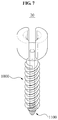
- FIG. 7 is a view illustrating a medical insertion apparatus according to another embodiment of the present invention.
- FIG. 8 is a view illustrating an electrode to be connected to a screw body in a medical insertion apparatus according to an embodiment of the present invention
- FIG. 9 is a view illustrating a medical insertion apparatus according to still another embodiment of the present invention.
- FIG. 10 is a view illustrating a medical insertion apparatus according to yet another embodiment of the present invention.
- FIG. 1 is a view illustrating a medical insertion apparatus 10 according to an embodiment of the present invention.
- FIGS. 2A and 2B are views illustrating an electrode 200 extending to be perpendicular or to incline with respect to a screw body 100 in the medical insertion apparatus 10 according to an embodiment of the present invention.
- FIGS. 3A and 3B are views illustrating the electrode 200 exposed at a plurality of positions in the medical insertion apparatus 10 according to an embodiment of the present invention.
- FIG. 4 is a view illustrating the electrode 200 having an externally exposed portion provided in a form of a ring shape in the medical insertion apparatus 10 according to an embodiment of the present invention.
- FIG. 1 is a view illustrating a medical insertion apparatus 10 according to an embodiment of the present invention.
- FIGS. 2A and 2B are views illustrating an electrode 200 extending to be perpendicular or to incline with respect to a screw body 100 in the medical insertion apparatus 10 according to an embodiment of the present invention.
- FIG. 5 is a view illustrating a through-hole provided in the screw body 100 or the electrode 200 in the medical insertion apparatus 10 according to an embodiment of the present invention.
- FIG. 6 is a view illustrating the screw body 100 provided in a form of a tapping screw in the medical insertion apparatus 10 according to an embodiment of the present invention.
- the medical insertion apparatus 10 includes the screw body 100 and the electrode 200 .
- the screw body 100 may be inserted into a body.
- a thread may be provided on an outer side of the screw body 100 .
- the screw body 100 may be inserted into a spine, a tooth, or a muscle.
- the screw body 100 may be configured in a synostosis screw to be inserted into an osseous tissue adjacent to a nerve, in particular, a pedicle screw to be inserted into a spine.
- the screw body 100 may be manufactured using titanium. Titanium is excellent in terms of biocompatibility and strength, and thus may be used as a material for a variety of implants.
- the electrode 200 is provided in a central portion of the screw body 100 .
- the electrode 200 extends in a longitudinal direction of the screw body 100 from one end of the screw body 100 to a terminal portion of the screw body 100 .
- a hole (not shown) in which the electrode 200 is to be disposed may be provided in the central portion of the screw body 100 to penetrate through the screw body 100 from the one end of the screw body 100 to the terminal portion of the screw body 100 .
- the electrode 200 may be formed using a method of filling the hole with a melted electrode material and hardening the electrode material by cooling the electrode material at room temperature.
- the hole may be filled with the melted electrode material, and the electrode material may be hardened.
- the electrode 200 may be more strongly fixed in the hole.
- the electrode 20 may be stably disposed in the screw body 100 .
- a material of the electrode 200 may include platinum, gold, silver, tungsten, and any material verified to be biocompatible and have an excellent electric conductivity, and thus be suitable for detecting a minute signal.
- the electrode 200 is externally exposed at the terminal portion of the screw body 100 .
- the medical insertion apparatus 10 may be manufactured through relatively simple molding.
- the electrode 200 may be exposed at a portion of the screw body 100 to be in contact with a nerve first.
- a nerve may be detected relatively early when the medical insertion apparatus 10 is inserted into a body.
- the electrode 200 may be exposed on an outer circumference of the screw body 100 at a position spaced apart from the terminal portion of the screw body 100 .
- the electrode 200 extends to be perpendicular from the central portion of the screw body 100 toward the outer circumference of the screw body 100 .
- the electrode 200 extending in the longitudinal direction of the screw body 100 extends in a direction perpendicular to the longitudinal direction of the screw body 100 and is externally exposed at a position spaced apart from the terminal portion of the screw body 100 on the outer circumference of the screw body 100 .
- a distance between the electrode 200 disposed in the central portion of the screw body 100 and the terminal portion of the screw body 100 may be equal to a distance between the externally exposed portion of the electrode 200 and the terminal portion of the screw body 100 .
- the electrode 200 extends to incline from the central portion of the screw body 100 toward the outer circumference of the screw body 100 .
- the electrode 200 extending in the longitudinal direction of the screw body 100 extends in a direction inclined with respect to the longitudinal direction of the screw body 100 and is externally exposed at a position spaced apart from the terminal portion of the screw body 100 on the outer circumference of the screw body 100 .
- a distance between the electrode 200 disposed in the central portion of the crew body 100 and the terminal portion of the screw body 100 may be greater than or less than a distance between the externally exposed portion of the electrode 200 and the terminal portion of the screw body 100 .
- the electrode 200 is externally exposed at a position spaced apart from the terminal portion of the screw body 100 .
- a nerve monitoring range may be broadened.
- the electrode 200 may be exposed at a plurality of positions.
- the electrode 200 is externally exposed in a radial shape on the outer circumference of the screw body 100 .
- the electrode 200 extending in the longitudinal direction of the screw body 100 extends to be perpendicular or to incline with respect to the longitudinal direction of the screw body 100 and is externally exposed at a position spaced apart from the terminal portion of the screw body 100 on the outer circumference of the screw body 100 .
- the electrode 200 extends in a radial direction from the central portion of the screw body 100 toward the outer circumference of the screw body 100 .
- the medical insertion apparatus 10 may monitor nerves in many ways with respect to the screw body 100 .
- the electrode 200 is externally exposed in a multi-stage shape on the outer circumference of the screw body 100 .
- the electrode 200 extending in the longitudinal direction of the screw body 100 extends to be perpendicular or to incline with respect to the longitudinal direction of the screw body 100 and is externally exposed at a position spaced apart from the terminal portion of the screw body 100 on the outer circumference of the screw body 100 .
- the electrode 200 extends in the multi-stage shape from the central portion of the screw body 100 toward the outer circumference of the screw body 100 .
- FIG. 3B illustrates the electrode 100 externally exposed in the multi-stage shape only at an end portion of the screw body 100 .
- a position at which the electrode 100 is externally exposed is not limited thereto.
- the electrode 100 may be externally exposed in the multi-stage shape at various positions on the outer circumference of the screw body 100 .
- the medical insertion apparatus 10 may efficiently monitor nerves positioned at different heights with respect to the screw body 100 .
- the electrode 200 may be externally exposed in a form of a ring shape.
- the electrode 200 is externally exposed in the form of a ring shape along the outer circumference of the screw body 100 and at the terminal portion of the screw body 100 .
- the externally exposed portion of the electrode 200 provided in the form of the ring shape is disposed at a position spaced apart from the terminal portion of the screw body on the outer circumference of the screw body 100 .
- the externally exposed portion of the electrode 200 provided in the form of the ring shape may be integrated with the screw body 100 , or formed separately from the screw body 100 to be detachable.
- a plurality of ring shapes may be provided.
- the plurality of ring shapes may be disposed to be spaced from each other in the longitudinal direction of the screw body 100 .
- the ring shapes may be provided at a portion of the screw body 100 .
- the ring shapes may be provided over a half of the screw body 100 .
- the ring shapes may be provided over the entire screw body 100 .
- the electrode 200 may be externally exposed over the entire screw body 100 .
- the electrode 200 extending in the longitudinal direction of the screw body 100 extends in a direction perpendicular or inclined with respect to the longitudinal direction of the screw body 100 , and is connected to the externally exposed portion of the electrode 200 provided in the form of the ring shape.
- a through-hole H is provided in a central portion of the screw body 100 or the electrode 200 .
- the through-hole H is provided in the longitudinal direction of the screw body 100 or the electrode 200 from one end of the screw body 100 or the electrode 200 toward the terminal portion of the screw body 100 .
- the through-hole H may be provided in a form of a tunnel or a small hole having a diameter of about 1 millimeter (mm)
- the through-hole H may be provided to extend from the one end of the screw body 100 or the electrode 200 in the longitudinal direction of the screw body 100 or the electrode 200 .
- the through-hole H may be provided straightly to penetrate through the electrode 200 and the terminal portion of the screw body 100 .
- the through-hole H may be provided straightly to extend in the longitudinal direction of the screw body 100 or the electrode 200 from the one end of the screw body 100 or the electrode 200 and penetrate through the terminal portion of the screw body 100 or the electrode 200 .
- the through-hole H may be referred to as being provided in the central portion of the electrode 200 , and also be referred to as being provided in the central portion of the screw body 100 .
- FIG. 5 illustrates the electrode 200 being externally exposed at a position spaced apart from the terminal portion of the screw body 100 on the outer circumference of the screw body 100 .
- a position at which the electrode 200 is externally exposed is not limited thereto.
- the electrode 200 may be externally exposed at various positions of the screw body 100 as described above.
- a guide element (not shown) may be disposed in the through-hole H provided in the electrode 200 .
- the guide element may guide an insertion of the screw body 100 into a body, and may be provided using, for example, a wire, a cable, and a string.
- a wire may be inserted into a spine to pass through the through-hole H of the screw body 100 or the electrode 200 .
- the screw body 100 may be inserted into the body along a path of the wire.
- the medical insertion apparatus 10 may be more easily inserted into a body, and a surgical stability may increase.
- the screw body 100 is provided in a form of a tapping screw T.
- the tapping screw T may be used to perform boring before the screw body 100 is inserted into a body.
- the screw body 100 may be inserted into a body more safely through a hole provided by the tapping screw T.
- the electrode 200 may be provided to be externally exposed on a side on which the tapping screw T is provided. Thus, a contact between the screw body 100 and a nerve may be detected during the boring.
- FIG. 6 illustrates the electrode 200 being exposed at the terminal portion of the screw body 100 .
- the electrode 200 may be exposed at a position spaced apart from the terminal portion of the screw body 100 on the outer circumference of the screw body 100 .
- the medical insertion apparatus 10 may increase an area of contact with nerves, thereby efficiently detecting a nerve, preventing neurological damage, increasing a surgical stability, and reducing a radiation exposure time during a surgery.
- the medical insertion apparatus 10 may be efficiently inserted into a body by means of a guide element configured to guide an insertion of a screw body into a body during a surgery.
- the medical insertion apparatus 10 may include a screw body provided in a form of a tapping screw to detect a nerve while forming a hole through which the screw body is to be inserted.
- FIG. 7 is a view illustrating a medical insertion apparatus 20 according to another embodiment of the present invention
- FIG. 8 is a view illustrating an electrode 1100 to be connected to a screw body 1000 in the medical insertion apparatus 20 according to an embodiment of the present invention.
- the medical insertion apparatus 20 includes a screw body 1000 and an electrode 1100 .
- the screw body 1000 may be inserted into a body.
- a thread may be provided on an outer side of the screw body 1000 .
- the screw body 1000 may be inserted into a spine, a tooth, or a muscle.
- the screw body 1000 may be configured in a synostosis screw to be inserted into an osseous tissue adjacent to a nerve, in particular, a pedicle screw to be inserted into a spine.
- a through-hole 1020 is provided in a central portion of the screw body 1000 .
- the through-hole 1020 is provided for an insertion of the electrode 1100 .
- a shape of the through-hole 1020 may correspond to a shape of the electrode 1100 to be disposed in the through-hole 1020 .
- the through-hole 1020 may also have a round cross-section.
- the through-hole 1020 may also be provided in a shape of a cylinder.
- the through-hole 1020 extends in a longitudinal direction of the screw body 1000 from one end of the screw body 1000 to a terminal portion of the screw body 1000 .
- a thread 1022 is provided in the through-hole 1020 at a position adjacent to the terminal portion of the screw body 1000 .
- the thread 1022 may be provided in the through-hole 1020 for screw fastening with a thread 1122 provided on the electrode 1100 , which will be described in detail later.
- the electrode 1100 may be inserted into the through-hole 1020 .
- the electrode 1100 may be inserted into the through-hole 1020 through the terminal portion of the screw body 1000 .
- the electrode 1100 may be configured as follows.
- the electrode 1100 includes a first portion 1120 extending in the longitudinal direction of the screw body 1000 , and a second portion 1140 connected to the first portion 1120 and externally exposed at the terminal portion of the screw body 1000 .
- the first portion 1120 may be disposed in the through-hole 1020 of the screw body 1000 , and the second portion 1140 may be externally exposed at the terminal portion of the screw body 1000 .
- the first portion 1120 may be provided to have a shape corresponding to a shape of the through-hole 1020
- the second portion 1140 may be provided to be greater than the through-hole 1020 .
- the second portion 1140 When the first portion 1120 is inserted into the through-hole 1020 through the terminal portion of the screw body 1000 , the second portion 1140 may be maintained to be externally exposed at the terminal portion of the screw body 1000 . Thus, the second portion 1140 may not be inserted into the through-hole 1020 .
- the thread 1122 to engage with the thread 1022 of the through-hole 1020 is provided on the first portion 1120 .
- the thread 1122 of the first portion 1120 and the thread 1022 of the through-hole 1020 are provided at corresponding positions.
- the thread 1122 of the first portion 1120 and the thread 1022 of the through-hole 1020 may be disposed to be adjacent to the terminal portion of the screw body 1000 .
- the second portion 1140 is externally exposed at the terminal portion of the screw body 1000 .
- a contact between the electrode 1100 and the nerve or muscle may be detected.
- the medical insertion apparatus 20 may be used by being connected to a nerve stimulating and monitoring apparatus.
- the nerve stimulating and monitoring apparatus may include an apparatus for electromyography (EMG), an evoked potential (EP) test, a motor evoked potential (MEP) test, and a somatosensory evoked potential (SSEP) test.
- EMG electromyography
- EP evoked potential
- MEP motor evoked potential
- SSEP somatosensory evoked potential
- the nerve stimulating and monitoring apparatus is not limited thereto.
- the nerve stimulating and monitoring apparatus may include any apparatus configured to provide an electrical stimulus to a muscle or nerve, and receive or detect a signal generated in the muscle or nerve in response to the electrical stimulus.
- the electrode 1100 provided in the medical insertion apparatus 20 may be connected to the nerve stimulating and monitoring apparatus to apply a minute current directly to a nerve.
- a current may be applied to the nerve and a signal may be generated in the nerve or muscle.
- the generated signal is detected by the nerve stimulating and monitoring apparatus, it may be understood that the medical insertion apparatus 20 is in contact with a nerve.
- the current may be transmitted through the first portion 1120 to the second portion 1140 , and the second portion 1140 may be in contact with the nerve or muscle.
- the electrode 1100 of the medical insertion apparatus 20 may be connected to the screw body 1000 as follows.
- a top end of the first portion 1120 of the electrode 1100 may be inserted into the through-hole 1020 through the terminal portion of the screw body 1000 .
- the thread 1022 of the through-hole 1020 and the tread 1122 of the first portion 1120 may be in contact with each other.
- the second portion 1140 Since the second portion 1140 is provided to be greater than the through-hole 1020 , the second portion 1140 may not be inserted into the through-hole 1020 . Thus, the second portion 1140 may be in contact with the terminal portion of the screw body 1000 .
- the electrode 1100 may rotate with respect to the screw body 1000 to enable screw fastening between the thread 1022 of the through-hole 1020 and the thread 1122 of the first portion 1120 .
- one end of the screw body 1000 and one end of the first portion 1120 may be disposed at identical heights.
- the aforementioned nerve stimulating and monitoring apparatus may transmit a current from the through-hole 1020 through the exposed end portion of the first portion 1120 .
- the electrode 1100 of the medical insertion apparatus 20 may be separated from the screw body 1000 as follows.
- the electrode 1100 may rotate with respect to the screw body 1000 in a direction opposite to a direction in which the electrode 1100 rotates with respect to the screw body 1000 to fasten the screw body 1000 and the electrode 1100 together.
- the screw fastening between the tread 1022 of the through-hole 1020 and the tread 1122 of the first portion 1120 may be released, and the first portion 1120 may be pulled out from the terminal portion of the screw body 1000 .
- the second portion 1140 is provided to be greater than the through-hole 1020 , the second portion 1140 may not be inserted into the through-hole 1120 , and the first portion 1120 may not be separated from the screw body 1000 through the one end of the screw body 1000 .
- the screw body 1000 and the electrode 1100 may be easily connected to or separated from each other.
- the medical insertion apparatus 20 may not need to be inserted into the screw body 1000 .
- the screw body 1000 and the electrode 1100 may be provided using materials having similar melting points.
- the medical insertion apparatus 20 may be processed in a form of an assembly, whereby a defect rate may decrease, processing may be easy, and an overall unit cost of production may decrease.
- FIG. 9 is a view illustrating the medical insertion apparatus 30 according to still another embodiment of the present invention.
- the medical insertion apparatus 30 includes a screw body 2000 and an electrode 2100 .
- the medical insertion apparatus 30 differs from the medical insertion apparatus 20 in that the electrode 2100 is detachably provided.
- the electrode 2100 includes a third portion 2120 and a fourth portion 2140 .
- the electrode 2100 may include platinum, gold, silver, and tungsten, which are biocompatible and excellent in electric conductivity.
- the third portion 2120 extends in a longitudinal direction of the screw body 2000 toward one side of the screw body 2000 .
- a recessed element 2122 is provided at an end portion of the third portion 2120 disposed at a terminal portion of the screw body 2000 .
- the recessed element 2122 may be provided to fasten the third portion 2120 and the fourth portion 2130 together.
- a thread may be provided on an inner side surface of the recessed element 2122 .
- the fourth portion 2140 externally protrudes at the terminal portion of the screw body 2000 .
- FIG. 9 illustrates the fourth portion 2140 being disposed at the terminal portion of the screw body 2000 .
- a position of the fourth portion 2140 is not limited thereto.
- the fourth portion 2140 may be disposed at a position spaced apart from the terminal portion of the screw body 2000 .
- a protruding element 2142 may be provided at an end portion of the fourth portion 2140 to be connected to the third portion 2120 .
- the protruding element 2142 may be provided to fasten the fourth portion 2140 to the recessed portion 2122 of the third portion 2120 .
- a thread may be provided on an outer side surface of the protruding element 2142 .
- the recessed element 2122 provided in the third portion 2120 of the electrode 2000 and the protruding element 2142 provided in the fourth portion 2140 of the electrode 2000 may be provided symmetrically. Through screw fastening therebetween, the third portion 2120 and the fourth portion 2140 may be connected to or separated from each other.
- third portion 2120 and the fourth portion 2140 may be connected to each other through interference fit, rather than screw fastening.
- the externally exposed portion of the electrode 2000 may be provided in a replaceable structure in the medical insertion apparatus 30 .
- the electrode 2000 may be easily maintained.
- FIG. 10 is a view illustrating the medical insertion apparatus 40 according to yet another embodiment of the present invention.
- the medical insertion apparatus 40 includes a screw body 3000 and an electrode 3100 .
- a through-hole 3020 is provided in an internal portion of the screw body 3000 for an insertion of the electrode 3100 .
- the through-hole 3020 is provided to extend in a longitudinal direction of the screw body 3000 from one end of the screw body 3000 to a terminal portion of the screw body 3000 .
- a thread may be provided on an inner side surface of the through-hole 3020 .
- the thread of the through-hole 3020 may be provided for screw fastening with a thread provided on an outer side surface of the electrode 3100 .
- the thread of the through-hole 3000 may be provided to correspond to the thread provided on the outer side surface of the electrode 3100 .
- the electrode 3100 may be inserted into the through-hole 3020 through the one end of the screw body 3000 .
- the one end of the screw body 3000 refers to an opposite side of the terminal portion of the screw body 3000 .
- the electrode 3100 may be provided in a shape corresponding to a shape of the through-hole 3020 .
- the electrode 3100 may be externally exposed at the terminal portion of the screw body 3000 .
- a guide recess 3040 and a guide protrusion 3120 may be provided symmetrically at the one end of the screw body 3000 and one end of the electrode 3100 , respectively.
- FIG. 10 illustrates the guide recess 3040 being provided at the screw body 3000 and the guide protrusion 3120 being provided at the electrode 3100 , it is obvious that the guide protrusion 3120 may also be provided at the screw body 3000 and the guide recess 3040 may also be provided at the electrode 3100 .
- the screw body 3000 and the electrode 3100 may be provided in a connectable or separable structure.
- the electrode 3100 may be easily connected to or separated from the screw body 3000 .
- the screw body 3000 and the electrode 3100 may be provided using materials having similar melting points.
Landscapes
- Health & Medical Sciences (AREA)
- Life Sciences & Earth Sciences (AREA)
- Orthopedic Medicine & Surgery (AREA)
- Surgery (AREA)
- Veterinary Medicine (AREA)
- Public Health (AREA)
- General Health & Medical Sciences (AREA)
- Animal Behavior & Ethology (AREA)
- Engineering & Computer Science (AREA)
- Biomedical Technology (AREA)
- Heart & Thoracic Surgery (AREA)
- Neurology (AREA)
- Medical Informatics (AREA)
- Molecular Biology (AREA)
- Nuclear Medicine, Radiotherapy & Molecular Imaging (AREA)
- Physics & Mathematics (AREA)
- Pathology (AREA)
- Biophysics (AREA)
- Cardiology (AREA)
- Radiology & Medical Imaging (AREA)
- Neurosurgery (AREA)
- Oral & Maxillofacial Surgery (AREA)
- Dentistry (AREA)
- Epidemiology (AREA)
- Electrotherapy Devices (AREA)
- Measurement And Recording Of Electrical Phenomena And Electrical Characteristics Of The Living Body (AREA)
- Surgical Instruments (AREA)
Abstract
Description
Claims (4)
Applications Claiming Priority (14)
| Application Number | Priority Date | Filing Date | Title |
|---|---|---|---|
| KR1020130101078 | 2013-08-26 | ||
| KR20130101078 | 2013-08-26 | ||
| KR1020140028345 | 2014-03-11 | ||
| KR1020140028345A KR101599603B1 (en) | 2013-08-26 | 2014-03-11 | Medical inserting apparatus |
| KR1020140028921A KR101563420B1 (en) | 2013-08-26 | 2014-03-12 | Medical inserting apparatus |
| KR1020140028921 | 2014-03-12 | ||
| KR1020140034210A KR101605950B1 (en) | 2013-08-26 | 2014-03-24 | Medical inserting apparatus |
| KR1020140034202 | 2014-03-24 | ||
| KR1020140034206 | 2014-03-24 | ||
| KR1020140034202A KR101547759B1 (en) | 2013-08-26 | 2014-03-24 | Medical inserting apparatus |
| KR1020140034210 | 2014-03-24 | ||
| KR1020140034203 | 2014-03-24 | ||
| KR1020140034203A KR101605949B1 (en) | 2013-08-26 | 2014-03-24 | Medical inserting apparatus |
| KR1020140034206A KR101609440B1 (en) | 2013-08-26 | 2014-03-24 | Medical inserting apparatus |
Publications (2)
| Publication Number | Publication Date |
|---|---|
| US20150057711A1 US20150057711A1 (en) | 2015-02-26 |
| US10702322B2 true US10702322B2 (en) | 2020-07-07 |
Family
ID=52480983
Family Applications (2)
| Application Number | Title | Priority Date | Filing Date |
|---|---|---|---|
| US14/467,837 Active 2036-08-06 US10702322B2 (en) | 2013-08-26 | 2014-08-25 | Medical insertion apparatus |
| US14/467,861 Active 2035-05-07 US10172658B2 (en) | 2013-08-26 | 2014-08-25 | Medical insertion apparatus |
Family Applications After (1)
| Application Number | Title | Priority Date | Filing Date |
|---|---|---|---|
| US14/467,861 Active 2035-05-07 US10172658B2 (en) | 2013-08-26 | 2014-08-25 | Medical insertion apparatus |
Country Status (2)
| Country | Link |
|---|---|
| US (2) | US10702322B2 (en) |
| WO (1) | WO2015030409A1 (en) |
Families Citing this family (10)
| Publication number | Priority date | Publication date | Assignee | Title |
|---|---|---|---|---|
| WO2011054124A1 (en) * | 2009-11-09 | 2011-05-12 | Spinewelding Ag | Medical device, apparatus, and surgical method |
| US20180036053A1 (en) * | 2016-08-03 | 2018-02-08 | Elisandro R. Toscano | Dental / Prosthetic Implant |
| US10751527B2 (en) | 2016-10-03 | 2020-08-25 | II Erich W. Wolf | Device and method for percutaneous placement and anchoring of stimulating electrodes in spine |
| WO2018144297A1 (en) | 2017-02-01 | 2018-08-09 | Avent, Inc. | Emg guidance for probe placement, nearby tissue preservation, and lesion confirmation |
| US10307194B2 (en) * | 2017-08-01 | 2019-06-04 | Warsaw Orthopedic, Inc. | Spinal implant and method of manufacture |
| CN107496021B (en) * | 2017-08-03 | 2019-09-10 | 中国人民解放军第二军医大学第二附属医院 | Pedicle screw is placed in dynamic monitoring system and method |
| CN108392245B (en) * | 2018-02-11 | 2019-10-18 | 袁志峰 | A kind of bone surgery synthetism auxiliary machine |
| KR102035265B1 (en) * | 2018-02-26 | 2019-10-22 | 사회복지법인 삼성생명공익재단 | The screw type electrode which is connected to a plug type wire |
| CN116020054B (en) * | 2023-02-24 | 2023-12-08 | 北京微脊医疗科技有限公司 | Implantable electric field therapy device |
| US12035953B1 (en) * | 2023-11-08 | 2024-07-16 | Spinal Simplicity, Llc | Bony fusion implant, insertion instrument, and methods |
Citations (6)
| Publication number | Priority date | Publication date | Assignee | Title |
|---|---|---|---|---|
| US20040243207A1 (en) | 2003-05-30 | 2004-12-02 | Olson Donald R. | Medical implant systems |
| US20080125637A1 (en) * | 2006-09-21 | 2008-05-29 | Wyatt Drake Geist | Implant equipped for nerve location and method of use |
| US20090125072A1 (en) * | 2007-11-13 | 2009-05-14 | Neubardt Seth L | Surgical bone screw construction |
| US20100106198A1 (en) * | 2008-10-23 | 2010-04-29 | Warsaw Orthopedic, Inc | Nerve stimulating bone screw |
| US20110144702A1 (en) | 2004-04-20 | 2011-06-16 | Spineco, Inc. | Implant device |
| US20160038205A1 (en) * | 2014-08-07 | 2016-02-11 | Jeffrey Scott Smith | Pedicle screw with electro-conductive coating or portion |
Family Cites Families (11)
| Publication number | Priority date | Publication date | Assignee | Title |
|---|---|---|---|---|
| EP1478283B1 (en) * | 2002-02-25 | 2010-07-14 | Jeffrey E. Yeung | Expandable fastener with compressive grips |
| KR100563138B1 (en) * | 2003-08-29 | 2006-03-21 | (주)태연메디칼 | Pedicle screw |
| KR200367241Y1 (en) * | 2004-08-27 | 2004-11-10 | 진동규 | Spinal fixation apparatus |
| US7559929B2 (en) * | 2005-02-18 | 2009-07-14 | Warsaw Orthopedic, Inc. | Implants and methods for positioning same in surgical approaches to the spine |
| KR101157312B1 (en) | 2007-01-25 | 2012-07-03 | 워쏘우 오르쏘페딕 인코포레이티드 | Surgical navigational and neuromonitoring instrument |
| US20110264151A1 (en) * | 2010-04-26 | 2011-10-27 | Timothy Davis | Bone fixation device and method of validating its proper placement |
| KR101318844B1 (en) * | 2010-11-27 | 2013-10-17 | 서울대학교산학협력단 | Implant for neurotization by lectrostimulation |
| KR101191743B1 (en) | 2010-12-28 | 2012-10-15 | 재단법인 포항산업과학연구원 | Method for Leaching Magnesium from Ferronickel Slag |
| US20120185001A1 (en) * | 2011-01-14 | 2012-07-19 | Warsaw Orthopedic, Inc. | Bone Anchors Compatible for Use with Neural Integrity Monitoring Systems and Procedures |
| KR20140003243A (en) | 2012-06-29 | 2014-01-09 | 덴토즈 주식회사 | Dental implant |
| KR101356048B1 (en) | 2012-07-09 | 2014-02-27 | 주식회사 미소메디텍 | Pedicle Screw |
-
2014
- 2014-08-19 WO PCT/KR2014/007664 patent/WO2015030409A1/en not_active Ceased
- 2014-08-25 US US14/467,837 patent/US10702322B2/en active Active
- 2014-08-25 US US14/467,861 patent/US10172658B2/en active Active
Patent Citations (6)
| Publication number | Priority date | Publication date | Assignee | Title |
|---|---|---|---|---|
| US20040243207A1 (en) | 2003-05-30 | 2004-12-02 | Olson Donald R. | Medical implant systems |
| US20110144702A1 (en) | 2004-04-20 | 2011-06-16 | Spineco, Inc. | Implant device |
| US20080125637A1 (en) * | 2006-09-21 | 2008-05-29 | Wyatt Drake Geist | Implant equipped for nerve location and method of use |
| US20090125072A1 (en) * | 2007-11-13 | 2009-05-14 | Neubardt Seth L | Surgical bone screw construction |
| US20100106198A1 (en) * | 2008-10-23 | 2010-04-29 | Warsaw Orthopedic, Inc | Nerve stimulating bone screw |
| US20160038205A1 (en) * | 2014-08-07 | 2016-02-11 | Jeffrey Scott Smith | Pedicle screw with electro-conductive coating or portion |
Also Published As
| Publication number | Publication date |
|---|---|
| US10172658B2 (en) | 2019-01-08 |
| WO2015030409A1 (en) | 2015-03-05 |
| US20150057711A1 (en) | 2015-02-26 |
| US20150057564A1 (en) | 2015-02-26 |
Similar Documents
| Publication | Publication Date | Title |
|---|---|---|
| US10702322B2 (en) | Medical insertion apparatus | |
| KR101609440B1 (en) | Medical inserting apparatus | |
| CN101951848B (en) | Implant equipped for nerve location and method of use | |
| US9308365B2 (en) | Detachable electrode and anchor | |
| AU2006218387B2 (en) | Instruments and methods for nerve monitoring in spinal surgical procedures | |
| US9155880B2 (en) | Electrode with movable insertion stopper | |
| JP5914771B2 (en) | Osteosynthesis and osteosynthesis | |
| JP2008510549A (en) | Implants including one or more electrodes and associated insertion devices | |
| KR20100031715A (en) | Transcranial electrical stimulation device | |
| US10751527B2 (en) | Device and method for percutaneous placement and anchoring of stimulating electrodes in spine | |
| US20190167985A1 (en) | Devices and methods for treating tinnitus using electrical stimulation | |
| EP3120797A3 (en) | Method for identifying the optimal direction and maximum diameter of a pedicle screw | |
| US10136999B2 (en) | Surgical implant, and associated installation tool, surgical kit and method of production | |
| CN105636642A (en) | Leadless cardiac pacemaker with delivery and/or retrieval features | |
| US20220023620A1 (en) | System and method for percutaneous lead anchoring | |
| CN112888477B (en) | Stimulation probe assembly and method of use | |
| CN217066535U (en) | Carrier terminal and subcutaneous implantation tool | |
| US11771464B2 (en) | Probes for surgical access system | |
| KR102205668B1 (en) | Medical inserting apparatus and method for manufacturing the same | |
| KR101575948B1 (en) | Medical current test apparatus | |
| KR102144041B1 (en) | Medical inserting apparatus and neuromonitoring system including the same | |
| KR20180066604A (en) | Mounted Scalp Acupuncture Needle System for Long-term Brain stimulation |
Legal Events
| Date | Code | Title | Description |
|---|---|---|---|
| AS | Assignment |
Owner name: KYUNGPOOK NATIONAL UNIVERSITY INDUSTRY-ACADEMIC COOPERATION FOUNDATION, KOREA, REPUBLIC OF Free format text: ASSIGNMENT OF ASSIGNORS INTEREST;ASSIGNOR:KIM, KYOUNG TAE;REEL/FRAME:033607/0283 Effective date: 20140825 Owner name: KYUNGPOOK NATIONAL UNIVERSITY INDUSTRY-ACADEMIC CO Free format text: ASSIGNMENT OF ASSIGNORS INTEREST;ASSIGNOR:KIM, KYOUNG TAE;REEL/FRAME:033607/0283 Effective date: 20140825 |
|
| STPP | Information on status: patent application and granting procedure in general |
Free format text: ADVISORY ACTION MAILED |
|
| STPP | Information on status: patent application and granting procedure in general |
Free format text: DOCKETED NEW CASE - READY FOR EXAMINATION |
|
| STPP | Information on status: patent application and granting procedure in general |
Free format text: NON FINAL ACTION MAILED |
|
| STPP | Information on status: patent application and granting procedure in general |
Free format text: RESPONSE TO NON-FINAL OFFICE ACTION ENTERED AND FORWARDED TO EXAMINER |
|
| STPP | Information on status: patent application and granting procedure in general |
Free format text: NOTICE OF ALLOWANCE MAILED -- APPLICATION RECEIVED IN OFFICE OF PUBLICATIONS |
|
| STPP | Information on status: patent application and granting procedure in general |
Free format text: PUBLICATIONS -- ISSUE FEE PAYMENT VERIFIED |
|
| STCF | Information on status: patent grant |
Free format text: PATENTED CASE |
|
| MAFP | Maintenance fee payment |
Free format text: PAYMENT OF MAINTENANCE FEE, 4TH YR, SMALL ENTITY (ORIGINAL EVENT CODE: M2551); ENTITY STATUS OF PATENT OWNER: SMALL ENTITY Year of fee payment: 4 |