US1069861A - Tea-leaf rolling and mixing machine. - Google Patents
Tea-leaf rolling and mixing machine. Download PDFInfo
- Publication number
- US1069861A US1069861A US60690211A US1911606902A US1069861A US 1069861 A US1069861 A US 1069861A US 60690211 A US60690211 A US 60690211A US 1911606902 A US1911606902 A US 1911606902A US 1069861 A US1069861 A US 1069861A
- Authority
- US
- United States
- Prior art keywords
- container
- blade
- tea
- rotary
- base
- Prior art date
- Legal status (The legal status is an assumption and is not a legal conclusion. Google has not performed a legal analysis and makes no representation as to the accuracy of the status listed.)
- Expired - Lifetime
Links
Images


Classifications
-
- A—HUMAN NECESSITIES
- A23—FOODS OR FOODSTUFFS; TREATMENT THEREOF, NOT COVERED BY OTHER CLASSES
- A23G—COCOA; COCOA PRODUCTS, e.g. CHOCOLATE; SUBSTITUTES FOR COCOA OR COCOA PRODUCTS; CONFECTIONERY; CHEWING GUM; ICE-CREAM; PREPARATION THEREOF
- A23G1/00—Cocoa; Cocoa products, e.g. chocolate; Substitutes therefor
- A23G1/04—Apparatus specially adapted for manufacture or treatment of cocoa or cocoa products
- A23G1/10—Mixing apparatus; Roller mills for preparing chocolate
Description
s. c. DAVIDSON. TBA LEAF ROLLING AND MIXING MAGHINE.
APPLIOATION FILED r1113. 6, 1911.
"Patented Aug. 12, 1913.
6 SHEETS-$153151 1.
l V/IVs 123555: i I H //V-V /YTOR:
S. G. DAVIDSON.
TEA LEAF ROLLING AND MIXING MACHINE. APPLICATION FILED I'EB.6,1911.
Lmfi fimn Patented Aug.12,1913.
5 SHEETSSHEET 2.
s. c. DAVIDSON. TEA LEAP ROLLING AND MIXING MACHINE.
APPLICATION FILED IEB. 6,1911.
Patented Aug. 12, 1913.
6 SHEETS-SHEET 3.
S. G. DAVIDSON. TEA LEAF ROLLING AND MIXING MACHINE.
APPLICATION FILED FEB. 6,1911.
1,69 861 u Patented Au 12, 1913.
5 SHEETS-SHEET 4.
r S. O. DAVIDSON.
TEA LEAP ROLLING AND MIXING MACHINE. APPLICATION FILED FEB. s, 1911 Patented Aug". 12, 1913.
6 SHEETS-SHEET 5.
lac
i0. a general lif fami .efl"ct produced by t 9 actio the mtary EINETEEF %TA EE% PATENT @FFEQE.
SAMUEL entrain: navmsori, 0 F BELFAST, warm.
rue-Lear MLLI-NG AND mrxme macnmn.
Specification of Letters Patent.
Application filed February 6, 1911. Serial No. 6045902.
To all whom it may concern:
Be it known that I, SAMUEL CLELAND DAVIDSON, of Sirocco Engineering Works, Belfast, Ireland, merchant, have invented certain new and useful Improvements in Tea-Leaf Rolling and Mixing Machines, of which the follbwing'is' a specification.
This invention relates to tea leaf rolling and analogous machines of the kind wherein a container for the material to be dealt with is employed having withinit a helical screw form of blade or device adapted for rotation about a central vertical axis as. described in my prior Patent No. 980,213. In such :1}: aratus certain devices are usually employe for retarding or artially checking any tendency of the teaeaf in the container to rotate as a mass under theaction of the beforelnentioned rotary device. Two or more of these rotary devices. may, in some cases, be employed within one pontainer of appropriate shape. 'l he said. ma chines and the hereinafter described improvements besides being useiul as a tea. leaf rolling machme for which same were originally designed may also be used for operating upon analogous materials.
It is the object of the piesent invention to provide an apparatus which will give a,
morepositive an rapid circulation the tea; leaf up the center of the container and down the side, as partof or supplemental and roing helical or equivalent device or devices.
Acc r ing o. the p v n on ploy anelongated blade orbladesof greater length than width" and er b n pitch that the working surface oi the blade or blades.
passes from the base to the top one revo; lution or less, in combination, with a, container the walls oiwhich are so shaped that a tapering annular; space wider at the top than at the base isl leftbetween the walls of the ta ner a d." he p th e c e by the travel of the outer edge, of; theirotary' Y helical blade orhlades'. Ear examplea ver 'tical or inclined and preferably cylindrical a ai e ha withi it r tary bl or device. efygreaterjheight than width and.
of helical or equivalent acting shape, or combination! of such devices, having the upper part or parts of less radius than-the lower part. or parts and tapering npward with a pitch so increasing that. the operative surf ce. ehangfi from a s w- P tch at the Patented Aug. 12, teas.
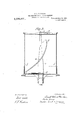
simultaneously therewith, or forming a part of such action, a positive upward motion of the leaf which forms thecentral core of the mass of material within. the container, while the material around the circumference of the container has a falling or downward motion. y r v Ref erring to the drawings: Figure 1 is an elevation of one form of rotary blade made.
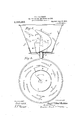
in accordance with my invention; Fig. 2 is a planet Fig. 1;. Fig. 3 is a sectional eleva- -tion of a container showing a modified; form. -w,l1ere the boss of the rotary blade is sup :pprted' at both ends; Fig. 4; is. a sectional elevation of a modified container and blade; Fig'. 5 is a'plan of; same; Figs; 6 and 7 are similar views tolfigs. 1 and 2 showing-one :method of constructing 'a composite blade having the. general form of the-blade shown in l; andZ; and Figs. 8 and'9 are lar views to Figs. 1 and 2 showing another .method: of constructing a composite blade laving the general form of blade shown in a L. A
; he ous u o o n n 1- and he improve ro y. he a blade a .i
shaped asv a tapering. helix wider at the base than, at the topof more or less concave section on its front or leading surface; 6,- the blad a being-carried up to a considerable e g T n. the c tainer and. n s me-ca es j right p the. op ereii the de: i preferab y p y ded wi ngat ,hub a Wbibh. may extend from he flew r the mtam riupwar ica greater at 18-155 The hub c e" a P I B oi t e a e. merged into the blade afor a suitable propor ion o the ngt shown. in Fig. 35, a e
t e 1b 0 m y be tend d. ey nd t e est te pp rte at bo h ends a t lower. end by the bearingd and at the upper nd by th ear ng a an r ss ar e'- f blade'e. may terminat i a mewhat round} e re pt ca t plf an which may termed a wing l-ike tip yi g one side of the entra s o wh ch the blad r tat such. wing-like tip. i of uitab e curvature in cross sectien and its lead i g or outer edge. 9. is preferably. so 7 made that when efitting itha lead in r ati n t its inner edge g'.' The base it ei the blade or or its that part which is near to and travels over the floor of the container is preferably made of such a width as to come close to the side or wall of the container 7' and thereby insure in each'revolution thereof a lifting and falling action on the tea-leaf over the entire surfaceof the floor of the container and also an effectively complete discharge of the contained material through thedoor is in the side when the same is opened (Figs. 4 and 5). The container jis preferably circular in horizontal cross. section, but it is to be understood that it may be of polygonal, square, oblong, trefoil, or other shape adapted for the use of one or more of the rotary devices described, and the walls of the container may be inclined inwardly or outwardly or they may be parallel.
In another modification shown in Figs. 4 and 5 I may'employ, a rotary helical device a of the same radius, or substantially equal radius from top to bottom, and fit same in a container 1' having the wall y" thereof flaredo'r outwardly inclined toward the top end. L As shownin Figs. 6 and 7 and 8 and 9 I may also alternatively construct the said rotary helical device in the form of a succession of blade-like members a a a and a of suitable length projecting from a central column or axis 0 and with their operative surface at an inclination to the floor of the container, and. so formed and arranged that the combination of said projections, one above the other, will operate substantially in the manner of a helical blade. As shown in Figs. 6. and 7 the several bladelike members a30 a? and a may be made in one with or attached to flanges m m on a central column or axis cor as shown in Figs. 8. and 9 a series of separate blade-like members a, a a and afimaty be provided with suitable hubs or bosses at and assembled upon a central shaft 0 (Figs. 8 and 9). The retarding devices 0 on the innerisurface of the container may be of the special form herein illustrated, or they may be of convex or triangular or of rectangular cross section W with their ends andj sides suitably beveled double and trip ofl and they may be arrange'd in one or more 'superimposed rows around the inner surface of the. container j.
I In addition to the above I may use other equivalently acting retarding devices or may take advanta e of any bolts or rivets used to fasten the sides of the container to the socket surrounding its base to provide additional retarding devices by arranging for the rivet or bolt heads to project into the container above the path of the widest portion of the base of the helical rota de 0c. The present invention is also appli'ca le to the double and multiple forms of machine before referred to and for example as shown in 1e form in my before mentioned prior patent. I
1,oce,se1
What I claimas my invention, and desire to secure by Letters Patent, is
1. A tea-leaf mixing and rolling machine, comprising a container and a rotary device therein adapted to rotate'in a direction to lift material in the container, having a helical blade of greater height than width,pro gressively increasing in pitch, and extends from its base to its top in notmore than one revolution.
2. A tea-leaf rolling machine comprising a rotary helical blade, said blade being of greater height than width and of such pitch that the working surface thereof extends from the base to the top in not more than one revolution, and a container between the walls of which and 'the path described by the travel of the outer edge of said rotary helical blade is left a tapering annular space wider at the top than at the base, said rotary blade being rotatable in a direction to lift material contained in said'container.
3: A tea-leaf rolling machine comprising a rotary helical blade'progressiv ely increasing in pitch, said blade being of greater height than width and of such pit h that the working surface thereof extends from the base to the top in not more than one revolution, and a container between the walls of which and the path described by the travel of the outer edge of said rotary helical blade is left a tapering annular space wider at the top than at, the base,'said rotary blade being rotatable in a direction to lift material contained in said container.
4:. A tea-leaf rolling machine comprising a rotary helical blade of greater height than width, wider at the base than at the top and tapering upward with a pitch increasing from a slow pitch at the base to a quicker or more vertical pitch at the top in not 'more than one revolution, and a'container in a direction to lift material contained in i said container.
5. A tea-leaf rolling machine comprising a rotary helical blade of greater height than width and of such pitch that the working surface thereof passes from the base to the top in not more than one revolution, said blade terminating at its upper end in a wing-like tip lying to one side of the central axis on whichythe blade rotates, and a container between the wallsof which and the path described by the travel of the outer edge of the rotary helicalblade is left a tapering annular space wider at the top than at the base, said rotary blade being rotatable in a direction to lift material contained in said container.
i 6. A tea-leaf rolling machine comprising a rotary helical blade of greater height than width progressively increasing in pitch, and of such pitch that the working surface thereof passes from the base to the top in not more than one revolution, said blade having its outer edge curved or rounded over, and a container between the walls of which and the path described by the travel of the outer edge of the rotary helical blade is left a tapering annular space wider at the top than at the base, said rotary blade being rotatable in a direction to lift material contained in said container.
7. A tea-leaf rolling machine comprising a rotary helical blade of greater height than width and of such pitch that the working surface thereof passes from the base to the top in not more than one revolution, and a container the walls of which are so shaped that a tapering annular space wider at the top than at the base is left between the walls of the container and the path described by the travel of the outer edge of the rotary helical blade or blades, said container being provided with retarding devices comprising a number of rib or bar-like projections inclined tothe base of the container and arranged in superimposed rows with suitable spaces between the high ends of the bars in one row and the lower ends of those in the same row, said rotary blade being rotatable in a direction to lift material contained in said container.
8. A tea-leaf mixing and rolling machine, comprising a container and rotary device therein adapted'to rotate in a direction to lift material in the container, having a helical blade of greater height than width, progressively increasing in pitch, and extends from its base to'its top in not more than one revolution, said blade being tapered toward its top, whereby an annular tapered space is left between the blade and the container.
In witness whereof, I have hereunto signed my name in the presence of two subscribing Witnesses.
SAMUEL OLELAND DAVIDSON. Witnesses:
GEORGE Goon) WARD, JOHN JOHNSON.
Priority Applications (1)
| Application Number | Priority Date | Filing Date | Title |
|---|---|---|---|
| US60690211A US1069861A (en) | 1911-02-06 | 1911-02-06 | Tea-leaf rolling and mixing machine. |
Applications Claiming Priority (1)
| Application Number | Priority Date | Filing Date | Title |
|---|---|---|---|
| US60690211A US1069861A (en) | 1911-02-06 | 1911-02-06 | Tea-leaf rolling and mixing machine. |
Publications (1)
| Publication Number | Publication Date |
|---|---|
| US1069861A true US1069861A (en) | 1913-08-12 |
Family
ID=3138098
Family Applications (1)
| Application Number | Title | Priority Date | Filing Date |
|---|---|---|---|
| US60690211A Expired - Lifetime US1069861A (en) | 1911-02-06 | 1911-02-06 | Tea-leaf rolling and mixing machine. |
Country Status (1)
| Country | Link |
|---|---|
| US (1) | US1069861A (en) |
Cited By (2)
| Publication number | Priority date | Publication date | Assignee | Title |
|---|---|---|---|---|
| US4893940A (en) * | 1987-03-09 | 1990-01-16 | Waisberg Stephen L | Stirrer device for a beverage pitcher, and beverage pitcher incorporating such a stirrer device |
| US20080148949A1 (en) * | 2006-12-21 | 2008-06-26 | David Stephen Wolfe | Blending jar apparatus structured according to the geometric relationship known as Phi |
-
1911
- 1911-02-06 US US60690211A patent/US1069861A/en not_active Expired - Lifetime
Cited By (2)
| Publication number | Priority date | Publication date | Assignee | Title |
|---|---|---|---|---|
| US4893940A (en) * | 1987-03-09 | 1990-01-16 | Waisberg Stephen L | Stirrer device for a beverage pitcher, and beverage pitcher incorporating such a stirrer device |
| US20080148949A1 (en) * | 2006-12-21 | 2008-06-26 | David Stephen Wolfe | Blending jar apparatus structured according to the geometric relationship known as Phi |
Similar Documents
| Publication | Publication Date | Title |
|---|---|---|
| DE865944C (en) | Device for producing artificial fibers, in particular glass fibers, from viscous masses by centrifugation | |
| US1069861A (en) | Tea-leaf rolling and mixing machine. | |
| DE102008032073A1 (en) | Swing-out unit for a centrifuge | |
| US1098325A (en) | Grinding and reducing apparatus. | |
| DE2255417A1 (en) | IMPACT OR IMPACT CRUSH | |
| DE2207595A1 (en) | MILL FOR GRINDING, REFINING, HOMOGENIZING AND KNEDING DRY OR DOUGH PRODUCTS | |
| EP3571411B1 (en) | Pump impeller | |
| DE102012220249B4 (en) | Guide vane, turbomachine and inner ring | |
| EP2846667A1 (en) | Mixer | |
| DE2744053C2 (en) | Pulper for breaking up waste paper | |
| US858354A (en) | Peat-machine. | |
| KR101189825B1 (en) | Capsule filling machine | |
| DE2261808C2 (en) | ||
| DE8131506U1 (en) | CRUSHING DEVICE | |
| DE529396C (en) | Sieving centrifugal mill | |
| DE477319C (en) | Blading for impellers of steam and gas turbines, in which the propellant flows through the blades in all stages in the same axial direction | |
| US980213A (en) | Tea-leaf-rolling machine. | |
| DE459965C (en) | Process for the production of objects from two or more metals by centrifugal casting | |
| AT381245B (en) | Impact mill for comminuting rock and the like | |
| US1795252A (en) | Churn | |
| DE1757399B2 (en) | Rotating container mill | |
| EP2474256A1 (en) | Spice mill with a grinder | |
| WO2019011411A1 (en) | Flywheel mass with pockets which are filled with filler material | |
| DE1960922A1 (en) | Impeller for a centrifugal fan | |
| EP4112924A1 (en) | Rotor for a wind turbine and method for operating a wind turbine |