US10697128B2 - Method and apparatus for switching device - Google Patents
Method and apparatus for switching device Download PDFInfo
- Publication number
- US10697128B2 US10697128B2 US15/566,519 US201515566519A US10697128B2 US 10697128 B2 US10697128 B2 US 10697128B2 US 201515566519 A US201515566519 A US 201515566519A US 10697128 B2 US10697128 B2 US 10697128B2
- Authority
- US
- United States
- Prior art keywords
- clip
- rail end
- end point
- assembly
- slot
- Prior art date
- Legal status (The legal status is an assumption and is not a legal conclusion. Google has not performed a legal analysis and makes no representation as to the accuracy of the status listed.)
- Active, expires
Links
Images


Classifications
-
- E—FIXED CONSTRUCTIONS
- E01—CONSTRUCTION OF ROADS, RAILWAYS, OR BRIDGES
- E01B—PERMANENT WAY; PERMANENT-WAY TOOLS; MACHINES FOR MAKING RAILWAYS OF ALL KINDS
- E01B7/00—Switches; Crossings
- E01B7/02—Tongues; Associated constructions
-
- B—PERFORMING OPERATIONS; TRANSPORTING
- B61—RAILWAYS
- B61L—GUIDING RAILWAY TRAFFIC; ENSURING THE SAFETY OF RAILWAY TRAFFIC
- B61L5/00—Local operating mechanisms for points or track-mounted scotch-blocks; Visible or audible signals; Local operating mechanisms for visible or audible signals
- B61L5/10—Locking mechanisms for points; Means for indicating the setting of points
-
- B—PERFORMING OPERATIONS; TRANSPORTING
- B61—RAILWAYS
- B61L—GUIDING RAILWAY TRAFFIC; ENSURING THE SAFETY OF RAILWAY TRAFFIC
- B61L5/00—Local operating mechanisms for points or track-mounted scotch-blocks; Visible or audible signals; Local operating mechanisms for visible or audible signals
- B61L5/02—Mechanical devices for operating points or scotch-blocks, e.g. local manual control
-
- E—FIXED CONSTRUCTIONS
- E01—CONSTRUCTION OF ROADS, RAILWAYS, OR BRIDGES
- E01B—PERMANENT WAY; PERMANENT-WAY TOOLS; MACHINES FOR MAKING RAILWAYS OF ALL KINDS
- E01B2202/00—Characteristics of moving parts of rail systems, e.g. switches, special frogs, tongues
- E01B2202/02—Nature of the movement
- E01B2202/025—Pure translation
Definitions
- Embodiments of the invention relate generally to switching devices. Other embodiments relate to a method and apparatus for maintaining the functionality of a railway switching device.
- railway switch point assemblies include two rail end points which are tapered rail profiles capable of deflecting to move between two different positions in order to facilitate the correct alignment of the track components for the desired path of rolling stock transiting through the switch point assembly.
- the switch point assembly has two deflectable or movable rail end points which move in concert with one another between first and second alternative positions.
- a first one of these movable rail end points can be aligned with a first fixed stock rail to facilitate passage of the rolling stock straight through the switch point onto a first set of fixed rails.
- the second movable rail end point can be aligned with a second fixed stock rail to facilitate passage of the rolling stock onto a second set of fixed rails, such as to divert the rolling stock onto a siding.
- the two deflectable rail end points are moved by rods protruding from the opposite extremities of a unit often called a switch point machine. Inside the switch point machine, the rods are usually connected to a device with a reciprocating straight line motion, which is powered by a motor unit which is generally placed to the side of the rails.
- the state of the art includes numerous switch point machines for railway split point movements. Such mechanisms are normally installed at the switch point, and they are typically applied only to move the split rail end points of the switch point assembly.
- the wheels In a trailing-point movement, the wheels will force the points to the proper position. This is sometimes known as running through the switch. If the points are rigidly connected to the switch control mechanism (e.g., a non-trailable switch machine), which is often desirable to ensure reliable operation, the switch mechanism's linkages may be bent, requiring repair before the switch is again usable. Certain switch machines may betrailable but are only acceptable for limited trailing forces and are only approved for limited speed, in stations or maneuver zones.
- the switch control mechanism e.g., a non-trailable switch machine
- An embodiment of the invention relates to an apparatus.
- the apparatus includes a clamp block configured for attachment to a rail end point, the clamp block including a housing having a slot formed therein, and a clip configured to be received in the slot.
- the clip is disengageable from the slot upon application of a generally lateral trailing force to the rail end point in excess of a threshold value.
- the assembly includes a first rail end point, a second rail end point, a switch machine configured to selectively move the first rail end point and second rail end point between first and second alternative positions, and a first clip assembly connecting a first end of the switch machine to the first rail end point.
- the first clip assembly is configured to transmit a pushing force from the switch machine to the first rail end point to move the first and second rail end points between the first and second alternative positions, and to automatically decouple the switch machine from the first rail end point during a trailing-point movement of a vehicle.
- Yet another embodiment of the invention relates to a method.
- the method includes the steps of connecting a first rail end point to a switch machine via a first clip assembly, the first clip assembly being configured to transmit a pushing force from the switch machine to the first rail end point to selectively move the first rail end point between first and second alternative positions, and during a trailing-point movement of a vehicle, automatically decoupling the switch machine from the first rail end point.
- FIG. 1 is a schematic view of a railway switch point assembly.
- FIG. 2 is an enlarged, front-elevational view of the switch point assembly of FIG. 1 .
- FIG. 3 is a perspective view of a clip for a switch machine of a railway switch point assembly, according to an embodiment of the invention.
- FIG. 4 is an exploded, perspective view of the clip of FIG. 3 .
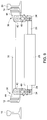
- FIG. 5 is another perspective view of the clip of FIG. 3 .
- FIG. 6 is a cross-sectional view of the clip of FIG. 3 .
- FIG. 7 is an enlarged, cross-sectional view of a clip-retaining mechanism of the clip of FIG. 3 .
- FIG. 8 is an enlarged, front, cross-sectional view of the switch point assembly of FIG. 2 , illustrating engagement of the clip with a point rail of the switch-point assembly.
- FIG. 9 is a front, cross-sectional view of the switch point assembly, illustrating normal operation.
- FIGS. 10 and 11 are front, cross-sectional views of the switch point assembly, illustrating a trailing operation.
- FIGS. 12-14 illustrate the clip of FIG. 3 during trailing operation, and show the corresponding positions of a clip retaining mechanism during such trailing operation.
- selectively coupled means that a component may be coupled to another component in one mode of operation, and decoupled with the another component in another mode of operation.
- a railway switch point assembly 10 includes two rail end points 12 , 14 .
- the rail end points 12 , 14 are tapered rail profiles capable of deflecting to move between two different positions in order to facilitate the correct alignment of the track components for the desired path of rolling stock transiting through the switch point assembly 10 .
- the switch point assembly 10 has two deflectable or movable rail end points 12 , 14 which move in concert with one another between first and second alternative positions. In a first alternative position, shown in FIG.
- a first one 12 of these movable rail end points 12 , 14 can be aligned with (e.g., positioned parallel to) a first fixed stock rail 16 to facilitate passage of the rolling stock straight through the switch point onto a first set of fixed rails 18 .
- the second movable rail end point 14 can be aligned with (e.g., positioned parallel to) a second fixed stock rail 20 to facilitate passage of the rolling stock onto a second set of fixed rails 22 .
- the two deflectable rail end points 12 , 14 are moved by rods 24 , 26 protruding from the opposite extremities of a unit called a switch point machine 28 (also referred to herein as a switch machine). Inside the switch point machine 28 , the rods 26 , 28 are usually connected to a device with a reciprocating straight line motion, which is powered by a motor unit which is generally placed to the side of the rails. In some configurations, a connecting rod or tie bar 30 may be utilized to tie the rail end points 12 , 14 rigidly to one another. As shown in FIG. 2 , a socket 34 is provided at the outer end of each rod 24 , 26 . Each rod socket 34 is pivotally connected to its associated rail end point 12 , 14 by a clip assembly 36 , as discussed in detail hereafter.
- eachclip assembly 36 includes a yoke 38 , a pivot pin 40 , a clip 42 , and a clamp block 44 .
- the yoke 38 extends substantially vertically from the socket 34 and includes a collar 46 having a horizontal bore centered on a horizontal axis 48 of the pivot pin 40 .
- the clip 42 is generally U-shaped and has a pair of opposed first and second depending legs 50 , 52 , each having a horizontal bore 54 therethrough centered on the horizontal axis 48 of the pivot pin 40 .
- the clip 42 and yoke 38 are, therefore, both configured to pivot about horizontal axis 48 when the pivot pin 40 is received by the bore of the collar 46 and the bores in the legs 50 , 52 of the clip 42 .
- the clip 42 also includes an upwardly extending third leg 56 having recesses 58 formed on opposing sides thereof, as best illustrated in FIG. 4 .
- the recesses 58 are sized to receive inserts 60 having an outwardly facing detent recess 62 .
- the inserts 60 may be secured within the recesses 58 of the clip 42 by screws or other suitable fasteners.
- the detent recesses may be formed in outward facing surfaces of the third leg 56 of the clip 42 (where the recesses 58 and inserts 60 may be omitted).
- the clamp block 44 includes a generally rectangular piece of stock having housing portion 64 protruding laterally from one side thereof.
- the housing portion 64 of the clamp block 44 includes a slot 66 formed therein that is sized and shaped to closely receive the third, upwardly extending leg 56 of the clip 42 .
- the opposed, lateral sides of the housing portion 64 include cylindrical recesses 68 that are configured to receive disc springs 70 therein, as discussed hereinafter.
- a ball aperture 72 located at the bottom of each recess 68 provides a passageway through the bottom wall of each recess 68 to the slot 66 .
- the ball apertures 72 are generally circular in shape.
- the recesses 68 are each configured to receive a respective spring-biased clip retaining mechanism 74 .
- the clip retaining mechanism 74 includes a t-shaped shaft 76 having a shaft portion 78 (see FIG. 7 ) and a disc-shaped head portion 80 .
- the head portion 80 is formed with a small depression 82 in the outer surface thereof opposite the shaft and centered axially about the longitudinal axis of the shaft 78 .
- the mechanism 74 also includes a detent ball 84 .
- the detent ball 84 is sized to be able to pass through ball apertures 72 at the bottom of the cylindrical recesses 68 and is located axially with respect to t-shaped shaft 76 by engagement with depression 82 .
- the mechanism 74 further includes disc springs 70 which may comprise a plurality of conical spring washers that are received on the shaft portion 78 of t-shaped shaft 76 , as well as a disc shaped adjustment plate 86 that is likewise received on the shaft portion 78 and which, in combination with the head portion 80 of the t-shaped shaft, sandwiches the disc springs 70 therebetween.
- Each clip retaining mechanism 74 is received fully within the respective recesses 68 in the housing 64 and is itself retained in place by flange plates 88 that may be secured to the housing with threaded bolts 90 or other suitable fasteners.
- FIG. 7 the arrangement of components of the clip retaining mechanism 74 is best illustrated.
- the detent balls 84 are positioned within the ball apertures 72 in the bottom of the recesses 68 and are held in place by the head portion 80 of the t-shaped shaft 76 .
- the disc springs 70 are received on shaft portion 78 of the shaft, along with adjustment plate 86 , and are held in place by flange plates 88 that are secured to the housing 64 of the camp 44 . As shown in FIG. 7 , the disc springs 70 bias the head portion 80 of the t-shaft 76 towards the bottom of the recess 68 .
- each clamp block 44 may be secured to the inside surface of a respective rail end point 12 , 14 via threaded bolts 92 .
- each clamp block 44 may be placed on a respective inside surface of one of the rail end points 12 , 14 and secured thereto by passing a threaded bolt 92 from an outwardly facing surface thereof through an aperture formed in the rail end point 12 , 14 such that the bolt 92 is received in a corresponding threaded bore (not shown) formed in the rear surface of the clamp block 44 .
- the clamp block 44 may include a pair of connecting blocks 94 that are mounted to the clamp block 44 via dowel pins 96 .
- the bolts 92 may be received by corresponding threaded bores formed in the rear side of the connecting blocks 94 .
- the connecting blocks 94 serve as a mounting means for the connecting rod 30 that spans the rail end points 12 , 14 and rigidly locks the end points together.
- the switch machine 28 is selectively operable to control the rail end points 12 , 14 between the first and second alternative positions to direct the rolling stock either straight through the switch point onto the first set of fixed rails 18 or to divert the rolling stock onto a second set of fixed rails 22 .
- the rods 26 , 28 of the switch machine 26 , 28 are selectively extendable to move the rail end points 12 , 14 between the first and second positions. As one of the rods 26 , 28 is extended, the outward pushing force from the rod is transmitted to the adjacent rail end point 12 , 14 through the clip assembly 36 .
- the clip 42 is configured to maintain a reliable and rigid connection to allow for movement of the rail end points 12 , 14 to the desired orientation.
- the disc springs 70 of the clip retaining mechanism 74 provide a large pre-setting compression force to provide the required rigidity of the entire switch point assembly 10 necessary to move and lock the rail end points 12 , 14 .
- the assembly 10 of embodiments of the invention offers the same functionality during facing-point movements as existing assemblies.
- the assembly 36 is configured to lock the rail end points 12 , 14 into location with high forces to minimize derailments.
- the wheels of the rolling stock may exert a lateral force on one of the rail end points 12 and urge the rail end point 12 away from its locked position.
- the trailing force exerted on rail end point 12 is represented by arrow A.
- this trailing force may damage the switch point machine and its components, especially in cases where the rail end points 12 , 14 are locked in position.
- Embodiments of the invention allow for the automatic decoupling of the switch point machine 28 from the rail end point 12 to which the trailing force A is exerted, thereby preventing damage to the switch point machine 28 and its components.
- the trailable clip 42 is configured to disengage from the slot 66 in the housing 64 to prevent the trailing force from being transferred to the switch point machine 28 and its components. This decoupling functionality is best illustrated in FIG. 11 .
- FIGS. 12-14 detail views of the clip assembly 36 and corresponding operation of the clip retaining mechanism 74 during a trailing-point movement are shown.
- clip 42 is retained in slot 66 by detent balls 84 that are urged into recesses 62 by the disc springs 70 of the clip retaining mechanism 74 .
- the clip 42 is clamped tightly from opposing sides by the disc springs 70 to retain the clip 42 in place.
- the clip 42 begins to rotate about the pivot pin 40 , as shown in the upper portion of FIG. 13 .
- the clamp block 44 begins to pull away from the clip 42 , causing the clip 42 to begin to slide out of the slot 66 , as illustrated in the lower portion of FIG. 13 .
- the detent balls 84 begin to climb the walls of the recesses 62 , which urges the detent balls 84 against the large spring bias of the disc springs 70 .
- the switch machine 28 may disengage from both rail end points 12 , 14 during trailing-point movements (upon application of a lateral trailing force A to one of the rail end points 12 , 14 ), as illustrated in FIG. 11 .
- the trailable clip assembly 36 is compact in design and is able to maintain a reliable and rigid connection between the switch machine and point rails under normal operation, while also being able to disconnect the switch machine from the point rail in trailing operation.
- the forces typically encountered during normal operation are not sufficient to cause the clip 42 to decouple from the clamp block 44 , as such forces are much less than those seen during trailing operation.
- the trailable clip 42 is, however, configured to reliably decouple when subjected to the much larger forces during trailing operation.
- the force at which the clip 42 disengages from the housing 64 rather than move in concert with the clamp block 44 is referred to herein as the threshold force.
- the threshold force value is at least 20,000 pounds (at least 88,000 newtons).
- the assembly maintains the integrity and functionality of the rail end points, the switch machine, and the rolling stock even after trailing-point movements
- the simplicity of the design of the trailable clip assembly 36 allows for quick and easy replacement in the field.
- the reduction in parts as compared to existing assemblies translates to a reduction in costs and an ease of replacement and servicing.
- An embodiment of the invention relates to an apparatus.
- the apparatus includes a clamp block configured for attachment to a rail end point, the clamp block including a housing having a slot formed therein, and a clip configured to be received in the slot.
- the clip is disengageable from the slot upon application of a generally lateral trailing force to the rail end point in excess of a threshold value.
- the clip is generally U-shaped and includes a pair of opposed depending legs each having an aperture formed therein adjacent to respective distal ends thereof for receiving a pivot pin, and an upwardly extending third leg. The third leg is configured to be received in the slot in the housing of the clamp block.
- the apparatus includes a clip retaining mechanism configured to retain the clip within the slot.
- the clip retaining mechanism may include at least one detent ball and a biasing mechanism configured to bias the at least one detent ball into engagement with a corresponding detent recess in the clip.
- the biasing mechanism is at least one disc spring.
- the clip retaining mechanism is positioned within the housing of the clamp block.
- the apparatus may include a second clip retaining mechanism configured to retain the clip within the slot. The second clip retaining mechanism is positioned within the housing on an opposing side of the clip from the clip retaining mechanism and includes at least one second detent ball and a second biasing mechanism configured to bias the at least one second detent ball into engagement with a corresponding second detent recess in the clip.
- the apparatus includes a connecting block engageable with the clamp block.
- the connecting block is configured to facilitate the attachment of a connecting rod between the clamp block and an opposing clamp block.
- the apparatus is configured to couple the rail end point to a switch machine.
- the clip is configured to maintain a rigid connection with the clamp block sufficient to transfer a pushing force from the switch machine to the rail end point, wherein the pushing force of the switch machine is below the threshold value.
- the assembly includes a first rail end point, a second rail end point, a switch machine configured to selectively move the first rail end point and second rail end point between first and second alternative positions, and a first clip assembly connecting a first end of the switch point machine to the first rail end point.
- the first clip assembly is configured to transmit a first pushing force from the switch machine to the first rail end point to move the first and second rail end points between the first and second alternative positions, and to automatically decouple the switch machine from the first rail end point during a trailing-point movement of a rolling vehicle.
- the assembly also includes a second clip assembly connecting a second end of the switch point machine to the second rail end point.
- the second clip assembly is configured to transmit a second pushing force from the switch machine to the second rail end point to move the first and second rail end points between the first and second alternative positions, and to automatically decouple the switch machine from the second rail end point during the trailing-point movement of the rolling vehicle.
- the first clip assembly and second clip assembly each include a clamp block configured for attachment to a respective one of the first and second rail end points, each clamp block including a housing having a slot formed therein, and a clip configured to be received in the slot. The clip is disengageable from the slot upon application of a generally lateral trailing force to one of the first and second rail end points during the trailing-point movement.
- each clip is generally U-shaped and includes a pair of opposed depending legs each having an aperture formed therein adjacent to respective distal ends thereof for receiving a pivot pin, and an upwardly extending third leg, wherein the third leg is configured to be received in the slot in the housing of the clamp block.
- the first and second clip assemblies may each include a clip retaining mechanism configured to retain the clip within the slot, the clip retaining mechanism including at least one detent ball and a biasing mechanism configured to bias the at least one detent ball into engagement with a corresponding detent recess in the clip.
- the biasing mechanism is at least one disc spring.
- first and second clip assemblies each include a connecting block engageable with each clamp block, the connecting blocks being configured to facilitate the attachment of a connecting rod between the first clip assembly and the second clip assembly.
- each clip is configured to maintain a rigid connection with the respective clamp block sufficient to transfer the pushing force from the switch machine to the first or second rail end point.
- Yet another embodiment of the invention relates to a method.
- the method includes the steps of connecting a first rail end point to a switch machine via a first clip assembly, the first clip assembly being configured to transmit a pushing force from the switch machine to the first rail end point to selectively move the first rail end point between first and second alternative positions, and during a trailing-point movement of a vehicle, automatically decoupling the switch machine from the first rail end point.
- the method may also include the steps of connecting a second rail end point to the switch machine via a second clip assembly, the second clip assembly being configured to transmit a second pushing force from the switch machine to the second rail end point to selectively move the second rail end point, and during the trailing-point movement of a vehicle, automatically decoupling the switch machine from the second rail end point.
- the first clip assembly and second clip assembly each include a clamp block configured for attachment to a respective one of the first and second rail end points, each clamp block including a housing having a slot formed therein, and a clip configured to be received in the slot. The clip is disengageable from the slot upon application of a generally lateral trailing force to one of the first and second rail end points during the trailing-point movement.
- each clip is generally U-shaped and includes a pair of opposed depending legs each having an aperture formed therein adjacent to respective distal ends thereof for receiving a pivot pin, and an upwardly extending third leg.
- the third leg is configured to be received in the slot in the housing of the clamp block.
- the first and second clip assemblies each include a clip retaining mechanism configured to retain the clip within the slot, the clip retaining mechanism including at least one detent ball and a biasing mechanism configured to bias the at least one detent ball into engagement with a corresponding detent recess in the clip.
Landscapes
- Engineering & Computer Science (AREA)
- Mechanical Engineering (AREA)
- Architecture (AREA)
- Civil Engineering (AREA)
- Structural Engineering (AREA)
- Train Traffic Observation, Control, And Security (AREA)
- Automobile Manufacture Line, Endless Track Vehicle, Trailer (AREA)
- Railway Tracks (AREA)
Abstract
Description
Claims (22)
Applications Claiming Priority (1)
| Application Number | Priority Date | Filing Date | Title |
|---|---|---|---|
| PCT/CN2015/076757 WO2016165109A1 (en) | 2015-04-16 | 2015-04-16 | Method and apparatus for switching device |
Publications (2)
| Publication Number | Publication Date |
|---|---|
| US20180087223A1 US20180087223A1 (en) | 2018-03-29 |
| US10697128B2 true US10697128B2 (en) | 2020-06-30 |
Family
ID=57126188
Family Applications (1)
| Application Number | Title | Priority Date | Filing Date |
|---|---|---|---|
| US15/566,519 Active 2036-02-13 US10697128B2 (en) | 2015-04-16 | 2015-04-16 | Method and apparatus for switching device |
Country Status (4)
| Country | Link |
|---|---|
| US (1) | US10697128B2 (en) |
| AU (1) | AU2015391064B2 (en) |
| CA (1) | CA2982619A1 (en) |
| WO (1) | WO2016165109A1 (en) |
Citations (5)
| Publication number | Priority date | Publication date | Assignee | Title |
|---|---|---|---|---|
| GB233285A (en) | 1925-02-17 | 1925-05-07 | Adam Young Storrar | Improved clamp for railway points or switches |
| EP0802102A1 (en) | 1996-04-17 | 1997-10-22 | CARL DAN. PEDDINGHAUS GMBH & CO. KG | Switch end lock |
| US5730395A (en) * | 1995-11-22 | 1998-03-24 | Gec Alsthom Transport Sa | Locking apparatus for locking a point of a rail switch, apparatus for operating and locking a point, a method of installing such apparatus, and apparatus for operating and locking a rail switch |
| CN2494378Y (en) | 2001-07-18 | 2002-06-05 | 耿修志 | Railway turnout without point rail switch |
| CN101870300A (en) | 2009-04-22 | 2010-10-27 | 施维哈克股份公司 | Switching devices in railway turnouts |
-
2015
- 2015-04-16 US US15/566,519 patent/US10697128B2/en active Active
- 2015-04-16 CA CA2982619A patent/CA2982619A1/en not_active Abandoned
- 2015-04-16 WO PCT/CN2015/076757 patent/WO2016165109A1/en not_active Ceased
- 2015-04-16 AU AU2015391064A patent/AU2015391064B2/en active Active
Patent Citations (5)
| Publication number | Priority date | Publication date | Assignee | Title |
|---|---|---|---|---|
| GB233285A (en) | 1925-02-17 | 1925-05-07 | Adam Young Storrar | Improved clamp for railway points or switches |
| US5730395A (en) * | 1995-11-22 | 1998-03-24 | Gec Alsthom Transport Sa | Locking apparatus for locking a point of a rail switch, apparatus for operating and locking a point, a method of installing such apparatus, and apparatus for operating and locking a rail switch |
| EP0802102A1 (en) | 1996-04-17 | 1997-10-22 | CARL DAN. PEDDINGHAUS GMBH & CO. KG | Switch end lock |
| CN2494378Y (en) | 2001-07-18 | 2002-06-05 | 耿修志 | Railway turnout without point rail switch |
| CN101870300A (en) | 2009-04-22 | 2010-10-27 | 施维哈克股份公司 | Switching devices in railway turnouts |
Non-Patent Citations (2)
| Title |
|---|
| International Search Report for PCT/CN2015/076757, dated Jan. 21, 2016. |
| Written Opinion of the International Searching Authority for PCT/CN2015/076757, completed Jan. 15, 2016. |
Also Published As
| Publication number | Publication date |
|---|---|
| CA2982619A1 (en) | 2016-10-20 |
| WO2016165109A1 (en) | 2016-10-20 |
| AU2015391064B2 (en) | 2021-01-14 |
| US20180087223A1 (en) | 2018-03-29 |
| AU2015391064A1 (en) | 2017-11-09 |
Similar Documents
| Publication | Publication Date | Title |
|---|---|---|
| CN101798890B (en) | Locking device | |
| US20090020655A1 (en) | Machine for railway switching | |
| CN116457263B (en) | Systems for automatically coupling and releasing vehicles traveling on a track network | |
| US4637579A (en) | Railroad switch mechanism | |
| US10697128B2 (en) | Method and apparatus for switching device | |
| US12539901B2 (en) | Reverse angled point slider | |
| EP3412535B1 (en) | Switching machine for a railroad | |
| CA2555727C (en) | Switch machine with switch point connectors | |
| AU2020355510A1 (en) | Articulation device for an articulated vehicle, corresponding vehicle and adjustment method | |
| US7341226B2 (en) | Movable point frog switching assembly | |
| US20210221519A1 (en) | Aircraft passenger seat leg anti-rattle with position restriction | |
| US8985526B2 (en) | Swivel point connector for railroad switches | |
| US5327605A (en) | Energy-absorbing span lock system for drawbridges | |
| US7191986B2 (en) | Device for mechanically and electrically checking the switching device of a railway switch machine | |
| CN204184368U (en) | For the fastening of the pitman of vertical support intermediate buffering unitor | |
| EP3617031A1 (en) | Railway train and electric motor suspension mechanism thereof | |
| WO2020240372A1 (en) | System for automatic coupling and release of vehicles travelling on the railway network | |
| EA046933B1 (en) | SYSTEM OF AUTOMATIC CLOSURE AND DISCOUPLEMENT OF ROLLING STOCK UNITS MOVEMENT ON THE RAILWAY NETWORK | |
| US10632036B2 (en) | Device for aligning and connecting a hood to a housing | |
| US20240025262A1 (en) | Locking device for a pantograph | |
| US6427951B1 (en) | Adjusting system for railroad turnout switch points |
Legal Events
| Date | Code | Title | Description |
|---|---|---|---|
| FEPP | Fee payment procedure |
Free format text: ENTITY STATUS SET TO UNDISCOUNTED (ORIGINAL EVENT CODE: BIG.); ENTITY STATUS OF PATENT OWNER: LARGE ENTITY |
|
| STPP | Information on status: patent application and granting procedure in general |
Free format text: DOCKETED NEW CASE - READY FOR EXAMINATION |
|
| AS | Assignment |
Owner name: GENERAL ELECTRIC COMPANY, NEW YORK Free format text: COMBINED DECLARATION AND ASSIGNMENT;ASSIGNOR:LI, BOSHENG;REEL/FRAME:045681/0604 Effective date: 20150506 |
|
| AS | Assignment |
Owner name: ALSTOM TRANSPORT TECHNOLOGIES, FRANCE Free format text: ASSIGNMENT OF ASSIGNORS INTEREST;ASSIGNOR:GENERAL ELECTRIC COMPANY;REEL/FRAME:045725/0371 Effective date: 20151102 |
|
| STPP | Information on status: patent application and granting procedure in general |
Free format text: NON FINAL ACTION MAILED |
|
| STPP | Information on status: patent application and granting procedure in general |
Free format text: RESPONSE TO NON-FINAL OFFICE ACTION ENTERED AND FORWARDED TO EXAMINER |
|
| STPP | Information on status: patent application and granting procedure in general |
Free format text: NOTICE OF ALLOWANCE MAILED -- APPLICATION RECEIVED IN OFFICE OF PUBLICATIONS |
|
| STCF | Information on status: patent grant |
Free format text: PATENTED CASE |
|
| MAFP | Maintenance fee payment |
Free format text: PAYMENT OF MAINTENANCE FEE, 4TH YEAR, LARGE ENTITY (ORIGINAL EVENT CODE: M1551); ENTITY STATUS OF PATENT OWNER: LARGE ENTITY Year of fee payment: 4 |