US1069706A - Machine for making ignition-strips. - Google Patents
Machine for making ignition-strips. Download PDFInfo
- Publication number
- US1069706A US1069706A US52940509A US1909529405A US1069706A US 1069706 A US1069706 A US 1069706A US 52940509 A US52940509 A US 52940509A US 1909529405 A US1909529405 A US 1909529405A US 1069706 A US1069706 A US 1069706A
- Authority
- US
- United States
- Prior art keywords
- frame
- rollers
- machine
- strips
- guides
- Prior art date
- Legal status (The legal status is an assumption and is not a legal conclusion. Google has not performed a legal analysis and makes no representation as to the accuracy of the status listed.)
- Expired - Lifetime
Links
Images
Classifications
-
- C—CHEMISTRY; METALLURGY
- C06—EXPLOSIVES; MATCHES
- C06F—MATCHES; MANUFACTURE OF MATCHES
- C06F1/00—Mechanical manufacture of matches
- C06F1/20—Applying strike-surfaces, e.g. on match-boxes on match-books
Definitions
- This invention relates to machines for applying to strips of suitable material, isolated spots of ignition material in order to produce What are commonly known as ignition strips such strips being employed in miners safety lamps.
- the object of the present invention is to provide an improved machine for rapidly and accurately applying the ignition material to a large number of strips which are temporarily supported by a frame or carrier in position to pass between two rollers which will apply the material simultaneously to two rows or series of lengths of the strip material.
- Special features of the invention relate to improved means for reciprocating the stripcarrying frame between the applying rollers.
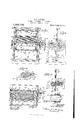
- Figure 1 is a front elevation of a machine embodying my present improvements
- Fig. 2 is an end view of the same, parts of the mechanism being broken away
- Fig. 3 represents a section on line AB of Fig. 1, portions of the frame being broken out to reduce the height of this figure
- Fig. 4 is a detail elevation from the left of Fig. 1
- Fig. 5 is a plan Viewof the machine with parts in section
- Fig. 6 is a detail sectional view of a portion of one of the applying rollers.
- Uprights a are mounted upon a suitable base a, and provide bearings for two applying rollers Z), 5', the roller I) being mounted in fixed bearings c, and the roller 6 being mounted in sliding bearings c.
- Suitably secured to the inner faces of the uprights a are two vertical rails or guides (Z, the inner faces of which are preferably angular or prismatic, as best shown in Fig. 5.
- the shaft-s of the two rollers Z), Z) are not in the same horizontal plane, but the shaft of the movable roller is, as shown, a little higher than that of the roller which is mounted in fixed bearings, this arrangement of the rolls enabling their applying rings to bear againstthe strips to be coated somewhat more closely than if'both rollers were at the same height.
- the tops of the rails or guides (Z are connected by a crossbar Z, while a lower crossbar Z connects the lower rails or guides.
- the guides e for the bearings c of roller Z) are provided with cavities c to receive projections c of a lever frame a.
- Said lever frame as best shown in Fig. 5, comprises a front bar having a handle a, the end portions of this lever frame embracing the shaft n of roll-er I).
- the vertical reciprocating frame comprises side bars 7, an upper crossbar g, and a lower crossbar g, the ends of the upper and lower crossbars fitting the beveled or inclined faces of the guide rails (1 so that the said frame can be slid up and down on said guide rails.
- Two ropes 72,, h are connected to the middle of the upper crossbar g, as by means of a suitable hook indicated at h and said ropes pass over pulleys 2', z mounted on the upper crossbar Z, and then over to the pulleys 70 at the tops of the guide rails (Z, the ends of said ropes being provided with weights m.
- a rope h is attached at one end to the lower crossbar g of the sliding frame leads under a guide pulley 1" carried by lower crossbar Z, then about a pulley 1" and up to a larger pulley 0 which is loosely mounted on the shaft 42, the rope being attached at one end to the said pulley 0.
- a disk p Keyed to the shaft a, close to the pulley 0, is a disk p in which is mounted a pin 9, which pin is spring-influenced to enable it to normally engage either one of a series of holes in the pulley o.
- a hand wheel 8 Secured to the end of shaft a is a hand wheel 8, while suitable gearing t connects the other ends of the two shafts n, n.
- the strip-carrier frame a may consist of four light strips connected at their corners, as best shown by Fig. 1, the side members being formed with recesses.
- This strip-carrier frame is temporarily mounted in the reciprocating frame and held there by suitable means as by means of suitable hooks 02 attached to the lower crossbar g.
- the upper crossbar 9 may have a hook m as best shown in Fig. 3, said hook having a ring connected as shown in Fig. 1.
- the movable applying roller 6 is moved away from the roller Z)
- the strip-carrier frame w may be inserted to position by simply engaging its lower horizontal member under the hooks a2 and slipping its upper horizontal member over the hooks 00 the latter being usually capable of yielding sufficiently to permit this to be done.
- a reverse operation permits the strip-carrier frame to be removed from the vertically reciprocating frame. Supported loosely on the shafts 12., 'n are two troughs or receptacles y for the ignition paste which is to be applied to the strips.
- each of the rollers b, 6 consists of a cylindrical portion 1 having end caps 2, rings 3 which are peripherally grooved being mounted on the cylindrical portions 1 and separated from each other by proper washers or distance-rings 4-
- the strip-carrier frame w while removed from the machine, has a long piece of narrow fabric or paper wound around it horizontally, as shown in Fig. 1, the stretches of the strip being held properly spaced by the notches or recesses in the side members of the frame 00. This of course results in each side of the frame w presenting a vertical series of stretches of strip material.
- the frame w is then engaged with the upper and lower members 9, g of the vertically reciprocating frame, as hereinbefore described, and the troughs g being filled or partially filled with ignition paste, the machine is ready to be operated.
- Turning the hand wheel 5 will pull down the reciprocating frame through the medium of the cord or rope h, and the applying rollers 71, b are rotated at the same time so that the peripherally grooved rings 3 carry paste materials from the troughs y up and press said material against the outer surfaces of the stretches of the strip ma terial supported by the carrier frame, so that the ignition material is applied to the strip material in separated patches, the degree of separation of the patches or spots being uniform in accordance with the spacing of the rings 3 of the applying rollers.
- the operator grasps the handle a and withdraws the roller 79, as has been described,
- the spring pin 7 is pulled outwardly so as to release the disk 0 from connection with the disk 7) and shaft a when the weights m may elevate the vertically reciprocating frame to its normal position. Release of the spring pin 9 will cause it to automatically rengage the pulley 0, so that when a new strip-carrying frame has been inserted in the vertically reciprocating frame, the machine is again ready for operation in the manner already described.
- I claim 1 In a machine of the character described, a pair of rollers having paste-applying disks, means for supplying paste to said disks, and a vertically movable open frame mounted in a plane between the two rollers to carry strips of flexible material between said rollers.
- a pair of rollers having paste-applying disks, means for supplying paste to said disks, and
- a vertically movable frame mounted in a .plane between the two rollers, one of said rollers being mounted in a plane higher than the other.
- one of said rollers being horizontally movmovable open frame mounted in a plane between the two rollers to carry strips of flexible material between said rollers, one of said rollers being mounted in a plane higher than the other.
- a machine of the character described comprising vertical guides, an open frame mounted to reciprocate in said guides and having means for normally holding it in elevated position, rollers having paste-applying means mounted on opposite sides of the plane of movement of said frame, and means for drawing said frame downwardly between said rollers.
- a machine of the character described comprising vertical guides, an open frame mounted to reciprocate in said guides and having means for normally holding it in elevated position, rollers having paste-applying means mounted on opposite sides of the plane of movement of said frame, and means for drawing said frame downwardly between said rollers, said means comprising a cord or rope connected to the frame, guide pulleys for said cord or rope, a shaft having a pulley to which said cord or rope is secured, and means for rotating said shaft.
- a machine of the character described comprising fixed uprights, guides supported thereby, an open frame vertically movable in said guides, a disk-carrying roller mounted in fixed bearings at one side of the said guides, another disk-carrying roller mounted in movable guides at the other side of said guides, means for adjusting the position of the last mentioned roller, and means for actuating the said vertically movable frame.
- a machine of the character described comprising a vertically open frame for supporting a stripcarrier, disk-carrying rollers. on opposite sides of said frame, means for simultaneously rotating said rollers in opposite directions, a pulley loosely mounted on the shaft of one of said rollers, a springpressed pin connected to said shaft to rotate therewith and adapted to engage said pulley, weights and connections for normally holding said frame elevated, and connections between the lower part of said frame and the said pulley, for lowering the frame when the pin is engaged with the pulley mentioned and the shaft carrying the same is rotated.
Landscapes
- Engineering & Computer Science (AREA)
- Manufacturing & Machinery (AREA)
- Mechanical Engineering (AREA)
- Chemical & Material Sciences (AREA)
- Organic Chemistry (AREA)
- Treatment Of Fiber Materials (AREA)
Description
B. F. KOEHLER. MACHINE FOR MAKING IGNITION STRIPS. APPLICATION FILED NOV. 22, 1909.
1,069,706. P n e g- 12,1913.
fia
" LUMBIA PLANOORAPH co. WASHINGTON, n c
UNTTED STATES PATENT QFFTCE.
ERNEST FELIX KOEHLER, OF HUDSON, MASSACHUSETTS, ASSIGNOR, BY MESNE ASSIGN- MENTS, TO E. H. KINGSBURY, AGENT, OF MAR-LBORO, MASSACHUSETTS.
MACHINE FOR MAKING IGNITION-STRIPS.
Specification of Letters Patent.
Patented Aug. 12,1913.
Application filed November 22, 1909. Serial No. 529,405.
To all whom it may concern:
Be it known that I, ERNEST FELIX KOEHLER, a subject of the Emperor of Germany, and formerly a resident of London, England, and now a resident of Hudson, in the county of Middlesex and Commonwealth of Massachusetts, have invented certain new and useful Improvements in Machines for Making Ignition-Strips, of which the following is a specification.
This invention relates to machines for applying to strips of suitable material, isolated spots of ignition material in order to produce What are commonly known as ignition strips such strips being employed in miners safety lamps.
The object of the present invention is to provide an improved machine for rapidly and accurately applying the ignition material to a large number of strips which are temporarily supported by a frame or carrier in position to pass between two rollers which will apply the material simultaneously to two rows or series of lengths of the strip material.
Special features of the invention relate to improved means for reciprocating the stripcarrying frame between the applying rollers.
To these ends the invention consists in the construction and combination of parts substantially as hereinafter described and claimed.
Of the accompanying drawings which form a part of this specification,Figure 1 is a front elevation of a machine embodying my present improvements; Fig. 2 is an end view of the same, parts of the mechanism being broken away; Fig. 3 represents a section on line AB of Fig. 1, portions of the frame being broken out to reduce the height of this figure; Fig. 4 is a detail elevation from the left of Fig. 1; Fig. 5 is a plan Viewof the machine with parts in section; and Fig. 6 is a detail sectional view of a portion of one of the applying rollers.
Similar reference characters indicate the same or similar parts in all the figures.
Uprights a are mounted upon a suitable base a, and provide bearings for two applying rollers Z), 5', the roller I) being mounted in fixed bearings c, and the roller 6 being mounted in sliding bearings c. Suitably secured to the inner faces of the uprights a are two vertical rails or guides (Z, the inner faces of which are preferably angular or prismatic, as best shown in Fig. 5. Preferably the shaft-s of the two rollers Z), Z) are not in the same horizontal plane, but the shaft of the movable roller is, as shown, a little higher than that of the roller which is mounted in fixed bearings, this arrangement of the rolls enabling their applying rings to bear againstthe strips to be coated somewhat more closely than if'both rollers were at the same height.
As shown in Fig. 1, the tops of the rails or guides (Z are connected by a crossbar Z, while a lower crossbar Z connects the lower rails or guides. The guides e for the bearings c of roller Z) are provided with cavities c to receive projections c of a lever frame a. Said lever frame, as best shown in Fig. 5, comprises a front bar having a handle a, the end portions of this lever frame embracing the shaft n of roll-er I). By grasping the handle a and lifting the lever frame so as to raise the projections 6 out of the cavities c, the shaft a and the roller Z) can be drawn away from the roller Z) and its shaft n and held in such removed position by dropping the projections c into other cavities c. This enables the stripcarrier frame to be placed in position and removed when desired.
The vertical reciprocating frame comprises side bars 7, an upper crossbar g, and a lower crossbar g, the ends of the upper and lower crossbars fitting the beveled or inclined faces of the guide rails (1 so that the said frame can be slid up and down on said guide rails. Two ropes 72,, h are connected to the middle of the upper crossbar g, as by means of a suitable hook indicated at h and said ropes pass over pulleys 2', z mounted on the upper crossbar Z, and then over to the pulleys 70 at the tops of the guide rails (Z, the ends of said ropes being provided with weights m. A rope h is attached at one end to the lower crossbar g of the sliding frame leads under a guide pulley 1" carried by lower crossbar Z, then about a pulley 1" and up to a larger pulley 0 which is loosely mounted on the shaft 42, the rope being attached at one end to the said pulley 0. Keyed to the shaft a, close to the pulley 0, is a disk p in which is mounted a pin 9, which pin is spring-influenced to enable it to normally engage either one of a series of holes in the pulley o.
Secured to the end of shaft a is a hand wheel 8, while suitable gearing t connects the other ends of the two shafts n, n.
The strip-carrier frame a: may consist of four light strips connected at their corners, as best shown by Fig. 1, the side members being formed with recesses. This strip-carrier frame is temporarily mounted in the reciprocating frame and held there by suitable means as by means of suitable hooks 02 attached to the lower crossbar g. The upper crossbar 9 may have a hook m as best shown in Fig. 3, said hook having a ring connected as shown in Fig. 1. Then the movable applying roller 6 is moved away from the roller Z), the strip-carrier frame w may be inserted to position by simply engaging its lower horizontal member under the hooks a2 and slipping its upper horizontal member over the hooks 00 the latter being usually capable of yielding sufficiently to permit this to be done. A reverse operation permits the strip-carrier frame to be removed from the vertically reciprocating frame. Supported loosely on the shafts 12., 'n are two troughs or receptacles y for the ignition paste which is to be applied to the strips.
As best shown in Fig. 6, each of the rollers b, 6 consists of a cylindrical portion 1 having end caps 2, rings 3 which are peripherally grooved being mounted on the cylindrical portions 1 and separated from each other by proper washers or distance-rings 4- In operation, the strip-carrier frame w, while removed from the machine, has a long piece of narrow fabric or paper wound around it horizontally, as shown in Fig. 1, the stretches of the strip being held properly spaced by the notches or recesses in the side members of the frame 00. This of course results in each side of the frame w presenting a vertical series of stretches of strip material. The frame w is then engaged with the upper and lower members 9, g of the vertically reciprocating frame, as hereinbefore described, and the troughs g being filled or partially filled with ignition paste, the machine is ready to be operated. Turning the hand wheel 5 will pull down the reciprocating frame through the medium of the cord or rope h, and the applying rollers 71, b are rotated at the same time so that the peripherally grooved rings 3 carry paste materials from the troughs y up and press said material against the outer surfaces of the stretches of the strip ma terial supported by the carrier frame, so that the ignition material is applied to the strip material in separated patches, the degree of separation of the patches or spots being uniform in accordance with the spacing of the rings 3 of the applying rollers. After the ignition material has been applied, the operator grasps the handle a and withdraws the roller 79, as has been described,
then the spring pin 7 is pulled outwardly so as to release the disk 0 from connection with the disk 7) and shaft a when the weights m may elevate the vertically reciprocating frame to its normal position. Release of the spring pin 9 will cause it to automatically rengage the pulley 0, so that when a new strip-carrying frame has been inserted in the vertically reciprocating frame, the machine is again ready for operation in the manner already described.
I claim 1. In a machine of the character described, a pair of rollers having paste-applying disks, means for supplying paste to said disks, and a vertically movable open frame mounted in a plane between the two rollers to carry strips of flexible material between said rollers.
2. In a machine of the character described, a pair of rollers having paste-applying disks, means for supplying paste to said disks, and
a vertically movable frame mounted in a .plane between the two rollers, one of said rollers being mounted in a plane higher than the other.
3. In a machine of the character described,
a pair of rollers having paste-applying disks,
one of said rollers being horizontally movmovable open frame mounted in a plane between the two rollers to carry strips of flexible material between said rollers, one of said rollers being mounted in a plane higher than the other.
l. A machine of the character described comprising vertical guides, an open frame mounted to reciprocate in said guides and having means for normally holding it in elevated position, rollers having paste-applying means mounted on opposite sides of the plane of movement of said frame, and means for drawing said frame downwardly between said rollers.
5. A machine of the character described comprising vertical guides, an open frame mounted to reciprocate in said guides and having means for normally holding it in elevated position, rollers having paste-applying means mounted on opposite sides of the plane of movement of said frame, and means for drawing said frame downwardly between said rollers, said means comprising a cord or rope connected to the frame, guide pulleys for said cord or rope, a shaft having a pulley to which said cord or rope is secured, and means for rotating said shaft.
6. A machine of the character described comprising fixed uprights, guides supported thereby, an open frame vertically movable in said guides, a disk-carrying roller mounted in fixed bearings at one side of the said guides, another disk-carrying roller mounted in movable guides at the other side of said guides, means for adjusting the position of the last mentioned roller, and means for actuating the said vertically movable frame.
7. A machine of the character described comprising a vertically open frame for supporting a stripcarrier, disk-carrying rollers. on opposite sides of said frame, means for simultaneously rotating said rollers in opposite directions, a pulley loosely mounted on the shaft of one of said rollers, a springpressed pin connected to said shaft to rotate therewith and adapted to engage said pulley, weights and connections for normally holding said frame elevated, and connections between the lower part of said frame and the said pulley, for lowering the frame when the pin is engaged with the pulley mentioned and the shaft carrying the same is rotated.
In testimony whereof I have hereunto set my hand in the presence of two subscribing witnesses.
ERNEST FELIX KOEHLER.
Witnesses:
H. E. TUR'roN, L. MAGNUS.
Copies of this patent may be obtained for five cents each, by addressing the Commissioner of Patents, Washington, D. G.
Priority Applications (1)
| Application Number | Priority Date | Filing Date | Title |
|---|---|---|---|
| US52940509A US1069706A (en) | 1909-11-22 | 1909-11-22 | Machine for making ignition-strips. |
Applications Claiming Priority (1)
| Application Number | Priority Date | Filing Date | Title |
|---|---|---|---|
| US52940509A US1069706A (en) | 1909-11-22 | 1909-11-22 | Machine for making ignition-strips. |
Publications (1)
| Publication Number | Publication Date |
|---|---|
| US1069706A true US1069706A (en) | 1913-08-12 |
Family
ID=3137943
Family Applications (1)
| Application Number | Title | Priority Date | Filing Date |
|---|---|---|---|
| US52940509A Expired - Lifetime US1069706A (en) | 1909-11-22 | 1909-11-22 | Machine for making ignition-strips. |
Country Status (1)
| Country | Link |
|---|---|
| US (1) | US1069706A (en) |
-
1909
- 1909-11-22 US US52940509A patent/US1069706A/en not_active Expired - Lifetime
Similar Documents
| Publication | Publication Date | Title |
|---|---|---|
| US1069706A (en) | Machine for making ignition-strips. | |
| US1029544A (en) | Fabric-marking machine. | |
| US1499307A (en) | Feeding and winding machine | |
| US220995A (en) | Improvement in barrel-holding clamps | |
| US3331135A (en) | Machine for marking garments for positioning buttons and buttonholes | |
| US518112A (en) | Machine for making shoes or covers for pneumatic tires | |
| US1014819A (en) | Machine for use in sorting veneer. | |
| US991412A (en) | Compressing-machine. | |
| US1255123A (en) | Tearing-machine. | |
| US793396A (en) | Bag printing and numbering machine. | |
| US2431123A (en) | Reciprocable double buck laundry press | |
| US471561A (en) | marchetti | |
| US580124A (en) | Apparatus for dyeing | |
| US712510A (en) | Stretching apparatus. | |
| US569453A (en) | Apparatus for dyeing skeins | |
| US949786A (en) | Branding-machine. | |
| US3107871A (en) | Pile fabric packing machine | |
| US1288748A (en) | Device for rolling strips of material. | |
| US801889A (en) | Woodworking-machine. | |
| US928202A (en) | Drying-machine. | |
| US1223894A (en) | Machine for making laminated soles. | |
| US972060A (en) | Apparatus for smoothing hanks of textile materials. | |
| US1557441A (en) | Pie rimming and pinching machine | |
| US680525A (en) | Drop-hammer. | |
| US2222590A (en) | Bead rolling machine |