US1069641A - Rotary engine. - Google Patents
Rotary engine. Download PDFInfo
- Publication number
- US1069641A US1069641A US43947108A US1908439471A US1069641A US 1069641 A US1069641 A US 1069641A US 43947108 A US43947108 A US 43947108A US 1908439471 A US1908439471 A US 1908439471A US 1069641 A US1069641 A US 1069641A
- Authority
- US
- United States
- Prior art keywords
- steam
- exhaust
- casing
- valve
- piston
- Prior art date
- Legal status (The legal status is an assumption and is not a legal conclusion. Google has not performed a legal analysis and makes no representation as to the accuracy of the status listed.)
- Expired - Lifetime
Links
Images


Classifications
-
- F—MECHANICAL ENGINEERING; LIGHTING; HEATING; WEAPONS; BLASTING
- F01—MACHINES OR ENGINES IN GENERAL; ENGINE PLANTS IN GENERAL; STEAM ENGINES
- F01C—ROTARY-PISTON OR OSCILLATING-PISTON MACHINES OR ENGINES
- F01C3/00—Rotary-piston machines or engines with non-parallel axes of movement of co-operating members
- F01C3/02—Rotary-piston machines or engines with non-parallel axes of movement of co-operating members the axes being arranged at an angle of 90 degrees
Definitions
- This invention relates to rotary engines of the type in which there is provided a rotor or rotor unit to form two annular steam spaces one beside the other, and a piston or pistons mounted on the rotor which on its rotation moves laterally from one annular space to the other, thus alternately acting as a piston or pistons in the respective laterally disposed annular spaces.
- the rotor takes the form of a disk medially disposed between the cover plates of the casing, so that thus two annular spaces are formed by the one disk, and, where one rotor unit alone is in question, by the cover plate of the casing.
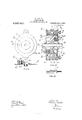
- Figure 1 is a diagrammatic transverse section of a motor provided according to the invention.
- Fig. 2 is a diagrammatic front sectional view corresponding to Fig. 1 and is a section through the steam belt.
- Fig. 3 is a diagrammatic view showing the section of top and bottom valves, the section being taken through the center line of the exhaust belt and also showing a portion of said exhaust belt.
- Fig. 4 is a detail front view of the rotor disk showing the steam and exhaust passages in broken lines and showing the sliding piston in position.
- Fig. 5 is a side elevation corresponding to Fig. 4:.
- Fig. 6 is a section taken through the line :0, m, Fig. at. Fig.
- Fig. 7 is a front elevation of the rotary engine.
- Fig. 8 is a side elevation corresponding to Fig. 7.
- Fig. 9 is a side elevation of the left hand cover plate of the engine casing showing the inclined face of the abutment; the right hand cover having a corresponding inclined face provided on it.
- Fig. 10 is an inside detail View corresponding to Fig. 9.
- Fig. 11 is a section, taken on the line '1, y, Fig. 10, showing the spring abutment.
- Fig. 12 is a transverse section of the rotary engine provided according to the invention showing the piston Specification of Letters Patent.
- Fig. 13 is a detail view in elevation of the circular valve provided at the top of the casing.
- I provide a cylindrical casing a having a combined inlet and exhaust valve casing preferably formed at the top thereof.
- This valve case Z) contains a circular valve 0 (Figs. 1, 2, 3 and 13) consisting of a hollow cylindrical body provided with steam inlets and outlets and with two arches disposed at opposite ends on opposite sides, to form, with the valve casing, exhaust passages.
- a circular valve 0 Figs. 1, 2, 3 and 13
- Fig. 1 Figs. 1, 2, 3 and 13
- the valve 0 as shown diagrammatically in. Fig. 3 shows the section thereof through the exhaust belt 6. This valve 0 is turned upside down when it is required to reverse the engine.
- the combined inlet and exhaust valve 0 serves to control the admission and exhaust of steam from the respective channels or steam belts (Z and e which extend circumferentially around the rotating disk f, it being understood that these channels (Z and e are formed integral with the casing a.
- the belt d serves for the reception of steam from the steam inlet 3 and the belt 6 for receiving the exhaust which escapes from the exhaust outlet 9.
- the rotating disk f which is keyed on the driving shaft f is provided with annular spaces 9 g extending circumferentially around the rotor disk and on each side thereof, within both of which protrude abutments h and 2' (shown diagrammatically in Fig. 2 and in section in Figs. 11 and 12).
- the abutment h protrudes from and is formed integral with the left hand casing cover and the abutment 2' is similarly provided on the right hand cover k.
- These abutments are formed with correspondingly inclined faces which protrude into the respective annular spaces 9 9 until at the positions indicated at h and 2" (Fig. 2) the respective abutments come into contact with each face of the rotor disk f.
- spring abutments or contact segments h 2" which are placed in recesses b 71 provided in the respective abutment guides and these contact segments or abutments h z" are kept in close contact with the rotor disk f and thus form steam tight contacts at these places by means of springs 72, i or by any other suitable means and guide rods 72 Z are provided on which the springs 71? i are mounted as shown in Figs. 11 and 12.
- the piston Z is of a width slightly more than that of the annular spaces g g and it will be understood that the piston Z slides within a slot f" formed in the rotor disk f (Fig. 12) and in a parallel direction to the axis of rotation of the disk which has grooves formed in the walls thereof.
- the piston Z is therefore constrained to move from one annular space, 9 tqthe other g during its rotation withthe disk f and has therefore co'm'pound motion, constituted of rotary and a reciprocating movement.
- the piston Z is preferably laminated or constituted of z a number of plates as shown diagrammatically,
- the rotor disk f is provided with channels or passages and ports therein, the passages m and a being placed in the middle wall of the rotor disk and passages, m a, placed around the periphery of the diskj' as shown.
- the passages m and W2) are for steam respectively onthe one side of'the piston Z, and n and n for exhaust respectively on the other side of the piston.
- the passages m and m are in alinement with the steam belt OZ, 5. (2., they are both on the left hand side of the rotor disk and communicate with the steam inlet 8 on the top of the casing a or the exhaust port q according as the rotor disk is rotating forward or backward.
- the passages 11 and n are both on the right hand side of the rotor disk and communicate with the, exhaust outlet (1 and the steam inlet 3 according to the direction'of rotation of tl1e'roto-r disk.
- the passage on communicates with a steam port 0 leading into the 'annularspace g and the passage m with a corresponding port on the other side of the rotor disk leading into the annular space g, while the passage n communicates with an exhaust port 79 leading into the annular space 9 and the passage n with a Corresponding port lead ing into the annular space 9.
- a steam port 0 and exhaust port 0 are provided on each side of the rotor disk wall.
- the length ofthe passages is so arranged that the steam passage m comes adjacent to or passes the barrier or bar a at the top of the casing at the same time that the piston Z comes adjacent to or passes the abutmentseg'ment, z"; and the steam passage m comes adjacent to or passes the bar a at the same time that the piston Z comes adjacent to or passes the abutment segment it.
- the rotary valve 7" is provided with two ports 1" and 7 arranged transversely to one another, the port r being in alinement with the steam belt (Z on the left hand side and the port 1" in alinement with the exhaust belt 6 on the right hand'side.
- This valve 1' is geared in any suitable manner with the combined inlet and exhaust valve 0.
- the r0- tor disk is advantageously provided with piston rings f (Fig. 12) disposed in position on the enter sides of the steam and exhaust belts (Z 6 so as to secure a steam tight joint with the asing a;
- the steam enters through the inlet 8 formed integral with the valve casing Z) and from the valve 0 as re resented in Fi 2 which is a section through the steam belt, enters the steam belt or channel (Z and goes half Way around the casing, being intercepted by the bottom valve 9" and also the barrier or bar a cast integrally with and adjacent to the casing of the top valve 6.
- the steam then enters the passage m and passes through the port 0 into the annular space 9' and drives the piston Z downward toward the valve 1", acting on the piston during the rotation of the rotor disk and then, passing out through the exhaust passage n to the exhaust belt 6, finally escapes through the exhaust outlet q.
- the passage m passes the a bar (4 and thus becomes open to steam while the passage m passes the bar (L so that steam is. no longer admitted'to the annular space 9'. Steam now enters by the passage m, passingto the annular space 9 where it acts upon the piston Z during the rotation of the disk f and then passes out by the exhaust passage n, the exhaust belt a, and the exhaust outlet 9.
- valve 0 For driving in the reverse direction the valve 0 is turned through half a revolution so as to bring the steam inlet 8 into communication with the belt'e, and the exhaust port q into communication with the belt (Z while, at the same time, the valve 1" is rotated so that the passage 7' is thrown open and'the passage 1' is closed.
- a rotary engine comprising a rotor casing, said casing having two steam belts passing around its inner periphery, avalve casing integral with said rotor casing, a combined inlet and exhaust valve Within said valve casing, a second valve disposed in the rotor casing diametrically opposite said combined inlet and exhaust valve, a shaft, a rotor mounted on said shaft, a laterally movable piston Within said rotor, said rotor having two steam passages communicating respectively one With the front side of the piston and the other With the rear of the piston and With the steam belts in the rotor casing, lateral covers in said rotor casing and abutments on said lateral covers, and spring portions in said abutments, said spring portions consisting of segments, a guide rod connected to each of said segments, and springs between the segments and lateral covers.
Description
W. FISHER.
ROTARY ENGINE.
APPLICATION FILED JUNE 19 Patented Aug. 5, 1913.
3 SHEBTS'SHEET l cmmmnm vmmmlmvu c1. WASHINGTON. n. cy
W. FISHER.
ROTARY ENGINE.
APPLICATION FILED JUNE 19, 1908.
Patented Aug". 5, 1913.
2 a SHEETSSHEET 2. f 1?) f 7 f ct; L
coLuMmA PLANomz/mu CO..\VASH|NGTON, i). c.
W. FISHER.
ROTARY ENGINE.
APPLICATION FILED JUNE 19, 1908.
1,069,641 Patented Aug. 5, 1913.
3 SHBETSSHEET a. 5 5
WILLIAM FISHER, OF NORTH TAWTON, ENGLAND.
ROTARY ENGINE.
To all whom it may concern:
Be it known that I, \VILLIAM FISHER, a subject of the King of Great Britain and Ireland, residing at North Tawton, Devonshire, England, (whose post-office address is North Tawton, Devonshire, England) have invented certain new and useful Improvements in and Relating to Rotary Engines, of which the following is a specification.
This invention relates to rotary engines of the type in which there is provided a rotor or rotor unit to form two annular steam spaces one beside the other, and a piston or pistons mounted on the rotor which on its rotation moves laterally from one annular space to the other, thus alternately acting as a piston or pistons in the respective laterally disposed annular spaces. The rotor takes the form of a disk medially disposed between the cover plates of the casing, so that thus two annular spaces are formed by the one disk, and, where one rotor unit alone is in question, by the cover plate of the casing.
The invention is illustrated in the accompanying drawings in which Figure 1 is a diagrammatic transverse section of a motor provided according to the invention. Fig. 2 is a diagrammatic front sectional view corresponding to Fig. 1 and is a section through the steam belt. Fig. 3 is a diagrammatic view showing the section of top and bottom valves, the section being taken through the center line of the exhaust belt and also showing a portion of said exhaust belt. Fig. 4 is a detail front view of the rotor disk showing the steam and exhaust passages in broken lines and showing the sliding piston in position. Fig. 5 is a side elevation corresponding to Fig. 4:. Fig. 6 is a section taken through the line :0, m, Fig. at. Fig. 7 is a front elevation of the rotary engine. Fig. 8 is a side elevation corresponding to Fig. 7. Fig. 9 is a side elevation of the left hand cover plate of the engine casing showing the inclined face of the abutment; the right hand cover having a corresponding inclined face provided on it. Fig. 10 is an inside detail View corresponding to Fig. 9. Fig. 11 is a section, taken on the line '1, y, Fig. 10, showing the spring abutment. Fig. 12 is a transverse section of the rotary engine provided according to the invention showing the piston Specification of Letters Patent.
Application filed June 19, 1908.
Patented Aug. 5,1913.
Serial No. 439,471.
at its lowest position. Fig. 13 is a detail view in elevation of the circular valve provided at the top of the casing.
As illustrated in the accompanying drawings, I provide a cylindrical casing a having a combined inlet and exhaust valve casing preferably formed at the top thereof. This valve case Z) contains a circular valve 0 (Figs. 1, 2, 3 and 13) consisting of a hollow cylindrical body provided with steam inlets and outlets and with two arches disposed at opposite ends on opposite sides, to form, with the valve casing, exhaust passages. When in the position shown in Fig. 2 it serves to admit steam into the casing a for forward driving e. in the direction shown by the arrow in Fig. 2). The valve 0 as shown diagrammatically in. Fig. 3 shows the section thereof through the exhaust belt 6. This valve 0 is turned upside down when it is required to reverse the engine.
The combined inlet and exhaust valve 0 serves to control the admission and exhaust of steam from the respective channels or steam belts (Z and e which extend circumferentially around the rotating disk f, it being understood that these channels (Z and e are formed integral with the casing a. For forward driving the belt d serves for the reception of steam from the steam inlet 3 and the belt 6 for receiving the exhaust which escapes from the exhaust outlet 9. The rotating disk f which is keyed on the driving shaft f is provided with annular spaces 9 g extending circumferentially around the rotor disk and on each side thereof, within both of which protrude abutments h and 2' (shown diagrammatically in Fig. 2 and in section in Figs. 11 and 12).
The abutment h protrudes from and is formed integral with the left hand casing cover and the abutment 2' is similarly provided on the right hand cover k. These abutments are formed with correspondingly inclined faces which protrude into the respective annular spaces 9 9 until at the positions indicated at h and 2" (Fig. 2) the respective abutments come into contact with each face of the rotor disk f. At these contact positions there are provided spring abutments or contact segments h 2" which are placed in recesses b 71 provided in the respective abutment guides and these contact segments or abutments h z" are kept in close contact with the rotor disk f and thus form steam tight contacts at these places by means of springs 72, i or by any other suitable means and guide rods 72 Z are provided on which the springs 71? i are mounted as shown in Figs. 11 and 12.
The piston Z is of a width slightly more than that of the annular spaces g g and it will be understood that the piston Z slides within a slot f" formed in the rotor disk f (Fig. 12) and in a parallel direction to the axis of rotation of the disk which has grooves formed in the walls thereof. The piston Z is therefore constrained to move from one annular space, 9 tqthe other g during its rotation withthe disk f and has therefore co'm'pound motion, constituted of rotary and a reciprocating movement. The piston Z is preferably laminated or constituted of z a number of plates as shown diagrammatically,
Referring to the diagrammatic views Figs. 1 and 2, the rotor disk f is provided with channels or passages and ports therein, the passages m and a being placed in the middle wall of the rotor disk and passages, m a, placed around the periphery of the diskj' as shown. The passages m and W2) are for steam respectively onthe one side of'the piston Z, and n and n for exhaust respectively on the other side of the piston. The passages m and m are in alinement with the steam belt OZ, 5. (2., they are both on the left hand side of the rotor disk and communicate with the steam inlet 8 on the top of the casing a or the exhaust port q according as the rotor disk is rotating forward or backward. In like manner: the passages 11 and n are both on the right hand side of the rotor disk and communicate with the, exhaust outlet (1 and the steam inlet 3 according to the direction'of rotation of tl1e'roto-r disk.
The passage on communicates with a steam port 0 leading into the 'annularspace g and the passage m with a corresponding port on the other side of the rotor disk leading into the annular space g, while the passage n communicates with an exhaust port 79 leading into the annular space 9 and the passage n with a Corresponding port lead ing into the annular space 9. Thus a steam port 0 and exhaust port 0 are provided on each side of the rotor disk wall. The length ofthe passages is so arranged that the steam passage m comes adjacent to or passes the barrier or bar a at the top of the casing at the same time that the piston Z comes adjacent to or passes the abutmentseg'ment, z"; and the steam passage m comes adjacent to or passes the bar a at the same time that the piston Z comes adjacent to or passes the abutment segment it.
After the piston Z has passed the spring abutment z" steam is admitted and acts against the piston through the passage m while the exhaust steam in front of the piston escapes through the passage 17/ and the exhaust outlet 1, the valves 0 and 1" being in the position indicated diagrammatically in Figs. 2 and 8.
The rotary valve 7" is provided with two ports 1" and 7 arranged transversely to one another, the port r being in alinement with the steam belt (Z on the left hand side and the port 1" in alinement with the exhaust belt 6 on the right hand'side. This valve 1' is geared in any suitable manner with the combined inlet and exhaust valve 0. The r0- tor disk is advantageously provided with piston rings f (Fig. 12) disposed in position on the enter sides of the steam and exhaust belts (Z 6 so as to secure a steam tight joint with the asing a;
As shown in Figs. 2 and 3 the steam belt or passage (Z is closed at a by a barrier or projection on the left hand side of the valve 6 and the'exhaust belt or passage 6 is closed' at on the right hand side, while at the bottom of the casing both belts or passages are closed by barrier formed integral with the casing a the only communication for steam being through the valve ports r and r 7 The operation of the engine for forward drivingis as follows :-The top valve 6 being in the position shown in Figs. 1, 2 and 3 the steam enters through the inlet 8 formed integral with the valve casing Z) and from the valve 0 as re resented in Fi 2 which is a section through the steam belt, enters the steam belt or channel (Z and goes half Way around the casing, being intercepted by the bottom valve 9" and also the barrier or bar a cast integrally with and adjacent to the casing of the top valve 6. The steam then enters the passage m and passes through the port 0 into the annular space 9' and drives the piston Z downward toward the valve 1", acting on the piston during the rotation of the rotor disk and then, passing out through the exhaust passage n to the exhaust belt 6, finally escapes through the exhaust outlet q. At the moment the piston passes the abutment segment h, the passage m, passes the a bar (4 and thus becomes open to steam while the passage m passes the bar (L so that steam is. no longer admitted'to the annular space 9'. Steam now enters by the passage m, passingto the annular space 9 where it acts upon the piston Z during the rotation of the disk f and then passes out by the exhaust passage n, the exhaust belt a, and the exhaust outlet 9. For driving in the reverse direction the valve 0 is turned through half a revolution so as to bring the steam inlet 8 into communication with the belt'e, and the exhaust port q into communication with the belt (Z while, at the same time, the valve 1" is rotated so that the passage 7' is thrown open and'the passage 1' is closed.
l/Vhat I claim as my invention and desire to secure by Letters Patent is A rotary engine comprising a rotor casing, said casing having two steam belts passing around its inner periphery, avalve casing integral with said rotor casing, a combined inlet and exhaust valve Within said valve casing, a second valve disposed in the rotor casing diametrically opposite said combined inlet and exhaust valve, a shaft, a rotor mounted on said shaft, a laterally movable piston Within said rotor, said rotor having two steam passages communicating respectively one With the front side of the piston and the other With the rear of the piston and With the steam belts in the rotor casing, lateral covers in said rotor casing and abutments on said lateral covers, and spring portions in said abutments, said spring portions consisting of segments, a guide rod connected to each of said segments, and springs between the segments and lateral covers.
In testimony whereof I have hereunto signed my name to this specification in the presence of tWo subscribing Witnesses.
WILLIAM FISHER.
IVitnesses FRANCIS IVRIGHT, A. E. BEDFORD.
Copies of this patent may be obtained for five cents each, by addressing the Commissioner of Patents, Washington, .D. C.
Priority Applications (1)
| Application Number | Priority Date | Filing Date | Title |
|---|---|---|---|
| US43947108A US1069641A (en) | 1908-06-19 | 1908-06-19 | Rotary engine. |
Applications Claiming Priority (1)
| Application Number | Priority Date | Filing Date | Title |
|---|---|---|---|
| US43947108A US1069641A (en) | 1908-06-19 | 1908-06-19 | Rotary engine. |
Publications (1)
| Publication Number | Publication Date |
|---|---|
| US1069641A true US1069641A (en) | 1913-08-05 |
Family
ID=3137878
Family Applications (1)
| Application Number | Title | Priority Date | Filing Date |
|---|---|---|---|
| US43947108A Expired - Lifetime US1069641A (en) | 1908-06-19 | 1908-06-19 | Rotary engine. |
Country Status (1)
| Country | Link |
|---|---|
| US (1) | US1069641A (en) |
-
1908
- 1908-06-19 US US43947108A patent/US1069641A/en not_active Expired - Lifetime
Similar Documents
| Publication | Publication Date | Title |
|---|---|---|
| US1069641A (en) | Rotary engine. | |
| US597793A (en) | Rotary engine | |
| US560252A (en) | Rotary engine | |
| US861164A (en) | Rotary engine. | |
| US802920A (en) | Rotary engine. | |
| US669000A (en) | Rotary engine. | |
| US1053767A (en) | Rotary engine. | |
| US633730A (en) | Rotary steam-engine. | |
| US395039A (en) | engine | |
| US389328A (en) | Rotary engine | |
| US774056A (en) | Rotary engine. | |
| US151532A (en) | Improvement in rotary engines | |
| US392356A (en) | Rotary steam-engine | |
| US230907A (en) | thibalt | |
| US444087A (en) | Pleau | |
| US287379A (en) | Rotary steam-engine | |
| US730489A (en) | Rotary engine. | |
| US818756A (en) | Rotary engine. | |
| US398512A (en) | And john h | |
| US627832A (en) | Rotary engine. | |
| US801891A (en) | Rotary engine. | |
| US467416A (en) | Rotary engine | |
| US764247A (en) | Rotary engine. | |
| US716143A (en) | Motor. | |
| US414359A (en) | akers |