US10695834B2 - Material feeder of additive manufacturing apparatus, additive manufacturing apparatus, and additive manufacturing method - Google Patents
Material feeder of additive manufacturing apparatus, additive manufacturing apparatus, and additive manufacturing method Download PDFInfo
- Publication number
- US10695834B2 US10695834B2 US15/124,270 US201415124270A US10695834B2 US 10695834 B2 US10695834 B2 US 10695834B2 US 201415124270 A US201415124270 A US 201415124270A US 10695834 B2 US10695834 B2 US 10695834B2
- Authority
- US
- United States
- Prior art keywords
- feed
- feeder
- region
- container
- material feeder
- Prior art date
- Legal status (The legal status is an assumption and is not a legal conclusion. Google has not performed a legal analysis and makes no representation as to the accuracy of the status listed.)
- Expired - Fee Related, expires
Links
Images


Classifications
-
- B—PERFORMING OPERATIONS; TRANSPORTING
- B29—WORKING OF PLASTICS; WORKING OF SUBSTANCES IN A PLASTIC STATE IN GENERAL
- B29C—SHAPING OR JOINING OF PLASTICS; SHAPING OF MATERIAL IN A PLASTIC STATE, NOT OTHERWISE PROVIDED FOR; AFTER-TREATMENT OF THE SHAPED PRODUCTS, e.g. REPAIRING
- B29C70/00—Shaping composites, i.e. plastics material comprising reinforcements, fillers or preformed parts, e.g. inserts
- B29C70/04—Shaping composites, i.e. plastics material comprising reinforcements, fillers or preformed parts, e.g. inserts comprising reinforcements only, e.g. self-reinforcing plastics
- B29C70/28—Shaping operations therefor
- B29C70/30—Shaping by lay-up, i.e. applying fibres, tape or broadsheet on a mould, former or core; Shaping by spray-up, i.e. spraying of fibres on a mould, former or core
- B29C70/38—Automated lay-up, e.g. using robots, laying filaments according to predetermined patterns
- B29C70/386—Automated tape laying [ATL]
-
- B22F3/1055—
-
- B—PERFORMING OPERATIONS; TRANSPORTING
- B22—CASTING; POWDER METALLURGY
- B22F—WORKING METALLIC POWDER; MANUFACTURE OF ARTICLES FROM METALLIC POWDER; MAKING METALLIC POWDER; APPARATUS OR DEVICES SPECIALLY ADAPTED FOR METALLIC POWDER
- B22F12/00—Apparatus or devices specially adapted for additive manufacturing; Auxiliary means for additive manufacturing; Combinations of additive manufacturing apparatus or devices with other processing apparatus or devices
- B22F12/50—Means for feeding of material, e.g. heads
-
- B—PERFORMING OPERATIONS; TRANSPORTING
- B22—CASTING; POWDER METALLURGY
- B22F—WORKING METALLIC POWDER; MANUFACTURE OF ARTICLES FROM METALLIC POWDER; MAKING METALLIC POWDER; APPARATUS OR DEVICES SPECIALLY ADAPTED FOR METALLIC POWDER
- B22F3/00—Manufacture of workpieces or articles from metallic powder characterised by the manner of compacting or sintering; Apparatus specially adapted therefor ; Presses and furnaces
- B22F3/004—Filling molds with powder
-
- B—PERFORMING OPERATIONS; TRANSPORTING
- B29—WORKING OF PLASTICS; WORKING OF SUBSTANCES IN A PLASTIC STATE IN GENERAL
- B29C—SHAPING OR JOINING OF PLASTICS; SHAPING OF MATERIAL IN A PLASTIC STATE, NOT OTHERWISE PROVIDED FOR; AFTER-TREATMENT OF THE SHAPED PRODUCTS, e.g. REPAIRING
- B29C64/00—Additive manufacturing, i.e. manufacturing of three-dimensional [3D] objects by additive deposition, additive agglomeration or additive layering, e.g. by 3D printing, stereolithography or selective laser sintering
- B29C64/10—Processes of additive manufacturing
- B29C64/141—Processes of additive manufacturing using only solid materials
- B29C64/153—Processes of additive manufacturing using only solid materials using layers of powder being selectively joined, e.g. by selective laser sintering or melting
-
- B—PERFORMING OPERATIONS; TRANSPORTING
- B33—ADDITIVE MANUFACTURING TECHNOLOGY
- B33Y—ADDITIVE MANUFACTURING, i.e. MANUFACTURING OF THREE-DIMENSIONAL [3D] OBJECTS BY ADDITIVE DEPOSITION, ADDITIVE AGGLOMERATION OR ADDITIVE LAYERING, e.g. BY 3D PRINTING, STEREOLITHOGRAPHY OR SELECTIVE LASER SINTERING
- B33Y30/00—Apparatus for additive manufacturing; Details thereof or accessories therefor
-
- B—PERFORMING OPERATIONS; TRANSPORTING
- B22—CASTING; POWDER METALLURGY
- B22F—WORKING METALLIC POWDER; MANUFACTURE OF ARTICLES FROM METALLIC POWDER; MAKING METALLIC POWDER; APPARATUS OR DEVICES SPECIALLY ADAPTED FOR METALLIC POWDER
- B22F10/00—Additive manufacturing of workpieces or articles from metallic powder
- B22F10/20—Direct sintering or melting
- B22F10/28—Powder bed fusion, e.g. selective laser melting [SLM] or electron beam melting [EBM]
-
- B—PERFORMING OPERATIONS; TRANSPORTING
- B22—CASTING; POWDER METALLURGY
- B22F—WORKING METALLIC POWDER; MANUFACTURE OF ARTICLES FROM METALLIC POWDER; MAKING METALLIC POWDER; APPARATUS OR DEVICES SPECIALLY ADAPTED FOR METALLIC POWDER
- B22F10/00—Additive manufacturing of workpieces or articles from metallic powder
- B22F10/30—Process control
- B22F10/32—Process control of the atmosphere, e.g. composition or pressure in a building chamber
-
- B—PERFORMING OPERATIONS; TRANSPORTING
- B22—CASTING; POWDER METALLURGY
- B22F—WORKING METALLIC POWDER; MANUFACTURE OF ARTICLES FROM METALLIC POWDER; MAKING METALLIC POWDER; APPARATUS OR DEVICES SPECIALLY ADAPTED FOR METALLIC POWDER
- B22F10/00—Additive manufacturing of workpieces or articles from metallic powder
- B22F10/30—Process control
- B22F10/36—Process control of energy beam parameters
-
- B—PERFORMING OPERATIONS; TRANSPORTING
- B22—CASTING; POWDER METALLURGY
- B22F—WORKING METALLIC POWDER; MANUFACTURE OF ARTICLES FROM METALLIC POWDER; MAKING METALLIC POWDER; APPARATUS OR DEVICES SPECIALLY ADAPTED FOR METALLIC POWDER
- B22F12/00—Apparatus or devices specially adapted for additive manufacturing; Auxiliary means for additive manufacturing; Combinations of additive manufacturing apparatus or devices with other processing apparatus or devices
- B22F12/40—Radiation means
- B22F12/44—Radiation means characterised by the configuration of the radiation means
-
- B—PERFORMING OPERATIONS; TRANSPORTING
- B22—CASTING; POWDER METALLURGY
- B22F—WORKING METALLIC POWDER; MANUFACTURE OF ARTICLES FROM METALLIC POWDER; MAKING METALLIC POWDER; APPARATUS OR DEVICES SPECIALLY ADAPTED FOR METALLIC POWDER
- B22F12/00—Apparatus or devices specially adapted for additive manufacturing; Auxiliary means for additive manufacturing; Combinations of additive manufacturing apparatus or devices with other processing apparatus or devices
- B22F12/40—Radiation means
- B22F12/49—Scanners
-
- B22F2003/1056—
-
- Y—GENERAL TAGGING OF NEW TECHNOLOGICAL DEVELOPMENTS; GENERAL TAGGING OF CROSS-SECTIONAL TECHNOLOGIES SPANNING OVER SEVERAL SECTIONS OF THE IPC; TECHNICAL SUBJECTS COVERED BY FORMER USPC CROSS-REFERENCE ART COLLECTIONS [XRACs] AND DIGESTS
- Y02—TECHNOLOGIES OR APPLICATIONS FOR MITIGATION OR ADAPTATION AGAINST CLIMATE CHANGE
- Y02P—CLIMATE CHANGE MITIGATION TECHNOLOGIES IN THE PRODUCTION OR PROCESSING OF GOODS
- Y02P10/00—Technologies related to metal processing
- Y02P10/25—Process efficiency
-
- Y02P10/295—
Definitions
- Embodiments described herein relate generally to material feeders of additive manufacturing apparatuses, additive manufacturing apparatuses, and additive manufacturing methods.
- additive manufacturing apparatuses such as three-dimensional printers. These three-dimensional printers form layers of a powdery material and solidify such a material for each layer of the material with binders (bonding agents) or laser beams to form three-dimensional shapes.
- Patent Literature 1 Japanese Patent Application Laid-open No. 2007-216595
- FIG. 1 is a schematic view of a three-dimensional printer according to a first embodiment.
- FIG. 2 is a sectional view of a stage and a material feeder at a feed position in a first embodiment.
- FIG. 3 is a perspective view of the stage and the material feeder at the feed position in the first embodiment.
- FIG. 4 is a sectional view of the stage and the material feeder with a closure wall being at a closing position in the first embodiment.
- FIG. 5 is a sectional view of the stage with a manufactured object being formed in the first embodiment.
- FIG. 6 is a perspective view of the stage and the material feeder at the feed position according to a second embodiment.
- FIG. 7 is a sectional view of the stage and the material feeder with the closure plate being at the closing position in the second embodiment.
- FIG. 8 is a sectional view of the stage and the material feeder according to a third embodiment.
- FIG. 9 is a sectional view of the stage and the material feeder with a piston being at a closing position in the third embodiment.
- FIG. 10 is a sectional view of the stage and the material feeder according to a fourth embodiment.
- FIG. 11 is a sectional view of the stage with a material being raised and the material feeder in the fourth embodiment.
- FIG. 12 is a sectional view of the stage with a material being pressed and the material feeder in the fourth embodiment.
- FIG. 13 is a sectional view of the stage and the material feeder according to a fifth embodiment.
- a material feeder includes a feeding unit.
- the feeding unit includes a container that is containable of a powdery material and a first wall that is provided with a plurality of first openings communicated with the container and at least partially covers a region to which the material is fed, the feeding unit feeding the material in the container from the first openings to the region to form a layer of the material.
- a vertical upside is referred to as an upper direction and a vertical downside is referred to as a lower direction.
- a plural expression may be written together for a component according to embodiments and the description thereof. It is not precluded that other expressions that are not described are made for the component and description. Furthermore, it is not precluded that other expressions are made for the component and description that is not described about its plural expression.
- FIG. 1 is a schematic view of a three-dimensional printer 1 .
- the three-dimension al printer 1 is an example of an additive manufacturing apparatus. Such an additive manufacturing apparatus may be other apparatuses other than three-dimensional printers.
- the three-dimensional printer 1 repeats the formation of a layer of a powdery material 2 and the solidification of the layer of the material. 2 to form a three-dimensionally shaped manufactured object 3 .
- FIG. 1 illustrates the manufactured object 3 during the formation.
- the material 2 is a powdery metal material having a central particle size of approximately 40 ⁇ m. The material 2 is not limited to this example.
- the three-dimensional printer 1 includes a treatment tank 11 , a stage 12 , a moving device 13 , a material feeder 14 , an optical device 15 , a material replenishing device 16 , and a controller 17 .
- the treatment tank 11 may be referred to as a casing, for example.
- the stage 12 may be referred to as a platform, an object formation region, or an application region, for example.
- the moving device 13 is an example of a moving unit and may be also referred to as a conveying unit, or an evacuating unit, for example.
- the material feeder 14 is an example of a feeding unit and may be also referred to as a holding unit, a releasing unit, or a dispersing unit, for example.
- the optical device 15 is an example of a forming unit and may be also referred to as a shaping unit, a solidifying unit, or a coupling unit, for example.
- the material replenishing device 16 is an example of a replenishing unit and may be also referred to as a feeding unit, or a filling unit, for example.
- an X-axis, a Y-axis, and a Z-axis are defined in the present specification.
- the X-axis, the Y-axis, and the Z-axis are orthogonal to each other.
- an X-axis direction, a Y-axis direction, and a Z-axis direction are respectively assumed as a width direction, a depth (length) direction, and a height direction of the material feeder 14 .
- the treatment, tank 11 is formed into an enclosable box shape, for example.
- the treatment tank 11 has a treatment chamber 11 a .
- the stage 12 , the moving device 13 , the material feeder 14 , the optical device 15 , and the material replenishing device 16 are contained in the treatment chamber 11 a .
- the stage 12 , the moving device 13 , the material feeder 14 , the optical device 15 , and the material replenishing device 16 may be outside the treatment chamber 11 a.
- the treatment chamber 11 a of the treatment tank 11 is provided with a supply port 21 and a discharge port 22 .
- a supplying device outside the treatment tank 11 supplies an inert gas, such as nitrogen and argon, through the supply port. 21 to the treatment chamber 11 a .
- a discharging device outside the treatment tank 11 discharges the inert gas in the treatment chamber 11 a through the discharge port 22 .
- the stage 12 has a platform 25 and a circumferential wall 26 .
- the platform 25 is a square plate-like shaped member, for example.
- the shape of the platform 25 is not limited to this example, and may foe a member having other shapes including another quadrangle (quadrilateral) including a rectangle, a polygon, a circle, and a geometry shape.
- the platform 25 has an upper face 25 a and four end faces 25 b .
- the upper face 25 a is a quadrangular flat surface of 250 mm ⁇ 250 mm.
- the size of the upper face 25 a is not limited to this embodiment.
- the end faces 25 b are faces that are each orthogonal to the upper face 25 a.
- the circumferential wall 26 extends in a direction along the Z-axis and is formed into a quadrangular tube shape surrounding the platform 25 .
- Each of the four end faces 25 b of the platform 25 is in contact with the inner face of the circumferential wall 26 .
- the circumferential wall 26 has an upper end 26 a , which is formed into a quadrangular frame shape and is opened.
- the upper end 26 a is an example of the opened end of the circumferential wall.
- the platform 25 is movable within the circumferential wall 26 in the direction along the Z-axis with various devices, such as oil-pressure elevators.
- various devices such as oil-pressure elevators.
- the moving device 13 has a rail coupled to the material feeder 14 , a conveyance arm, or other various devices, and translates the material feeder 14 , for example.
- the moving device 13 moves the material feeder 14 , for example, between a feed position P 1 and a standby position P 2 .
- the feed position P 1 is an example of the upside of a region.
- the standby position P 2 is an example of a position that is off from the upside of the region.
- FIG. 1 illustrates the material feeder 14 at the feed position P 1 in a two-dot chain line, and illustrates the material feeder 14 at the standby position P 2 in a solid line.
- the material feeder 14 at the feed position P 1 is located above the stage 12 .
- the material feeder 14 at the standby position P 2 is located at a place that is off from the feed position P 1 .
- the standby position 22 is spaced from a first position P 1 in a direction along at least one of the X-axis and the Y-axis.
- the moving device 13 changes a relative position of the material feeder 14 to the stage 12 .
- the moving device 13 may move the stage 12 in relation to the material feeder 14 , for example.
- FIG. 2 is a sectional view of the part of the stage 12 and the material feeder 14 at the feed position P 1 .
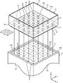
- FIG. 3 is a perspective view of the part of the stage 12 and the material feeder 14 at the feed position P 1 .
- FIG. 3 illustrates the material feeder 14 away from the stage 12 for the purpose of the description.
- the material feeder 14 includes a tank 31 , a shutter 32 , and a vibrator 33 .
- the shutter 32 is an example of an opening-closing part and may be also referred to as a wall part, an obstructing part, a blocking part, a regulating part, or an adjusting pact, for example.
- the tank 31 is formed into a substantially quadrangular box type.
- the tank 31 has an upper face 31 a and a lower face 31 b .
- the upper face 31 a faces upward and is formed flat.
- the lower face 31 b which is located on the opposite side of the upper face 31 a , faces downward and is formed flat.
- the lower face 31 b faces the upper face 25 a of the platform 25 .
- the tank 31 is provided with a container 35 , a bottom wall 36 , and a plurality of feed ports 37 .
- the bottom wall 36 is an example of a first wall and may be also referred to as a lower part or a bottom part, for example.
- the feed ports 37 are an example of first openings, and may be also referred to as ejection ports, holes, or dropping parts, for example.
- the container 35 forms cuboid-shaped recessed part that is formed into a quadrangle-shaped in a plan view and that communicates with the upper face 31 a of the tank 31 .
- the container 35 has a flat bottom face 35 a .
- the bottom face 35 a is a quadrangular flat face of 250 mm ⁇ 250 mm. That is to say, the area of the bottom face 35 a of the container 35 is substantially equal to the area of the upper face 25 a of the platform 25 .
- the shape of the container 35 is not limited to this example.
- the container 35 contains a powdery material 2 .
- the opening part of the container 35 in the upper face 31 a of the tank 31 (the upper end of the container 35 ) is opened, but may be blocked with an openable and closable cover, for example.
- the bottom wall 36 is a quadrangular plate-shaped part that forms the lower face 31 b of the tank 31 and the bottom face 35 a of the container 35 .
- the bottom wall 36 is a part of the tank 31 that exists between the lower face 31 b of tank 31 and the bottom face 35 a of the container 35 , and is located under the container 35 .
- the material 2 contained in the container 35 is supported by the bottom wall 36 .
- the feed ports 37 are each provided in the bottom wall 36 .
- the feed ports 37 have the substantially same shape each other.
- the feed ports 37 extend in the direction along the Z-axis and are each communicated with the container 35 .
- the feed ports 37 each have a feed hole 41 and an introducing part 42 .
- the introducing part 42 may be also referred to as a hopper, a funnel part, or a conical part, for example.
- Each feed hole 41 is a circular hole that communicates with the lower face 31 b of the tank 31 .
- the feed hole 41 is provided from the lower face 31 b of tank 31 to a central part in a thickness direction of the bottom wall 36 .
- the diameter of the feed hole 41 is 6 times or more of the particle size of the material 2 and, for example, is 0.24 mm.
- the shape and diameter of the feed hole 41 are not limited to these examples.
- Each introducing part 42 forms a conical recessed part that communicates with the bottom face 35 a of the container 35 .
- the introducing part. 42 is communicated with the feed hole 41 .
- the inner circumferential face of the introducing part 42 gradually narrows from the opening part in the bottom face 35 a toward the downward feed hole 41 .
- the feed ports 37 are arranged at a substantially uniform Interval in the direction along the X-axis and the direction along the Y-axis. In other words, the feed ports 37 are arranged in the form of grid points.
- the feed ports 37 are arranged in a square-lattice shape, but may be arranged in other arrangements, such as a rhombic-lattice shape and a regular-triangle-lattice shape.
- the feed ports 37 are not limited to the form of grid points and may be arranged in other arrangements.
- the distance (pitch) between one feed port 37 and another one next, to the feed port 37 is, for example, 1 mm.
- the pitch between the feed ports 37 is not limited to this example.
- the opening part of one introducing part. 42 in the bottom, face 35 a of the container 35 may be in contact with or spaced from the opening part of another introducing part 42 next to the introducing part 42 .
- the shutter 32 has a closure wall 45 and a plurality of communicating holes 46 .
- the closure wall 45 is an example of a movable part and a second wall, and may be also referred to as a closing part or a sliding part, for example.
- Each communicating hole 46 is an example of a second opening and may be also referred to as a communicating part, an opening part, or a hole, for example.
- the closure wall 45 is a substantially Quadrangular plate-like shaped, member that covers the lower face 31 b of the tank 31 .
- the shape of the closure wall 45 is not limited to this example.
- the closure wall 45 has an upper face 45 a and a lower face 45 b .
- the upper face 45 a is in contact with the lower face 31 b of the tank 31 .
- the lower face 45 b which is located on the opposite side of the upper face 45 a , faces downward and is formed flat.
- the lower face 45 b of the closure wall 45 faces the upper face 25 a of the platform 25 .
- the height (a position in the direction along the Z-axis) of the lower face 45 b of the closure wall 45 is substantially equal to the height of the upper end 26 a of the circumferential wall 26 .
- the closure wall 45 blocks the opened upper end 26 a of the circumferential wall 26 .
- the communicating holes 46 are each provided in the closure wall 45 .
- Each communicating hole 46 is a circular hole provided from the upper face 45 a of the closure wall 45 to the lower face 45 b thereof.
- the diameter of the communicating hole 46 is 0.24 mm, for example, similarly to the diameter of the feed hole 41 .
- the communicating holes 46 are arranged at a substantially uniform interval in the direction along the X-axis and the direction along the Y-axis, similarly to the feed ports 37 .
- the distance (pitch) between one communicating hole 46 and another one next to the communicating hole 46 is 1 mm, for example, similarly to the interval of the feed ports 37 . That is to say, the communicating holes 46 are arranged in the same direction as the feed ports 37 and at the same interval, as the feed ports 37 .
- the closure wall 45 can move, for example, in the direction along the X-axis, with various devices including an actuator.
- the movement direction of the closure wall 45 is not limited to this example.
- the closure wall 45 moves between an opening position P 3 and a closing position P 1 , for example.
- the opening position P 3 is an example of a second position.
- the closing position P 4 is an example of a first position.
- FIGS. 2 and 3 illustrate the closure wall 45 at the opening position P 3 .
- each feed hole 41 is opened by the corresponding communicating hole 46 .
- FIG. 4 is a sectional view of the part of the stage 12 and the material feeder 14 with the closure wall 45 being at the closing position P 4 .
- the closure wall 45 is moved to the closing position P 4 , the positions of the communicating holes 46 are shifted from the corresponding feed holes 41 of the feed ports 37 .
- the closure wall 45 at the closing position P 4 closes the feed holes 41 of the feed ports 37 .
- the material feeder 14 is moved by the moving device 13 to the feed position P 1 .
- the closure wall 45 is moved to the opening position P 3 .
- the feed holes 41 of the feed ports 37 are opened by the corresponding communicating holes 46 .
- the powdery material 2 contained in the container 35 falls by gravity from the feed ports 37 and communicating holes 46 .
- the material 2 in the container 35 is led to the feed hole 41 via the sloped inner circumferential face of each, introducing part 42 .
- the fall amount of powders per unit time is substantially constant regardless of the height of the material 2 contained in the container 35 , similarly to hourglasses.
- the container 35 may be provided with a partitioning plate corresponding to each feed port 37 .
- the partitioning plate partitions the material 2 contained in the container 35 , and causes the material 2 to be uniformly led to the corresponding introducing part 42 of the feed port 37 .
- the vibrator 33 is, for example, a motor that turns an eccentric weight.
- the vibrator 33 vibrates the material feeder 14 .
- the vibration of the material feeder 14 facilitates the material 2 in the container 35 falling from the feed ports 37 and communicating holes 46 .
- the optical device 15 illustrated in FIG. 1 includes various parts, such as a light source that, has an oscillation element and emits a laser beam L, at conversion lens that converts the laser beam L into a parallel beam, a converging lens that causes the laser beam to converge, and a galvano mirror that moves an irradiated position of the laser beam L.
- the optical device 15 can change the power density of the laser beam L.
- the optical device 15 is located above the stage 12 .
- the optical device 15 may be placed at another place.
- the optical device 15 converts the laser beam L that the light source emits into a parallel beam with the conversion lens.
- the optical device 15 causes the laser beam L to reflect on the galvano mirror, which can change its tilt angle, and causes the laser beam L to converge with the converging lens, to irradiate the desired position with the laser beam L.
- the material replenishing device 16 can contain more material 2 than the container 35 .
- the material replenishing device 16 is placed above the standby position P 2 and has an openable and closable door. When the material feeder 14 is at the standby position P 2 , the door faces the container 35 , which communicates with the upper face 31 a of the tank 31 .
- the material replenishing device 16 opens the door and feeds the material 2 to the container 35 .
- the material replenishing device 16 closes the door to prevent the material 2 from falling.
- the controller 17 is electrically connected to the stage 12 , the moving device 13 , the material feeder 14 , the optical device 15 , and the material replenishing device 16 .
- the controller 17 has various electronic components, such as a CPU, a ROM, and a RAM.
- the controller 17 reads and executes a program stored in the ROM or other storage devices to control the stage 12 , the moving device 13 , the material feeder 14 , the optical device 15 , and the material replenishing device 16 .
- the three-dimensional printer forms the manufactured object 3 based on the control (program) of the controller 17 .
- three-dimensional shape data of the manufactured object 3 is input to the controller 17 of the three-dimensional printer 1 , for example, from an external personal computer.
- the three-dimensional shape data is data for CAD, for example, but is not limited to this example.
- the material replenishing device 16 feeds the material 2 to the container 35 of the material feeder 14 at the standby position P 2 .
- the controller 17 weighs the material 2 contained in the container 35 with a sensor, for example, and forces the material replenishing device 16 to feed the material 2 to the container 35 until the weight reaches a certain value. As a result, the container 35 contains a certain amount of the material 2 . When the container 35 has already contained a certain amount of the material 2 , feeding the material 2 from the material replenishing device 16 may be omitted.
- the closure wall 45 of the material feeder 14 is usually located at the closing position P 4 .
- the feed port 37 is closed by the closure wall 45 , and it is prevented that the material 2 contained in the container 35 falls from the feed ports 37 .
- the moving device 13 moves the material feeder 14 from the standby position P 2 to the feed position P 1 .
- the material feeder 14 feeds the material 2 onto the stage 12 as follows.
- a base 51 is mounted and fixed on the upper face 25 a of the platform 25 of the stage 12 .
- the base 51 is provided to form the manufactured object 3 thereon.
- the manufactured object 3 may be directly formed on the upper face 25 a of the platform 25 , without the base 51 being placed on the upper face 25 a of the platform 25 .
- the base 51 is a quadrangular plate-like shaped member, for example.
- the shape of the base 51 is not limited to this example, and is determined depending on the shape of the manufactured object 3 .
- the base 51 has a flat upper face 51 a .
- the upper face 51 a of the base 51 is parallel to the upper face 25 a of the platform 25 .
- the platform 25 of the stage 12 is placed so that the distance between the upper face 51 a of the base 51 and the upper end 26 a of the circumferential wall 6 in the direction along the Z-axis is 50 ⁇ m.
- the distance between the upper face 51 a of the base 51 and the lower face 45 b of the closure wall 45 of the material feeder 14 at the feed position P 1 is 50 ⁇ m.
- the material 2 is spread all over around the base 51 in advance.
- a surface 2 a of the material 2 spread all over forms the substantially same plane as the upper face 51 a of the base 51 .
- the material 2 and the base 51 form a single layer ML 1 on the upper face 25 a of the platform 25 .
- the surface 2 a of the material 2 and the upper face 51 a of the base 51 that forms the layer ML 1 form a feed region R.
- the feed region R is an example of a region to which material is fed.
- the feed region R is also formed by a plurality of layers ML 2 , ML 3 , ML 4 , . . . of the material 2 , which are piled on the layer ML 1 , as described below.
- the feed region R is a substantially flat, quadrangular face of 250 mm ⁇ 250 mm, similarly to the upper face 25 a of the platform 25 .
- the shape of the feed region R may be different from the shape of the upper face 25 a of the platform 25 .
- the distance between the feed region R and the lower face 45 b of the closure wall 45 of the material feeder 14 at the feed position P 1 is 50 ⁇ m.
- the distance between the feed region R and the lower face 45 b of the closure wall 45 may be changed to, for example, 30 ⁇ m and 100 ⁇ m, by the control of the platform 25 caused by the controller 17 .
- the feed region R is surrounded by the circumferential wall 26 .
- the bottom wall 36 of the material feeder 14 at the feed position P 1 is located above the feed region R.
- the bottom wall 36 covers the entirety of the feed region R.
- the bottom wall 36 may partially cover the feed region. R.
- the lower face 31 b of the tank 31 and the lower face 45 b of the closure wall 45 face the feed region R.
- the controller 17 causes the closure wall 45 to move to the opening position P 3 . This causes the communicating holes 46 of the shutter 32 to be communicated with the corresponding feed holes 41 of the feed, ports 37 , and causes the feed ports 37 to be opened.
- the material feeder 14 is vibrated by the vibrator 33 . As a result, through the feed ports 37 and the communicating holes 46 , the material 2 in the container 35 falls onto the feed region R. The material feeder 14 feeds the material 2 to the feed region R from the feed ports 37 in parallel. The first material feeder 14 may not have the vibrator 33 . If there were no vibration caused by the vibrator 33 , the material 2 falls by gravity from the feed ports 37 and communicating holes 46 .
- the feed region R is defined as it having a plurality of divided sections RD, in the present specification.
- the divided sections RD are an example of a plurality of sections.
- the divided sections RD are quadrangular sections, for example.
- Each divided section RD is not limited to this example and may be other shapes.
- Each of the divided sections RD has a substantially same shape each other.
- the areas of the divided sections RD are equal to each other.
- the divided sections RD are each arranged in the direction along the X-axis and the direction along the Y-axis.
- the feed ports 37 and communicating holes 46 face the corresponding divided sections RD. That is to say, each feed port 37 and communicating hole 46 is located above the corresponding divided section RD, and oppose (face) the divided section RD.
- FIG. 3 illustrates respective fall spots S of the material 2 that has fallen from each feed port 37 and communicating hole 46 .
- Each fall spot S is an example of a position to which the material is fed.
- the fall spot 8 is located in the divided section RD corresponding to each feed port 37 and communicating hole 46 .
- each fall spot S to which the material 2 falls from corresponding feed port 37 and communicating hole 46 moves within the corresponding divided section RD, as indicated by the arrow in FIG. 3 .
- the fall spot S moves within the divided section RD so as to trace with a single stroke.
- the material 2 is substantially evenly fed to each divided section RD.
- the material 2 is fed to each divided section RD, so that the feed region R is filled with a layer of the material fed to the divided section RD and a continuous layers ML 2 of the material 2 is formed, throughout the entirety of the feed, region R.
- the layer ML 2 of the material 2 is placed on the layer ML 1 .
- the amount of the material 2 fed to each divided section RD is substantially equal.
- the thickness of the layer ML 2 formed in the feed region R is substantially equal regardless of its position.
- each communicating hole 46 is closed by the material 2 .
- the controller 17 counts, for example, with a timer, an elapsed time after the closure wall 45 moves to the opening position P 3 and the feed ports 37 are opened.
- the controller 17 causes the closure wall 45 to move from the opening position P 3 to the closing position P 4 and causes the closure wall 45 to close the feed ports 37 .
- the fall speed of powders that, pass each feed port 37 is substantially constant, and thus the fall amount thereof can be controlled with times for which the feed ports 37 are opened.
- the lower face 45 b of the closure wall 45 which moves from the opening position P 3 to the closing position P 4 , slides on the surface 2 a of the material. 2 in contact with the lower face 45 b . This causes the surface 2 a of the fed material 2 to be leveled.
- the moving device 13 moves the material feeder 14 from the feed position P 1 to the standby position P 2 .
- the lower face 45 b of the closure wall 45 slides on the surface 2 a of the material 2 in contact with, the lower face 45 b . This causes the surface 2 a of the fed material 2 to be further flattened.
- the controller 17 controls the optical device 15 to cause if to irradiate the material 2 that forms the layer ML 2 with the laser beam L from the optical device 15 .
- the controller 17 determines an irradiated position of the laser beam L, based on the input three-dimensional shape data of the manufactured object 3 .
- the part irradiated with the laser beam L melts.
- the material 2 is irradiated with the laser beam L to be solidified after being partially melted.
- a part (one layer) of the manufactured object 3 is formed in the layer ML 2 of the material 2 .
- the material 2 may be sintered.
- the material replenishing device 16 feeds the material 2 to the container 35 of the material feeder 14 .
- the volume of the material 2 contained in the container 35 is larger than the volume of the layer ML 2 of the material 2 formed in the feed region R.
- the platform 25 moves downward, for example, by 50 ⁇ m.
- the distance by which the platform 25 moves is equal to the thickness of the layer ML 2 .
- the distance between the surface 2 a of the material 2 that forms the layer ML 2 and the upper end 26 a of the circumferential wall 26 is 50 ⁇ m.
- the surface 2 a of the material 2 that forms the layer ML 2 and the surface of the part, of the manufactured object 3 formed in the layer ML 2 form the feed region R in the layer ML 2 .
- the moving device 13 moves the material feeder 14 to the feed position P 1 again.
- the material feeder 14 feeds the material 2 to the feed region R that the layer ML 2 forms, at the feed position P 1 .
- FIG. 5 is a sectional view of the stage 12 with the manufactured object 3 being formed.
- the material feeder 14 stacks the material 2 similarly to the above description, and sequentially forms a plurality of layers ML 2 , ML 3 , ML 4 , . . . of the material 2 .
- the layers ML 2 , ML 3 , ML 4 , . . . are divided by a two-dot chain line.
- the optical device 15 partially melts the material 2 of the layers ML 2 , ML 3 , ML 4 , . . . , and forms a part of the manufactured object 3 , each time the layers ML 2 , ML 3 , ML 4 , . . . are formed.
- the three-dimensional printer 1 repeats the formation of the layers ML 2 , ML 3 , ML 4 , . . . of the material 2 caused by the material feeder 14 and the fusion of the material 2 caused by the optical device 15 to form the three-dimensionally shaped manufactured object 3 .
- the manufactured object 3 which is formed within the treatment tank 11 , is taken out of the treatment chamber 11 a by the opening of a cover of the treatment tank 11 , for example.
- the manufactured object 3 may be conveyed outside the treatment chamber 11 a by a conveying device having a conveyance arm and other components, for example.
- the manufactured object 3 is conveyed to a room (an antechamber) that is isolated from the treatment chamber 11 a by an openable and closable door, for example.
- the material feeder 14 feeds the material 2 from the feed ports 37 provided in the bottom wall 36 to the feed region R in parallel to form the layer ML 2 , ML 3 , ML 4 , . . . of the material 2 in (to place the material 2 on) the feed region R.
- region R causes the forming time of the layers ML 2 , ML 3 , ML 4 , . . . of the material 2 in the feed region R to be constant regardless of the size of the feed region R.
- the forming time of the layers ML 2 , ML 3 , ML 4 , . . . of the material 2 is the same as the present, embodiment.
- the material 2 falls by gravity from the feed ports 37 , so that the material 2 is fed to the feed region R.
- their fall speed is substantially constant regardless of the height of the material 2 in the container 35 , similarly to hourglasses.
- the feed amount is relatively easily controlled using the opening time of the feed ports 37 .
- the feed ports 37 are placed in the bottom wall 36 in the form of grid point. This equalizes the distance between the positions (the fall spots S) to which the material 2 is fed and reduces the variation of the amount of the material 2 in the feed region R.
- the shutter 32 opens and closes the feed ports 37 .
- the material feeder 14 is at a position off from the feed region R, such as the standby position P 2 , the exit of the material 2 from the feed ports 37 is suppressed.
- the configuration that suppresses the material from leaking is implemented in a relatively simple configuration.
- the closure wall 45 closes the feed ports 37 .
- the communicating holes 46 each communicate with the feed ports 37 , and the feed ports 37 are opened. This causes the feed port 37 to be opened and closed easily.
- the vibrator 33 vibrates the material feeder 14 to facilitate the material 2 falling from the feed ports 37 to the feed region R. As a result, the material is evenly fed from the feed ports 37 .
- the material feeder 14 in which the feed ports 37 each feed the material 2 to the corresponding divided sections RD, forms the continuous layers ML 2 , ML 3 , ML 4 , . . . of the material 2 in the feed region R. This shortens the distance by which the material feeder 14 moves above the feed region R to within the extent of the divided section RD, and reduces the forming time of the layers ML 2 , ML 3 , ML 4 , . . . of the material 2 in the feed region R. In other words, the layers ML 2 , ML 3 , ML 4 , . . . are formed by feeding the material to each divided section RD in parallel.
- each feed port 37 feeds the material 2 to the corresponding divided section RD, to form the layers ML 2 , ML 3 , ML 4 , . . . of the material 2 in the feed region R.
- the material feeder 14 moves sac that the fall spots S of the material 2 move within the divided sections RD. As a result, the material 2 is fed to each of the divided sections RD thoroughly, and the material 2 is evenly fed to the feed region R.
- the controller 17 controls the opening time of the feed ports 37 with the shutter 32 , and closes the feed ports 37 when a certain time has elapsed after the feed ports 37 being opened. This causes the amount of the material 2 fed to the feed region R to be constant.
- the closure wall 45 moves from the opening position P 3 to the closing position P 4 to level the layers ML 2 , ML 3 , ML 4 , . . . of the material 2 formed in the feed region R.
- the surface 2 a of the material 2 fed to the feed region R is easily flattened and the material 2 is evenly melted by the laser beam L.
- the material replenishing device 16 feeds the material 2 to the container 35 of the material feeder 14 at the standby position P 2 .
- the material 2 is fed to the container 35 while the layers ML 2 , ML 3 , ML 4 , . . . of the material 2 is melted by the optical device 15 , and the manufactured object 3 is effectively formed.
- a component having the same function as an aforementioned component has the same reference sign as the aforementioned component, and the description thereof may be omitted.
- the components with the same reference sign are not limited to have all functions and properties in common, but may have different functions and properties according to each embodiment.
- FIG. 6 is a partially perspective view of the stage 12 and the material feeder 14 at the feed position P 1 according to the second embodiment.
- FIG. 6 illustrates the material 2 contained in the container 35 in a two-dot chain line.
- the tank 31 of the second embodiment is provided with a plurality of first slits 61 instead of the feed ports 37 .
- Each first slit 61 is an example of the first opening.
- the first slits 61 are each provided in the bottom wall 36 .
- the first slits 61 are provided from the lower face alb of the tank 31 to the bottom face 35 a of the container 35 and extend, for example, in the direction along the Y-axis.
- the direction along the Y-axis is an example of a first direction.
- the first slits 61 are arranged at a substantially uniform interval in the direction along the X-axis.
- the direction along the X-axis is an example of a second direction.
- the width (the dimension in the direction along the X-axis) of each first slit 61 is 6 times or more of the particle size of the material 2 and, for example, is 0.24 mm.
- the shape and width of each first slit 61 are not limited to these examples.
- the shutter 32 of the second embodiment has a plurality of closure plates 64 instead of the closure wall 45 .
- Each closure plate 64 is an example of a second wall.
- the closure plates 64 extend in the direction along the Y-axis.
- the closure plates 64 are arranged at a substantially uniform interval in the direction along the X-axis.
- the width (the dimension in the direction along the X-axis) of each closure plate 64 is either substantially equal to or larger than the width of the first slit 61 .
- each closure plate 64 One end in the direction along the X-axis of each closure plate 64 is provided with a knife edge 64 a .
- Each knife edge 64 a is a part of the closure plate 64 , which has the bottom face of the closure plate 64 that faces downward and the side face of the closure plate 64 that slants at an acute angle to the bottom face.
- Second slits 65 are each provided between the closure plates 64 .
- the second slits 65 extend in the direction along the Y-axis.
- the second slits 65 are arranged at a substantially uniform interval in the direction along the X-axis.
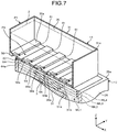
- FIG. 7 is a partially perspective view of the stage 12 and the material feeder 14 with the closure plates 64 being at the closing position P 4 .
- the closure plates 64 are integrally movable in the direction along the X-axis.
- the closure plates 64 may be individually movable.
- the closure plates 64 move between the opening position P 3 illustrated in FIG. 6 and the closing position P 4 illustrated in FIG. 7 .
- the closure plates 64 at the opening position P 3 overlap the bottom wall 36 , which is provided with the first slits 61 .
- the second slits 65 of the shutter 32 communicate with the corresponding first slits 61 of the tank 31 . This causes the first slits 61 to be opened.
- the closure plates 64 at the closing position P 4 close the first slits 61 .
- the knife edges 64 a of the closure plates 64 each contacts a plurality of receiving parts 36 a provided in the bottom wall 36 .
- Each receiving part 36 a projects from the lower face 31 b of the tank 31 and is a convex part that extends in the direction along the Y-axis.
- the material feeder 14 of the second embodiment described above moves the closure plates 64 to the opening position P 3 , at the feed position P 1 . This causes the first slits 61 to be opened. The material 2 contained in the container 35 falls from the first slits 61 to the feed region R in parallel.
- the material feeder 14 moves in the direction along the X-axis. In other words, the material feeder 14 moves in a direction intersecting the direction to which the first slits 61 extend. As a result, the material 2 is fed to the feed region R thoroughly.
- the receiving parts 36 a and the closure plates 64 slide on the surface of the fed material 2 and level the surface of the material 2 .
- the material feeder 14 moves the closure plates 64 to the closing position P 4 .
- the closure plates 64 is provided with the knife edges 64 a , so that the closure plates 64 easily moves from the opening position P 3 to the closing position P 4 .
- the closure plates 64 move from the opening position P 3 to the closing position P 4 to close the first slits 61 and to slide on the surface 2 a of the fed material 2 .
- the closure plates 64 level any unevenness formed in the surface 2 a of the material 2 and flatten the surface 2 a of the material 2 .
- the material feeder 14 feeds the material 2 to the feed region R from the first slits 61 in parallel.
- the first opening is not limited the feed port 37 of the first embodiment and the first slit 61 of the second embodiment, and is formed into various shapes.
- FIG. 6 is a sectional view of a part of the stage 12 and the material feeder 14 according to the third embodiment.
- the material feeder 14 of the third embodiment further has an obstructing part 71 .
- the obstructing part is an example of an opening-closing part.
- the obstructing part 71 has a plurality of pistons 72 and a supporting member 73 .
- Each piston 72 is an example of a valve member and may be also referred to as a structure, an extrusion part, a pressurization part, an insertion part, or a plug, for example.
- the supporting member 73 may be also referred to as a coupling unit or a moving unit.
- Each piston 72 is formed into a rod shape that extends in the direction along the Z-axis.
- One end of the piston 72 is provided with a valve part 72 a .
- Each valve part 72 a has a shape corresponding to the feed port 37 . That is to say, the valve part 72 a has a rod-shaped part that can fit into the feed hole 41 and a conical part that can fit into the introducing part 42 .
- the pistons 72 are placed in the container 35 so that the valve parts 72 a face the corresponding feed ports 37 .
- the valve parts 72 a of the pistons 72 are buried in the material 2 contained in the container 35 .
- the valve parts 72 a may be located outside the container 35 .
- the supporting member 73 supports the pistons 72 .
- the pistons 72 which are supported by the supporting member 73 , are arranged at a substantially uniform interval in the direction along the X-axis and the direction along the Y-axis. That is to say, the pistons 72 are arranged in the same manner as the feed ports 37 and at the same interval as the feed ports 37 .
- the supporting member 73 can move the pistons 72 in the direction along the Z-axis, with various devices including an actuator. In other words, the supporting member 73 moves the pistons 72 , which is provided with the valve parts 72 a , in a direction intersecting the bottom wall 36 .
- the pistons 72 may be individually movable.
- FIG. 9 is a sectional view of the part of the stage 12 and the material feeder 14 with the pistons 72 being at a closing position P 6 .
- the pistons 72 move between an opening position P 5 illustrated in FIG. 8 and the closing position P 6 illustrated in FIG. 9 , for example.
- the pistons 72 at the opening position P 5 are spaced from the feed port 37 .
- the valve parts 72 a of the pistons 72 at the opening position P 5 are spaced from the corresponding feed ports 37 to open the feed ports 37 .
- valve parts 72 a of the pistons 72 at the closing position P 6 fit into the corresponding feed ports 37 .
- the conical part of each valve part 72 a is very close to the introducing part 42 . In this manner, the valve parts 72 a moved to the closing position P 6 close the feed ports 37 .
- the material feeder 14 of the third embodiment described above moves the pistons 72 to the opening position P 5 , at the feed position P 1 . This causes the feed port 37 to be opened. The material 2 contained in the container 35 falls from the feed ports 37 to the feed region R in parallel.
- the pistons 72 moved to the opening position P 5 gradually moves towards the closing position P 6 .
- the valve part 72 a of each piston 72 which moves from the opening position P 5 to the closing position P 6 , pushes the material 2 located between the valve part 72 a and the feed port 37 towards the feed port 37 .
- the material 2 is extruded from the feed ports 37 by the pistons 72 and is fed to the feed region R.
- valve parts 72 a of the pistons 72 which have arrived at the closing position P 6 , fit into the feed ports 37 to close the feed ports 37 . That is to say, when a certain time has elapsed after the pistons 72 opening the feed ports 37 , the valve parts 72 a of the pistons 72 close the feed ports 37 . As a result, the material 2 is fed to the feed region R.
- the pistons 72 at the closing position P 6 fit into the feed ports 37 to close the feed ports 37 . This causes the feed ports 37 to be opened and closed easily.
- the pistons 72 move from the opening position P 5 to the closing position P 6 , to each extrude the material 2 in the container 35 into the feed ports 37 and fit into the feed ports 37 to close the feed ports 37 . This further reduces the feeding time of the material 2 to the feed region R, and causes the amount of the material 2 to be constant more easily.
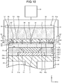
- FIG. 10 is a sectional view of a part of the stage 12 and the material feeder 14 according to the fourth embodiment.
- the three-dimensional printer 1 of the fourth embodiment further has an air supplying device 81 .
- the air supplying device 81 is an example of a blowing part.
- the air supplying device 81 is an air compressor, for example.
- the air supplying device 81 is communicated with the material feeder 14 through a plurality of tubes 82 .
- Each tube 82 is formed of a flexible synthetic resin, for example.
- the tank 31 of the material feeder 14 is provided with a plurality of air supply paths 84 .
- One end of each air supply path 84 is communicated with the tube 82 .
- the other end of the air supply path 84 communicates with the lower face 31 b of the tank 31 .
- the closure wall 45 at the opening position P 3 closes the opening parts of the air supply paths 84 in the lower face 31 b of the tank 31 .
- the closure wall 45 of the shutter 32 is provided with a plurality of blow ports 86 .
- Each blow port 86 is a hole provided from the upper face 45 a of the closure wall 45 to the lower face 45 b thereof.
- the blow ports 86 communicate with the corresponding air supply paths 84 . In other words, the blow ports 86 open the air supply paths 94 .
- the platform 25 is lowered so that the distance between the feed region R and the lower face 45 b of the closure wall 45 is 100 ⁇ m. That is to say, the distance between the feed region R and the lower face 45 b of the closure wall 45 is larger than the thickness of the layer of the material 2 that the material feeder 14 forms.
- the material feeder 14 at the feed position P 1 moves the closure wall 45 to the opening position P 3 to open the feed ports 37 .
- the material feeder 14 feeds the material 2 to the feed region R from the feed ports 37 in parallel.
- the controller 17 moves the closure wall 45 to the closing position P 4 .
- This causes the feed ports 37 to be closed by the closure wall 45 .
- the distance between the surface 2 a of the material 2 fed to the feed region R in this way and the lower face 45 b of the closure wall 45 is 50 ⁇ m. That is to say, the lower face 45 b of the closure wall 45 is spaced from the material 2 fed to the feed region R.
- the closure wall 45 moves to the closing position P 4 , so that the air supply paths 84 are opened by the blow ports 86 .
- the air supplying device 81 sends air (blows air) into a space surround by the circumferential wall 26 and the closure wall 45 through the tubes 82 , the air supply paths 84 , and the blow ports 86 .
- FIG. 11 is a sectional view of the part of the stage 12 with the material 2 being raised and the material feeder 14 .
- the air supplying device 81 sends air into the space surrounded by the circumferential wall 26 and the closure wall 45 , to raise the material 2 fed to the feed region R.
- the material 2 flies in the air in the space surrounded by the circumferential wall 26 and the closure wall 45 .
- the air sent into the space surrounded by the circumferential wall 26 and the closure wall 45 comes out of a vent (ventilation hole) provided in the material feeder 14 , for example.
- the air supplying device 81 stops the blow. As a result, the material 2 that flies in the air falls to the feed region R.
- the fallen material 2 forms the substantially uniform layers ML 2 , ML 3 , ML 4 , . . . in the feed region R.
- the material 2 is stirred by the air supplying device 81 , but the material 2 may be stirred by other means, such as brushes.
- FIG. 12 is a sectional view of the part of the stage 12 with the material 2 being pressed and the material feeder 14 .
- the material feeder 14 moves towards the feed region R.
- the closure wall 45 enters into the circumferential wall 26 and pushes the material 2 stacked on the feed region R. This improves the density (the filling rate) of the layers ML 2 , ML 3 , ML 4 , . . . of the material 2 .
- the air supplying device 81 sends air to the space surrounded by the closure wall 45 and the circumferential wall 26 to raise the material 2 fed to the feed region R.
- the raised material 2 falls to the feed region R to form the layers ML 2 , ML 3 , ML 4 , . . . , which have a substantially uniform thickness.
- the surface 2 a of the material 2 fed to the feed region R is easily flattened.
- FIG. 13 is a partially sectional view of the stage 12 and the material feeder 14 according to the fifth embodiment.
- the material feeder 14 of the fifth embodiment further has an internal shutter 91 .
- the internal shutter 91 is an example of the opening-closing part.
- the internal shutter 91 is placed on the bottom face 35 a of the container 35 .
- the internal shutter 91 is not limited to this example, and may be provided within the bottom wall 36 , for example.
- the internal shutter 91 is provided with an upper closure wall 92 and a plurality of upper communicating holes 93 .
- the upper closure wall 92 is a substantially quadrangular plate-like member that covers the bottom face 35 a of the container 35 .
- the shape of the upper closure wall 92 is not limited to this example.
- the upper closure wall 92 has an upper face 92 a and a lower face 92 b .
- the upper face 92 a supports the material 2 contained in the container 35 .
- the lower face 92 b is located on the opposite side of the upper face 92 a and is in contact with the bottom face 35 a of the container 35 .
- the upper communicating holes 93 are each provided in the upper closure wall 92 .
- Each upper communicating hole 93 is a circular hole provided from the upper face 92 a of the upper closure wall 92 to the lower face 92 b thereof.
- the diameter of the upper communicating hole 93 is substantially equal to the diameter of the opening part (the upper end of the introducing part 42 ) of the introducing part 42 , the opening part provided in the bottom face 35 a of the container 35 .
- the shape and diameter of the upper communicating hole 93 are not limited to these examples.
- the upper communicating holes 93 are arranged at a substantially uniform interval in the direction along the X-axis and the direction along the Y-axis, similarly to the feed ports 37 .
- the distance (pitch) between one upper communicating hole 93 and another one next to the upper communicating hole 93 is 1 mm, for example, similarly to the interval of the feed ports 37 . That is to say, the upper communicating holes 93 are arranged in the same manner as the feed ports 37 and at the same interval as the feed ports 37 .
- the upper closure wall 92 can move, for example, in the direction along the X-axis, with various devices including an actuator.
- the movement direction of the upper closure wall 92 is not limited to this example.
- the upper closure wall 92 moves between an opening position P 7 and a closing position P 8 , for example.
- FIG. 13 illustrates the upper closure wall 92 at the closing position P 8 .
- FIG. 13 illustrates the upper closure holes 93 with the upper closure wall 92 being at the closing position P 7 , in a two-dot chain line.
- the upper communicating holes 93 each communicate with the introducing parts 42 of the feed ports 37 . That is to say, the introducing parts 42 are each opened by the corresponding upper communicating holes 93 .
- the material feeder 14 of the fifth embodiment described above moves the upper closure wall 92 to the opening position P 7 when the closure wall 45 is at the closing position P 4 .
- the feed ports 37 are each filled with the material 2 in the container 35 .
- the material 2 with which the feed ports 37 are filled is supported by the closure wall 45 at the closing position P 4 .
- the volume of each feed port 37 is equal to the volume of the corresponding divided section RD to which the feed port 37 supplies the material 2 .
- the material feeder 14 at the feed position P 1 moves the closure wall 45 to the opening position P 3 .
- the feed ports 37 are opened and the material 2 held in each feed port 37 is fed from each feed port 37 to the feed region R.
- the upper closure wall 92 prevents the material 2 contained in the container 35 from flowing into the feed ports 37 .
- Each feed port 37 feeds the holding material 2 to the corresponding divided section RD, so that the layers ML 2 , ML 3 , ML 4 , . . . of the material 2 is formed in the feed region R and each feed port 37 empties.
- each feed port 37 holds a certain amount of the material 2 . This causes the amount of the material 2 fed to the feed region R to be constant.
- a feeding unit feeds a material from a plurality of first openings provided in a first wall to a region in parallel to form a layer of the material in the region. This shortens the distance by which the feeding unit moves above the region, and reduces feeding time of the powdery material.
- the three-dimensional printer 1 melts the material 2 with the laser beam L to form the manufactured object 3 .
- the three-dimensional printer 1 is not limited to this example, and may feed, for example, a bonding agent (a binder) to the material 2 with an ink jet and other devices, to solidify the material 2 partially to form the manufactured object 3 .
- the material 2 is not limited to a metal, and may be other materials, such as a resin.
- the three-dimensional printer 1 uses the laser beam L as an energy ray for melting the material 2 .
- an energy ray may be, as far as melting the material similarly to the laser beam L, for example, an electron beam and an electromagnetic wave from a microwave region to an ultraviolet region.
Landscapes
- Engineering & Computer Science (AREA)
- Chemical & Material Sciences (AREA)
- Manufacturing & Machinery (AREA)
- Materials Engineering (AREA)
- Mechanical Engineering (AREA)
- Physics & Mathematics (AREA)
- Optics & Photonics (AREA)
- Robotics (AREA)
- Composite Materials (AREA)
- Powder Metallurgy (AREA)
Abstract
Description
Claims (7)
Applications Claiming Priority (3)
| Application Number | Priority Date | Filing Date | Title |
|---|---|---|---|
| JP2014060395A JP5917586B2 (en) | 2014-03-24 | 2014-03-24 | Material supply apparatus and additive manufacturing apparatus for additive manufacturing apparatus |
| JP2014-060395 | 2014-03-24 | ||
| PCT/JP2014/073982 WO2015145812A1 (en) | 2014-03-24 | 2014-09-10 | Material supply device for laminate molding device, laminate molding device, and laminate molding method |
Publications (2)
| Publication Number | Publication Date |
|---|---|
| US20170014902A1 US20170014902A1 (en) | 2017-01-19 |
| US10695834B2 true US10695834B2 (en) | 2020-06-30 |
Family
ID=54194390
Family Applications (1)
| Application Number | Title | Priority Date | Filing Date |
|---|---|---|---|
| US15/124,270 Expired - Fee Related US10695834B2 (en) | 2014-03-24 | 2014-09-10 | Material feeder of additive manufacturing apparatus, additive manufacturing apparatus, and additive manufacturing method |
Country Status (4)
| Country | Link |
|---|---|
| US (1) | US10695834B2 (en) |
| JP (1) | JP5917586B2 (en) |
| DE (1) | DE112014006500T5 (en) |
| WO (1) | WO2015145812A1 (en) |
Families Citing this family (21)
| Publication number | Priority date | Publication date | Assignee | Title |
|---|---|---|---|---|
| JP5951668B2 (en) | 2014-03-24 | 2016-07-13 | 株式会社東芝 | Material supply apparatus and additive manufacturing apparatus for additive manufacturing apparatus |
| CN106488819B (en) | 2014-06-20 | 2018-06-22 | 维洛3D公司 | Apparatus, system and method for three-dimensional printing |
| US10328525B2 (en) | 2015-08-25 | 2019-06-25 | General Electric Company | Coater apparatus and method for additive manufacturing |
| US9676145B2 (en) | 2015-11-06 | 2017-06-13 | Velo3D, Inc. | Adept three-dimensional printing |
| US10071422B2 (en) | 2015-12-10 | 2018-09-11 | Velo3D, Inc. | Skillful three-dimensional printing |
| CN108883575A (en) | 2016-02-18 | 2018-11-23 | 维洛3D公司 | Accurate 3 D-printing |
| US11691343B2 (en) | 2016-06-29 | 2023-07-04 | Velo3D, Inc. | Three-dimensional printing and three-dimensional printers |
| US10286452B2 (en) | 2016-06-29 | 2019-05-14 | Velo3D, Inc. | Three-dimensional printing and three-dimensional printers |
| KR101786384B1 (en) | 2016-09-07 | 2017-11-15 | 현대자동차주식회사 | Apparatus and method manufacturing fiber reinforced plastic products |
| WO2018064349A1 (en) | 2016-09-30 | 2018-04-05 | Velo3D, Inc. | Three-dimensional objects and their formation |
| WO2018128695A2 (en) | 2016-11-07 | 2018-07-12 | Velo3D, Inc. | Gas flow in three-dimensional printing |
| US10611092B2 (en) | 2017-01-05 | 2020-04-07 | Velo3D, Inc. | Optics in three-dimensional printing |
| US20180250744A1 (en) | 2017-03-02 | 2018-09-06 | Velo3D, Inc. | Three-dimensional printing of three-dimensional objects |
| US10449696B2 (en) | 2017-03-28 | 2019-10-22 | Velo3D, Inc. | Material manipulation in three-dimensional printing |
| CN110869193A (en) * | 2017-07-28 | 2020-03-06 | 惠普发展公司,有限责任合伙企业 | Three-dimensional printer using pneumatic conveying |
| CN107379546A (en) * | 2017-09-13 | 2017-11-24 | 王保锋 | A kind of 3D printer machine table |
| US10272525B1 (en) | 2017-12-27 | 2019-04-30 | Velo3D, Inc. | Three-dimensional printing systems and methods of their use |
| US10144176B1 (en) * | 2018-01-15 | 2018-12-04 | Velo3D, Inc. | Three-dimensional printing systems and methods of their use |
| KR20230047214A (en) | 2019-07-26 | 2023-04-06 | 벨로3디, 인크. | Quality assurance in formation of three-dimensional objects |
| JP7323426B2 (en) * | 2019-10-29 | 2023-08-08 | 日本電子株式会社 | 3D additive manufacturing equipment |
| JP2022013004A (en) * | 2020-07-02 | 2022-01-18 | 株式会社リコー | Stereo-lithography equipment |
Citations (19)
| Publication number | Priority date | Publication date | Assignee | Title |
|---|---|---|---|---|
| JPH10264134A (en) | 1997-03-27 | 1998-10-06 | Sumitomo Metal Ind Ltd | Powder filling method and powder filling device |
| US5902537A (en) * | 1995-02-01 | 1999-05-11 | 3D Systems, Inc. | Rapid recoating of three-dimensional objects formed on a cross-sectional basis |
| JP2001158520A (en) | 1999-12-01 | 2001-06-12 | Shinko Electric Co Ltd | Powder supply device |
| US20010045678A1 (en) | 2000-05-25 | 2001-11-29 | Minolta Co., Ltd. | Three-dimensional modeling apparatus |
| US20020105114A1 (en) | 2001-02-07 | 2002-08-08 | Minolta Co., Ltd. | Three-dimensional molding apparatus and three-dimensional molding method |
| JP2002307562A (en) | 2001-02-07 | 2002-10-23 | Minolta Co Ltd | Three-dimensional printing apparatus and three-dimensional printing method |
| WO2007013240A1 (en) | 2005-07-27 | 2007-02-01 | Shofu Inc. | Apparatus for forming layered object |
| JP2007216595A (en) | 2006-02-20 | 2007-08-30 | Matsuura Machinery Corp | Manufacturing equipment for three-dimensional product |
| JP4450304B2 (en) | 2003-04-21 | 2010-04-14 | 日立粉末冶金株式会社 | Feeder for powder molding equipment |
| US8226394B2 (en) * | 2008-01-21 | 2012-07-24 | Sony Corporation | Optical molding apparatus and optical molding method |
| US20130337100A1 (en) * | 2011-04-20 | 2013-12-19 | Dws S.R.L. | Stereolithography Machine for Producing a Three-Dimensional Object and Stereolithography Method Applicable to Said Machine |
| US20150183166A1 (en) * | 2012-09-05 | 2015-07-02 | Aprecia Pharmaceuticals Company | Three-dimensional Printing System and Equipment Assembly |
| US20150231831A1 (en) * | 2014-02-20 | 2015-08-20 | Global Filtration Systems, A Dba Of Gulf Filtration Systems Inc. | Apparatus and method for forming three-dimensional objects using a tilting solidification substrate |
| US20150290710A1 (en) * | 2012-11-06 | 2015-10-15 | Ulf Ackelid | Powder pre-processing for additive manufacturing |
| US9943906B2 (en) * | 2015-12-15 | 2018-04-17 | Denso Corporation | Powder supply apparatus |
| US20180369917A1 (en) * | 2015-12-14 | 2018-12-27 | Safran Aircraft Engines | A device and a method for fabricating a three-dimensional part by selectively melting a powder bed |
| US10259072B2 (en) * | 2013-06-10 | 2019-04-16 | Grid Logic Incorporated | System and method for additive manufacturing |
| US10335901B2 (en) * | 2013-06-10 | 2019-07-02 | Renishaw Plc | Selective laser solidification apparatus and method |
| US10399145B2 (en) * | 2013-06-11 | 2019-09-03 | Renishaw Plc | Additive manufacturing apparatus and method |
-
2014
- 2014-03-24 JP JP2014060395A patent/JP5917586B2/en not_active Expired - Fee Related
- 2014-09-10 WO PCT/JP2014/073982 patent/WO2015145812A1/en not_active Ceased
- 2014-09-10 DE DE112014006500.5T patent/DE112014006500T5/en not_active Ceased
- 2014-09-10 US US15/124,270 patent/US10695834B2/en not_active Expired - Fee Related
Patent Citations (21)
| Publication number | Priority date | Publication date | Assignee | Title |
|---|---|---|---|---|
| US5902537A (en) * | 1995-02-01 | 1999-05-11 | 3D Systems, Inc. | Rapid recoating of three-dimensional objects formed on a cross-sectional basis |
| JPH10264134A (en) | 1997-03-27 | 1998-10-06 | Sumitomo Metal Ind Ltd | Powder filling method and powder filling device |
| JP2001158520A (en) | 1999-12-01 | 2001-06-12 | Shinko Electric Co Ltd | Powder supply device |
| US20010045678A1 (en) | 2000-05-25 | 2001-11-29 | Minolta Co., Ltd. | Three-dimensional modeling apparatus |
| JP2001334583A (en) | 2000-05-25 | 2001-12-04 | Minolta Co Ltd | 3D modeling equipment |
| US20020105114A1 (en) | 2001-02-07 | 2002-08-08 | Minolta Co., Ltd. | Three-dimensional molding apparatus and three-dimensional molding method |
| JP2002307562A (en) | 2001-02-07 | 2002-10-23 | Minolta Co Ltd | Three-dimensional printing apparatus and three-dimensional printing method |
| JP4450304B2 (en) | 2003-04-21 | 2010-04-14 | 日立粉末冶金株式会社 | Feeder for powder molding equipment |
| US20090025638A1 (en) | 2005-07-27 | 2009-01-29 | Shofu Inc | Apparatus for Forming Layered Object |
| WO2007013240A1 (en) | 2005-07-27 | 2007-02-01 | Shofu Inc. | Apparatus for forming layered object |
| JP2007216595A (en) | 2006-02-20 | 2007-08-30 | Matsuura Machinery Corp | Manufacturing equipment for three-dimensional product |
| US8226394B2 (en) * | 2008-01-21 | 2012-07-24 | Sony Corporation | Optical molding apparatus and optical molding method |
| US20130337100A1 (en) * | 2011-04-20 | 2013-12-19 | Dws S.R.L. | Stereolithography Machine for Producing a Three-Dimensional Object and Stereolithography Method Applicable to Said Machine |
| US20150183166A1 (en) * | 2012-09-05 | 2015-07-02 | Aprecia Pharmaceuticals Company | Three-dimensional Printing System and Equipment Assembly |
| US20150290710A1 (en) * | 2012-11-06 | 2015-10-15 | Ulf Ackelid | Powder pre-processing for additive manufacturing |
| US10259072B2 (en) * | 2013-06-10 | 2019-04-16 | Grid Logic Incorporated | System and method for additive manufacturing |
| US10335901B2 (en) * | 2013-06-10 | 2019-07-02 | Renishaw Plc | Selective laser solidification apparatus and method |
| US10399145B2 (en) * | 2013-06-11 | 2019-09-03 | Renishaw Plc | Additive manufacturing apparatus and method |
| US20150231831A1 (en) * | 2014-02-20 | 2015-08-20 | Global Filtration Systems, A Dba Of Gulf Filtration Systems Inc. | Apparatus and method for forming three-dimensional objects using a tilting solidification substrate |
| US20180369917A1 (en) * | 2015-12-14 | 2018-12-27 | Safran Aircraft Engines | A device and a method for fabricating a three-dimensional part by selectively melting a powder bed |
| US9943906B2 (en) * | 2015-12-15 | 2018-04-17 | Denso Corporation | Powder supply apparatus |
Non-Patent Citations (2)
| Title |
|---|
| International Search Report dated Nov. 18, 2014, in PCT/JP2014/073982 filed Sep. 10, 2014. |
| Notice of Rejection dated Dec. 8, 2015, in Japan Application No. 2014-060395 filed Mar. 24, 2014. |
Also Published As
| Publication number | Publication date |
|---|---|
| JP2015182295A (en) | 2015-10-22 |
| US20170014902A1 (en) | 2017-01-19 |
| JP5917586B2 (en) | 2016-05-18 |
| WO2015145812A1 (en) | 2015-10-01 |
| DE112014006500T5 (en) | 2017-02-09 |
Similar Documents
| Publication | Publication Date | Title |
|---|---|---|
| US10695834B2 (en) | Material feeder of additive manufacturing apparatus, additive manufacturing apparatus, and additive manufacturing method | |
| US10744596B2 (en) | Material feeder of additive manufacturing apparatus, additive manufacturing apparatus, and additive manufacturing method | |
| EP3412382B1 (en) | Apparatus with a module for the layered manufacture of a product | |
| JP6811283B2 (en) | Powder recoater for 3D printers | |
| JP6356741B2 (en) | Powder recirculation type additive manufacturing apparatus and method | |
| US10513105B2 (en) | Device and method for constructing a layer body | |
| US12076789B2 (en) | Additive manufacturing using a dynamically grown build envelope | |
| WO2015151313A1 (en) | Method for manufacturing lamination-fabricated object, and mixed material | |
| US10773423B2 (en) | Method and device for dosing of a powder for the additive manufacture of a product | |
| CN111225758B (en) | Powder supply device and three-dimensional lamination molding device | |
| US20150306666A1 (en) | Additive Manufacturing Machine | |
| JPWO2019070070A1 (en) | Powder supply device and three-dimensional additive manufacturing device | |
| JP2020073728A (en) | System for additively manufacturing three-dimensional object | |
| KR101274587B1 (en) | Tube lineup supply apparatus | |
| US20170274602A1 (en) | Material feeding device, additive manufacturing apparatus, and material supplying method | |
| CN108463331B (en) | Powder discharge unit, apparatus and method for generatively manufacturing three-dimensional objects | |
| JP2020152478A (en) | Powder parts supply device | |
| US20170182596A1 (en) | Apparatus for manufacturing three-dimensional object | |
| EP4151391A1 (en) | A pbf printer with a powder circulation system | |
| CN107430638A (en) | For the equipment for manufacturing three-dimensional body and affiliated method | |
| CN110842197A (en) | Automatic powder blanking and spreading device of 3D printing equipment | |
| CN112776241B (en) | Resin material supply device, resin molding device, and method for manufacturing molded article | |
| JP2021188078A (en) | Three-dimensional molding apparatus, and method of producing three-dimensional molding article | |
| US10252334B1 (en) | Laser sintering system and method | |
| CN114126846A (en) | Powder discharge module for an additive manufacturing apparatus, additive manufacturing apparatus and method for applying a powder layer |
Legal Events
| Date | Code | Title | Description |
|---|---|---|---|
| AS | Assignment |
Owner name: KABUSHIKI KAISHA TOSHIBA, JAPAN Free format text: ASSIGNMENT OF ASSIGNORS INTEREST;ASSIGNORS:TANAKA, MASAYUKI;OHNO, HIROSHI;TERADA, TAKAHIRO;AND OTHERS;SIGNING DATES FROM 20160915 TO 20160916;REEL/FRAME:039958/0772 |
|
| STPP | Information on status: patent application and granting procedure in general |
Free format text: DOCKETED NEW CASE - READY FOR EXAMINATION |
|
| STPP | Information on status: patent application and granting procedure in general |
Free format text: NON FINAL ACTION MAILED |
|
| STPP | Information on status: patent application and granting procedure in general |
Free format text: RESPONSE TO NON-FINAL OFFICE ACTION ENTERED AND FORWARDED TO EXAMINER |
|
| STPP | Information on status: patent application and granting procedure in general |
Free format text: NOTICE OF ALLOWANCE MAILED -- APPLICATION RECEIVED IN OFFICE OF PUBLICATIONS |
|
| STPP | Information on status: patent application and granting procedure in general |
Free format text: PUBLICATIONS -- ISSUE FEE PAYMENT VERIFIED |
|
| STCF | Information on status: patent grant |
Free format text: PATENTED CASE |
|
| FEPP | Fee payment procedure |
Free format text: MAINTENANCE FEE REMINDER MAILED (ORIGINAL EVENT CODE: REM.); ENTITY STATUS OF PATENT OWNER: LARGE ENTITY |
|
| LAPS | Lapse for failure to pay maintenance fees |
Free format text: PATENT EXPIRED FOR FAILURE TO PAY MAINTENANCE FEES (ORIGINAL EVENT CODE: EXP.); ENTITY STATUS OF PATENT OWNER: LARGE ENTITY |
|
| STCH | Information on status: patent discontinuation |
Free format text: PATENT EXPIRED DUE TO NONPAYMENT OF MAINTENANCE FEES UNDER 37 CFR 1.362 |
|
| FP | Lapsed due to failure to pay maintenance fee |
Effective date: 20240630 |