US10695090B2 - Automatic hair transplant apparatus - Google Patents
Automatic hair transplant apparatus Download PDFInfo
- Publication number
- US10695090B2 US10695090B2 US15/867,352 US201815867352A US10695090B2 US 10695090 B2 US10695090 B2 US 10695090B2 US 201815867352 A US201815867352 A US 201815867352A US 10695090 B2 US10695090 B2 US 10695090B2
- Authority
- US
- United States
- Prior art keywords
- case
- hair
- needle
- opening
- withdrawing
- Prior art date
- Legal status (The legal status is an assumption and is not a legal conclusion. Google has not performed a legal analysis and makes no representation as to the accuracy of the status listed.)
- Active, expires
Links
Images


Classifications
-
- A—HUMAN NECESSITIES
- A61—MEDICAL OR VETERINARY SCIENCE; HYGIENE
- A61B—DIAGNOSIS; SURGERY; IDENTIFICATION
- A61B17/00—Surgical instruments, devices or methods
- A61B17/34—Trocars; Puncturing needles
- A61B17/3468—Trocars; Puncturing needles for implanting or removing devices, e.g. prostheses, implants, seeds, wires
-
- A—HUMAN NECESSITIES
- A61—MEDICAL OR VETERINARY SCIENCE; HYGIENE
- A61B—DIAGNOSIS; SURGERY; IDENTIFICATION
- A61B17/00—Surgical instruments, devices or methods
- A61B17/34—Trocars; Puncturing needles
- A61B17/3417—Details of tips or shafts, e.g. grooves, expandable, bendable; Multiple coaxial sliding cannulas, e.g. for dilating
- A61B17/3421—Cannulas
-
- A—HUMAN NECESSITIES
- A61—MEDICAL OR VETERINARY SCIENCE; HYGIENE
- A61B—DIAGNOSIS; SURGERY; IDENTIFICATION
- A61B17/00—Surgical instruments, devices or methods
- A61B2017/00743—Type of operation; Specification of treatment sites
- A61B2017/00747—Dermatology
- A61B2017/00752—Hair removal or transplantation
Definitions
- the present invention relates to an automatic hair transplant apparatus, and more particularly, to an automatic hair transplant apparatus configured to perform continuous transplantation to replace an existing manual hair transplant apparatus.
- a nurse mounts only one hair follicle in each hair transplant needle and a surgeon, who is the transplantation operator, performs a hair transplant using a manual hair transplant apparatus in which the hair follicle is mounted.
- an aspect of the present invention to provide an automatic hair transplant apparatus capable of easily and continuously transplanting hair follicles by configuring a needle module in which the hair follicles are inserted and a case in which the needle module is mounted to be a magazine structure.
- an automatic hair transplant apparatus includes a needle module in which a hair follicle is inserted, a supplying case which has a magazine shape into which the needle module is inserted like a bullet of a gun, a withdrawing case which has a magazine shape into which the needle module is inserted like a bullet of a gun, and a hair transplanter on which the supplying case and the withdrawing case are mounted and which transplants hair follicles into a scalp by sequentially operating needle modules in the supplying case one by one and inserts needle modules from which hair follicles are removed into the withdrawing case.
- FIG. 1 is a perspective view of an automatic hair transplant apparatus according to one embodiment of the present invention
- FIG. 2 is a disassembled perspective view of the automatic hair transplant apparatus according to one embodiment of the present invention.
- FIGS. 3A and 3B are views illustrating operation states of a needle module which forms the automatic hair transplant apparatus according to one embodiment of the present invention
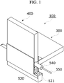
- FIG. 4 is a front view illustrating a supplying case and a withdrawing case of the automatic hair transplant apparatus according to one embodiment of the present invention
- FIGS. 5A and 5B are side views illustrating a case which forms the automatic hair transplant apparatus according to one embodiment of the present invention.
- FIGS. 6 and 7 are views illustrating states in which the automatic hair transplant apparatus according to one embodiment of the present invention is used.
- FIG. 1 is a perspective view of an automatic hair transplant apparatus according to one embodiment of the present invention.
- FIG. 2 is a separate-perspective view of the automatic hair transplant apparatus according to one embodiment of the present invention.
- FIGS. 3A and 3B are views illustrating operation states of a needle module which forms the automatic hair transplant apparatus according to one embodiment of the present invention.
- FIG. 4 is a front view illustrating a supplying case and a withdrawing case of the automatic hair transplant apparatus according to one embodiment of the present invention.
- FIGS. 5A and 5B are side views illustrating a case which forms the automatic hair transplant apparatus according to one embodiment of the present invention.
- An automatic hair transplant apparatus 100 includes a needle module 200 , a supplying case 300 , a withdrawing case 400 , and a hair transplanter 500 .
- a hair follicle H is inserted into the needle module 200 .
- the needle module 200 includes a needle 210 formed in a hollow shape with an inclined or pointed front end 212 , a front end fixing device 220 having a hollow shape and inserted into the front end 212 of the needle 210 , a rear end fixing device 230 having a hollow shape and fixedly coupled to the other end 214 of the needle 210 , and a spring 240 mounted on an outer surface of the needle 210 and located between the front end fixing device 220 and the rear end fixing device 230 .
- the front end fixing device 220 and the rear end fixing device 230 have the same diameters to smoothly move and operate, and a front end of the spring 240 is fixed to the front end fixing device 220 .
- the needle module 200 maintains its initial state due to an elasticity of the spring 240 , and the spring 240 is compressed and the needle 210 is moved toward a scalp when the rear end fixing device 230 is pressurized.
- the supplying case 300 is mounted on one side of the hair transplanter 500 , and a plurality of such needle modules 200 are mounted therein.
- the supplying case 300 is mounted on the one side of the hair transplanter 500 and sequentially supplies the needle modules 200 mounted therein thereto.
- the supplying case 300 includes a cover 310 in which an accommodation space 312 is formed and an opening 314 is formed at a bottom or top thereof, a pressurizing spring 320 inserted into the accommodation space 312 and located opposite the opening 314 of the cover 310 , and a support plate 330 mounted in the accommodation space 312 and located between the pressurizing spring 320 and the opening 314 .
- a module guide groove 316 is formed at a front end of the cover 310 in a longitudinal direction to prevent damage to the needle 210 of the needle module 200 .
- the pressurizing spring 320 and the support plate 330 are sequentially mounted in the cover 310 which includes the accommodation space 312 formed therein, the opening 314 formed at the bottom or top thereof, and the module guide groove 316 formed at the front end in the longitudinal direction.
- the supplying case 300 is formed in a magazine shape into which the needle module 200 is inserted like a bullet of a gun.
- an opening and closing portion 340 which closes and opens the accommodation space 312 may be further included in the opening 314 of the cover 310 .
- the opening and closing portion 340 includes an opening and closing case 342 mounted at a central part of both sides of the cover 310 and having an open bottom, a curved guide 344 having a curved shape and disposed on each of both sides of the opening 314 and located partially in the opening and closing case 342 , and an opening and closing spring 346 disposed at an end of the curved guide 344 and in the opening and closing case 342 .
- the curved guide 344 usually blocks the opening 314 due to an elasticity of the opening and closing spring 346 , and the curved guide 344 is inserted into the opening and closing case 342 and the opening 314 is opened when an external force greater than the elasticity of the opening and closing spring 346 is transferred to an end of the curved guide 344 on an opposite side.
- the withdrawing case 400 is mounted on the other side of the hair transplanter 500 , and a plurality of such needle modules 200 from which hair follicles H are removed are mounted therein.
- the withdrawing case 400 is mounted on the other side of the hair transplanter 500 and sequentially accommodates the needle modules 200 from which the hair follicles H are removed according to an operation of the hair transplanter 500 .
- the withdrawing case 400 includes a cover 410 in which an accommodation space 412 is formed and an opening 414 is formed at a bottom or top thereof, a pressurizing spring 420 inserted into the accommodation space 412 and located opposite the opening 414 of the cover 410 , and a support plate 430 mounted in the accommodation space 412 and located between the pressurizing spring 420 and the opening 414 .
- a module guide groove 416 is formed at a front end of the cover 410 in a longitudinal direction to prevent damage to the needle 210 of the needle module 200 .
- the pressurizing spring 420 and the support plate 430 are sequentially mounted in the cover 410 which includes the accommodation space 412 formed therein, the opening 414 formed at the bottom or top thereof, and the module guide groove 416 formed at the front end in the longitudinal direction.
- the withdrawing case 400 like the supplying case 300 , is formed in a magazine shape in which the needle module 200 is inserted like a bullet of a gun.
- the supplying case 300 and the withdrawing case 400 are mounted on the hair transplanter 500 .
- the hair transplanter 500 sequentially operates the needle modules 200 inserted into the supplying case 300 one by one to transplant the hair follicles H into the scalp, and inserts the needle modules 200 , from which the hair follicles H are removed, into the withdrawing case 400 .
- the hair transplanter 500 includes a hair transplanter case 510 in which a withdrawing case mounting groove 512 and a body mounting groove 514 are collinearly formed and a supplying case mounting groove 516 is rectilinearly or obliquely formed between the withdrawing case mounting groove 512 and the body mounting groove 514 , a body 520 which is mounted on the body mounting groove 514 , linearly moves, and includes a roller guide groove 521 formed at a rear thereof, a moving device 530 formed of any one or a combination of a roller, a ball, an opening, and a bearing mounted on the roller guide groove 521 of the body 520 , a main shaft 540 which has a hollow shape and an outer surface to which a connecting rod 542 , which has one end coupled to the moving device 530 , is fixedly coupled, and a pressurizing bar 550 which is inserted into the main shaft 540 and pressurizes and transplants the hair follicle H into the scalp.
- the withdrawing case 400 is mounted on the withdrawing case mounting groove 512 of the hair transplanter case 510
- the body is mounted on the body mounting groove 514
- the supplying case 300 is mounted on the supplying case mounting groove 516 .
- the needle module 200 with the hair follicle H mounted therein and supplied to the supplying case 300 is moved using the moving device 530 and the main shaft 540 .
- the hair follicle H is transplanted into the scalp using the pressurizing bar 550 .
- the moving device 530 , the main shaft 540 , and the pressurizing bar 550 are allowed to return to their original states.
- the needle module 200 from which the hair follicle H is removed is transferred to the withdrawing case 400 by the body 520 being operated.
- the new needle module 200 in which the hair follicle H is mounted is prepared using the supplying case 300 .
- the roller guide groove 521 formed at the body 520 includes a linear portion 522 formed therein and an inclined portion 523 formed at a rear end for a smooth movement and a peripheral disposition of the main shaft 540 according to the operation of the moving device 530 .
- the moving device 530 and the main shaft 540 move along the inclined portion 523 and the linear portion 522 while the hair follicle H is inserted into the scalp, and move along the linear portion 522 and the inclined portion 523 while the needle module 200 is withdrawn therefrom.
- a plurality of such needle modules 200 which each include the needle 210 formed in a hollow shape with the inclined or pointed front end 212 , the front end fixing device 220 having a hollow shape and inserted into the front end 212 of the needle 210 , the rear end fixing device 230 having a hollow shape and fixedly coupled to the other end 214 of the needle 210 , and the spring 240 mounted on the outer surface of the needle 210 and located between the front end fixing device 220 and the rear end fixing device 230 , are formed.
- the supplying case 300 which includes the cover 310 in which the accommodation space 312 is formed and the opening 314 is formed at the bottom or top thereof, the pressurizing spring 320 inserted into the accommodation space 312 and located opposite the opening 314 of the cover 310 , and the support plate 330 mounted in the accommodation space 312 and located between the pressurizing spring 320 and the opening 314 , is formed.
- the withdrawing case 400 which includes the cover 410 in which the accommodation space 412 is formed and the opening 414 is formed at the bottom or top thereof, the pressurizing spring 420 inserted into the accommodation space 412 and located opposite the opening 414 of the cover 410 , and the support plate 430 mounted in the accommodation space 412 and located between the pressurizing spring 420 and the opening 414 , is formed.
- the hair transplanter 500 which includes the hair transplanter case 510 in which the withdrawing case mounting groove 512 and the body mounting groove 514 are collinearly formed and the supplying case mounting groove 516 is rectilinearly or obliquely formed between the withdrawing case mounting groove 512 and the body mounting groove 514 , the body 520 which is mounted on the body mounting groove 514 , linearly moves, and includes the roller guide groove 521 formed at the rear thereof, the moving device 530 formed of any one or a combination of a roller, a ball, an opening, and a bearing mounted on the roller guide groove 521 of the body 520 , the main shaft 540 which has the hollow shape and the outer surface to which the connecting rod 542 with one end coupled to the moving device 530 is fixedly coupled, and the pressurizing bar 550 which is inserted into the main shaft 540 and pressurizes and transplants the hair follicle H into the scalp, is formed.
- the plurality of needle modules 200 in which the hair follicles H are mounted are mounted in the accommodation space 312 of the supplying case 300 , and then the supplying case 300 in which the plurality of needle modules 200 are provided is mounted on the supplying case mounting groove 516 of the hair transplanter.
- the automatic hair transplant apparatus 100 is completely assembled.
- the assembly order of the automatic hair transplant apparatus may differ from the above description.
- other components in addition to the above-described components may be configured by selecting well-known components of a hair transplant apparatus, and additional descriptions thereof will be omitted.
- the opening 314 is opened by the opening and closing portion 340 of the supplying case 300 being operated, and the needle module 200 in which the hair follicle H is mounted and which is mounted therein is moved to an operation position.
- the needle module 200 in which the hair follicle H is mounted is moved forward and pushed toward the scalp according to operations of the body 520 , the moving device 530 , and the main shaft 540 of the hair transplanter 500 .
- the moving device 530 the main shaft 540 , and the pressurizing bar 550 remain in a state of being moved toward the front end.
- the body 520 is linearly moved to transfer the needle module 200 from which the hair follicle H is removed to the accommodation space 412 of the withdrawing case 400 .
- the moving device 530 and the main shaft 540 are moved to the inclined portion 523 of the roller guide groove 521 .
- the withdrawing case 400 is separated and then the hair follicles H are mounted in the needle modules 200 of the withdrawing case 400 .
- an automatic hair transplant apparatus includes a needle module in which a hair follicle is inserted and a case in which the needle module is mounted, which are configured to be a magazine structure, and thus not only may hair follicles be easily and continuously transplanted but also an operation time may be reduced according thereto.
Landscapes
- Health & Medical Sciences (AREA)
- Surgery (AREA)
- Life Sciences & Earth Sciences (AREA)
- Medical Informatics (AREA)
- Nuclear Medicine, Radiotherapy & Molecular Imaging (AREA)
- Engineering & Computer Science (AREA)
- Biomedical Technology (AREA)
- Heart & Thoracic Surgery (AREA)
- Pathology (AREA)
- Molecular Biology (AREA)
- Animal Behavior & Ethology (AREA)
- General Health & Medical Sciences (AREA)
- Public Health (AREA)
- Veterinary Medicine (AREA)
- Surgical Instruments (AREA)
- Prostheses (AREA)
Abstract
Description
Claims (11)
Applications Claiming Priority (4)
| Application Number | Priority Date | Filing Date | Title |
|---|---|---|---|
| KR10-2017-0003468 | 2017-01-10 | ||
| KR20170003468 | 2017-01-10 | ||
| KR10-2017-0172441 | 2017-12-14 | ||
| KR1020170172441A KR102527392B1 (en) | 2017-01-10 | 2017-12-14 | Automatic implanting apparatus |
Publications (2)
| Publication Number | Publication Date |
|---|---|
| US20180193058A1 US20180193058A1 (en) | 2018-07-12 |
| US10695090B2 true US10695090B2 (en) | 2020-06-30 |
Family
ID=62782505
Family Applications (1)
| Application Number | Title | Priority Date | Filing Date |
|---|---|---|---|
| US15/867,352 Active 2038-10-01 US10695090B2 (en) | 2017-01-10 | 2018-01-10 | Automatic hair transplant apparatus |
Country Status (1)
| Country | Link |
|---|---|
| US (1) | US10695090B2 (en) |
Families Citing this family (2)
| Publication number | Priority date | Publication date | Assignee | Title |
|---|---|---|---|---|
| KR102271869B1 (en) * | 2015-11-12 | 2021-07-05 | 한국전자통신연구원 | apparatus to load follicular unit into needle for hair implant |
| CN115245353B (en) * | 2022-07-12 | 2023-02-21 | 北京碧莲盛不剃发植发医疗美容门诊部有限责任公司 | Sawtooth hair taking device based on no-shaving technology |
Citations (6)
| Publication number | Priority date | Publication date | Assignee | Title |
|---|---|---|---|---|
| US5439475A (en) * | 1990-07-03 | 1995-08-08 | Bennett; David M. | Tissue grafting method using an apparatus with multiple tissue receiving receptacles |
| KR200470718Y1 (en) | 2013-10-28 | 2014-01-07 | 공동현 | Hair transplanter |
| US8753354B2 (en) * | 2004-03-09 | 2014-06-17 | John P. Cole | Enhanced follicular extraction punch and method |
| US20160015424A1 (en) | 2014-07-18 | 2016-01-21 | Electronics And Telecommunications Research Institute | Apparatus and method for loading follicles |
| US20160045223A1 (en) | 2014-08-14 | 2016-02-18 | Electronics And Telecommunications Research Institute | Injector for hair implant with automatic follicle supply function |
| KR20160142691A (en) | 2015-06-03 | 2016-12-13 | 주식회사 오성전자 | Automatic implanting apparatus |
-
2018
- 2018-01-10 US US15/867,352 patent/US10695090B2/en active Active
Patent Citations (6)
| Publication number | Priority date | Publication date | Assignee | Title |
|---|---|---|---|---|
| US5439475A (en) * | 1990-07-03 | 1995-08-08 | Bennett; David M. | Tissue grafting method using an apparatus with multiple tissue receiving receptacles |
| US8753354B2 (en) * | 2004-03-09 | 2014-06-17 | John P. Cole | Enhanced follicular extraction punch and method |
| KR200470718Y1 (en) | 2013-10-28 | 2014-01-07 | 공동현 | Hair transplanter |
| US20160015424A1 (en) | 2014-07-18 | 2016-01-21 | Electronics And Telecommunications Research Institute | Apparatus and method for loading follicles |
| US20160045223A1 (en) | 2014-08-14 | 2016-02-18 | Electronics And Telecommunications Research Institute | Injector for hair implant with automatic follicle supply function |
| KR20160142691A (en) | 2015-06-03 | 2016-12-13 | 주식회사 오성전자 | Automatic implanting apparatus |
Also Published As
| Publication number | Publication date |
|---|---|
| US20180193058A1 (en) | 2018-07-12 |
Similar Documents
| Publication | Publication Date | Title |
|---|---|---|
| US10695090B2 (en) | Automatic hair transplant apparatus | |
| US12226096B2 (en) | Tissue anchor handling systems and methods | |
| US10441315B2 (en) | Apparatus for loading follicular unit into needle for hair implant | |
| RU2145820C1 (en) | Apparatus for mechanical implantation of hair roots in individual's skin by introducing transplants | |
| US20200155300A1 (en) | Automatic hair implant apparatus | |
| JP6449018B2 (en) | Device for driving articulating probe | |
| EP3298927B1 (en) | Slide device | |
| US20160015424A1 (en) | Apparatus and method for loading follicles | |
| CN101422400A (en) | Intraocular lens injection instrument | |
| US20130285527A1 (en) | Refrigerator and handle assembly method thereof | |
| EP1984063B1 (en) | Kit for and method of assembling an applicator for inserting an implant | |
| CN105627681A (en) | Refrigerator | |
| US10251674B2 (en) | Manual follicle-transplanting hair transplanter for increasing graft survival rate | |
| KR102527393B1 (en) | Automatic hair implanter | |
| KR20210024159A (en) | Conveying device | |
| CN212234612U (en) | Automatic particle implantation device | |
| US20170020565A1 (en) | Automatic hair transplanter for transplanting follicles | |
| US20220133353A1 (en) | Hair transplanter having core shaft conveying portion | |
| KR102527392B1 (en) | Automatic implanting apparatus | |
| KR102425251B1 (en) | Automatic implanting apparatus | |
| CN110786973B (en) | Assembly, conveyor and system for controlling release of an implantation instrument | |
| CN202607683U (en) | Art knife | |
| CN215503598U (en) | Stent delivery device | |
| US11221193B2 (en) | Firearm accessory and method thereof | |
| JP2020115974A (en) | Stent storage aid |
Legal Events
| Date | Code | Title | Description |
|---|---|---|---|
| FEPP | Fee payment procedure |
Free format text: ENTITY STATUS SET TO UNDISCOUNTED (ORIGINAL EVENT CODE: BIG.); ENTITY STATUS OF PATENT OWNER: SMALL ENTITY |
|
| AS | Assignment |
Owner name: ELECTRONICS AND TELECOMMUNICATIONS RESEARCH INSTITUTE, KOREA, REPUBLIC OF Free format text: ASSIGNMENT OF ASSIGNORS INTEREST;ASSIGNORS:BAE, TAE WUK;JUNG, YONG CHUL;KIM, MOON KYU;AND OTHERS;REEL/FRAME:044603/0566 Effective date: 20180108 Owner name: ELECTRONICS AND TELECOMMUNICATIONS RESEARCH INSTIT Free format text: ASSIGNMENT OF ASSIGNORS INTEREST;ASSIGNORS:BAE, TAE WUK;JUNG, YONG CHUL;KIM, MOON KYU;AND OTHERS;REEL/FRAME:044603/0566 Effective date: 20180108 |
|
| AS | Assignment |
Owner name: KYUNGPOOK NATIONAL UNIVERSITY INDUSTRY-ACADEMIC COOPERATION FOUNDATION, KOREA, REPUBLIC OF Free format text: ASSIGNMENT OF ASSIGNORS INTEREST;ASSIGNORS:BAE, TAE WUK;JUNG, YONG CHUL;KIM, MOON KYU;AND OTHERS;REEL/FRAME:044693/0370 Effective date: 20180118 Owner name: ELECTRONICS AND TELECOMMUNICATIONS RESEARCH INSTITUTE, KOREA, REPUBLIC OF Free format text: ASSIGNMENT OF ASSIGNORS INTEREST;ASSIGNORS:BAE, TAE WUK;JUNG, YONG CHUL;KIM, MOON KYU;AND OTHERS;REEL/FRAME:044693/0370 Effective date: 20180118 Owner name: ELECTRONICS AND TELECOMMUNICATIONS RESEARCH INSTIT Free format text: ASSIGNMENT OF ASSIGNORS INTEREST;ASSIGNORS:BAE, TAE WUK;JUNG, YONG CHUL;KIM, MOON KYU;AND OTHERS;REEL/FRAME:044693/0370 Effective date: 20180118 Owner name: KYUNGPOOK NATIONAL UNIVERSITY INDUSTRY-ACADEMIC CO Free format text: ASSIGNMENT OF ASSIGNORS INTEREST;ASSIGNORS:BAE, TAE WUK;JUNG, YONG CHUL;KIM, MOON KYU;AND OTHERS;REEL/FRAME:044693/0370 Effective date: 20180118 |
|
| FEPP | Fee payment procedure |
Free format text: ENTITY STATUS SET TO SMALL (ORIGINAL EVENT CODE: SMAL); ENTITY STATUS OF PATENT OWNER: SMALL ENTITY |
|
| STPP | Information on status: patent application and granting procedure in general |
Free format text: DOCKETED NEW CASE - READY FOR EXAMINATION |
|
| STPP | Information on status: patent application and granting procedure in general |
Free format text: NON FINAL ACTION MAILED |
|
| STPP | Information on status: patent application and granting procedure in general |
Free format text: RESPONSE TO NON-FINAL OFFICE ACTION ENTERED AND FORWARDED TO EXAMINER |
|
| STCF | Information on status: patent grant |
Free format text: PATENTED CASE |
|
| MAFP | Maintenance fee payment |
Free format text: PAYMENT OF MAINTENANCE FEE, 4TH YR, SMALL ENTITY (ORIGINAL EVENT CODE: M2551); ENTITY STATUS OF PATENT OWNER: SMALL ENTITY Year of fee payment: 4 |