US10695075B2 - Handheld surgical device having retractable portion - Google Patents
Handheld surgical device having retractable portion Download PDFInfo
- Publication number
- US10695075B2 US10695075B2 US15/400,476 US201715400476A US10695075B2 US 10695075 B2 US10695075 B2 US 10695075B2 US 201715400476 A US201715400476 A US 201715400476A US 10695075 B2 US10695075 B2 US 10695075B2
- Authority
- US
- United States
- Prior art keywords
- surgical device
- working portion
- handheld surgical
- shroud
- cutting blade
- Prior art date
- Legal status (The legal status is an assumption and is not a legal conclusion. Google has not performed a legal analysis and makes no representation as to the accuracy of the status listed.)
- Expired - Fee Related, expires
Links
Images


Classifications
-
- A—HUMAN NECESSITIES
- A61—MEDICAL OR VETERINARY SCIENCE; HYGIENE
- A61B—DIAGNOSIS; SURGERY; IDENTIFICATION
- A61B17/00—Surgical instruments, devices or methods
- A61B17/32—Surgical cutting instruments
- A61B17/3205—Excision instruments
-
- A—HUMAN NECESSITIES
- A61—MEDICAL OR VETERINARY SCIENCE; HYGIENE
- A61B—DIAGNOSIS; SURGERY; IDENTIFICATION
- A61B17/00—Surgical instruments, devices or methods
- A61B17/16—Instruments for performing osteoclasis; Drills or chisels for bones; Trepans
- A61B17/1613—Component parts
- A61B17/1633—Sleeves, i.e. non-rotating parts surrounding the bit shaft, e.g. the sleeve forming a single unit with the bit shaft
-
- A—HUMAN NECESSITIES
- A61—MEDICAL OR VETERINARY SCIENCE; HYGIENE
- A61B—DIAGNOSIS; SURGERY; IDENTIFICATION
- A61B17/00—Surgical instruments, devices or methods
- A61B17/16—Instruments for performing osteoclasis; Drills or chisels for bones; Trepans
- A61B17/1613—Component parts
- A61B17/1615—Drill bits, i.e. rotating tools extending from a handpiece to contact the worked material
-
- A—HUMAN NECESSITIES
- A61—MEDICAL OR VETERINARY SCIENCE; HYGIENE
- A61B—DIAGNOSIS; SURGERY; IDENTIFICATION
- A61B17/00—Surgical instruments, devices or methods
- A61B17/16—Instruments for performing osteoclasis; Drills or chisels for bones; Trepans
- A61B17/1613—Component parts
- A61B17/1622—Drill handpieces
-
- A—HUMAN NECESSITIES
- A61—MEDICAL OR VETERINARY SCIENCE; HYGIENE
- A61B—DIAGNOSIS; SURGERY; IDENTIFICATION
- A61B17/00—Surgical instruments, devices or methods
- A61B17/32—Surgical cutting instruments
- A61B17/320016—Endoscopic cutting instruments, e.g. arthroscopes, resectoscopes
- A61B17/32002—Endoscopic cutting instruments, e.g. arthroscopes, resectoscopes with continuously rotating, oscillating or reciprocating cutting instruments
-
- A—HUMAN NECESSITIES
- A61—MEDICAL OR VETERINARY SCIENCE; HYGIENE
- A61B—DIAGNOSIS; SURGERY; IDENTIFICATION
- A61B17/00—Surgical instruments, devices or methods
- A61B17/32—Surgical cutting instruments
- A61B17/3205—Excision instruments
- A61B17/3207—Atherectomy devices working by cutting or abrading; Similar devices specially adapted for non-vascular obstructions
- A61B17/320708—Curettes, e.g. hollow scraping instruments
-
- A—HUMAN NECESSITIES
- A61—MEDICAL OR VETERINARY SCIENCE; HYGIENE
- A61B—DIAGNOSIS; SURGERY; IDENTIFICATION
- A61B17/00—Surgical instruments, devices or methods
- A61B17/00234—Surgical instruments, devices or methods for minimally invasive surgery
- A61B2017/00353—Surgical instruments, devices or methods for minimally invasive surgery one mechanical instrument performing multiple functions, e.g. cutting and grasping
-
- A—HUMAN NECESSITIES
- A61—MEDICAL OR VETERINARY SCIENCE; HYGIENE
- A61B—DIAGNOSIS; SURGERY; IDENTIFICATION
- A61B17/00—Surgical instruments, devices or methods
- A61B2017/00367—Details of actuation of instruments, e.g. relations between pushing buttons, or the like, and activation of the tool, working tip, or the like
-
- A—HUMAN NECESSITIES
- A61—MEDICAL OR VETERINARY SCIENCE; HYGIENE
- A61B—DIAGNOSIS; SURGERY; IDENTIFICATION
- A61B17/00—Surgical instruments, devices or methods
- A61B2017/00982—General structural features
- A61B2017/00991—Telescopic means
-
- A—HUMAN NECESSITIES
- A61—MEDICAL OR VETERINARY SCIENCE; HYGIENE
- A61B—DIAGNOSIS; SURGERY; IDENTIFICATION
- A61B17/00—Surgical instruments, devices or methods
- A61B17/32—Surgical cutting instruments
- A61B2017/320052—Guides for cutting instruments
-
- A—HUMAN NECESSITIES
- A61—MEDICAL OR VETERINARY SCIENCE; HYGIENE
- A61B—DIAGNOSIS; SURGERY; IDENTIFICATION
- A61B17/00—Surgical instruments, devices or methods
- A61B17/32—Surgical cutting instruments
- A61B17/320068—Surgical cutting instruments using mechanical vibrations, e.g. ultrasonic
- A61B2017/320072—Working tips with special features, e.g. extending parts
-
- A—HUMAN NECESSITIES
- A61—MEDICAL OR VETERINARY SCIENCE; HYGIENE
- A61B—DIAGNOSIS; SURGERY; IDENTIFICATION
- A61B90/00—Instruments, implements or accessories specially adapted for surgery or diagnosis and not covered by any of the groups A61B1/00 - A61B50/00, e.g. for luxation treatment or for protecting wound edges
- A61B90/08—Accessories or related features not otherwise provided for
- A61B2090/0801—Prevention of accidental cutting or pricking
- A61B2090/08021—Prevention of accidental cutting or pricking of the patient or his organs
Definitions
- This disclosure relates generally to a handheld surgical device configured for performing one or more surgical procedure(s).
- Surgical tools are used in the healthcare field to, for example, affect (e.g., cut, remove, cauterize, etc.) an anatomical part during a surgical procedure.
- each surgical tool is configured to perform a specific function. Accordingly, it can be necessary for a professional to use multiple surgical tools during a surgical procedure when different functions are needed to complete the surgical procedure.
- the inventor has discovered that when a professional uses multiple surgical tools, manual actions of switching between the two surgical tools can be very time consuming, and can lead to increase in associated costs.
- the disclosure herein provides improved handheld surgical devices and methods related to the handheld surgical devices.
- Some of the embodiments of the handheld surgical devices described herein are configured with a working portion that is covered (e.g., when not being used), and then uncovered (e.g., when it is being used).
- the working portion can be retracted to be covered when it is not being used, but then the working portion is extended to be uncovered when it is being used.
- the part that covers the working portion can include another working portion that is configured for performing a different procedure.
- some of the embodiments of the handheld surgical devices can be used to perform two or more specific functions.
- the embodiments of the handheld surgical devices described herein can reduce and/or eliminate the need for switching between surgical devices during performance of a surgical procedure. Thus, there can be savings in time, related costs, or both.
- the handheld surgical device has a distal portion and a proximal portion.
- proximal and distal are used herein to indicate portions of the handheld surgical device with respect to an operator's hand. That is, the proximal portion is close to the operator's hand than the distal portion of the handheld surgical device.
- the proximal portion includes a handle configured for being held by an operator's hand.
- a switch is disposed at the proximal portion (e.g., handle), and the switch is configured to operate the distal portion so that at least a part of the distal portion covers the working portion.
- the switch can also be configured operate the distal portion to uncover the working portion.
- a single switch can be configured to have two stages, wherein in a first stage, the switch advances the working portion at the distal portion so that the working portion becomes uncovered.
- the uncovered working portion allows the operator to operate the handheld surgical device to perform a function which the working portion is configured to perform (e.g., drill bone, cut tissue, etc.)
- the switch retracts the working portion at the distal portion so that the working portion becomes covered.
- the covered working portion prevents the operator from operating the handheld surgical device to perform the function of the working portion.
- the working portion cannot be used by the operator.
- a different portion can be used by the operator to perform a different function.
- another portion of the handheld surgical device is configured to protect nearby anatomical part(s) when the uncovered working portion is being used by the operator.
- the working portion includes a cutting blade.
- the cutting blade can be configured for cutting soft tissue, but not bone.
- the working portion includes a drill.
- the drill can be configured for cutting bone, drilling into bone, or both.
- the working portion is driven by a motor disposed at the proximal portion connected to a power supply.
- the distal portion of the handheld surgical device which covers the working portion includes a shroud.
- the shroud and/or a part of the distal portion includes a cutting edge, wherein the cutting edge is configured to perform a function that is different from the working portion.
- the cutting edge is configured for cutting soft tissue.
- the working portion is driven by a motor to cut and/or drill bone.
- the cutting edge is operable by manual movement of the operator, and the cutting edge is not driven by a motor.
- FIG. 1 shows a schematic illustration of an embodiment of the handheld surgical device.
- FIGS. 2A and 2B show schematic side views of an embodiment of the handheld surgical device.
- FIG. 3 shows a flowchart of an embodiment of a method of using the handheld surgical device.
- FIG. 4 shows a schematic side view of another embodiment of the handheld surgical device.
- FIG. 5 shows a schematic top view of a portion of the distal portion of the handheld surgical device shown in FIG. 4 .
- FIG. 6 shows a schematic side view of another embodiment of the handheld surgical device.
- a working portion of a handheld surgical device is configured for performing a specific function during a medical procedure that is performed by a healthcare professional.
- a medical procedure it can be necessary for the healthcare profession to switch between different handheld surgical devices at the same or near an anatomical location, such as a wound.
- an anatomical location such as a wound.
- a device for cutting and removing soft tissue may be used, and then, when that device nears a bone, a different device may be needed to cut away the bone. Switching between different handheld surgical devices repeatedly within the wound to complete an operation can increase the operation time and associated costs.
- switching between different surgical devices may require the healthcare professional to take her eyes off of the anatomical region (e.g., wound) and also may require additional mental concentration in order to acquire the correct tool for the needed function in the anatomical region. Accordingly, alternating between several tools can be tedious and may increase the fatigue of the healthcare professional, risk of contamination, infection, and/or damage to the patient. The contamination, infection, and/or intended damage can cause or exacerbate problems for a patient and a treatment plan. Thus, there is a clear advantage for a handheld surgical device which can reduce and/or eliminate the tedious alternation between different tools.
- the handheld surgical devices described herein can provide multiple tools and/or functions in a single device. Thus, the handheld surgical devices described herein can reduce and/or eliminate the tedious alternation between different tools.
- An embodiment of a handheld surgical device described herein includes a shroud that extends from a working portion disposed on a distal portion and a cutting blade within a neck portion of the distal portion, from which the cutting blade can be retracted and advanced based on the setting of a switch.
- the shroud portion of the handheld surgical device can include a cup portion that can function independently of the cutting blade.
- FIG. 1 shows a schematic illustration of a handheld surgical device 100 , according to an embodiment.
- the handheld surgical device 100 includes a proximal portion 102 and a distal portion 104 .
- the proximal portion 102 includes a handle 106 configured for a user's hand to hold, preferably comfortably, while the handheld surgical device 100 is being used.
- the distal portion 104 includes a working portion 108 . At least a part of the working portion 108 is configured for being inserted into a wound or an anatomical area to perform a function (e.g., drill bone, cut tissue, etc.) during a surgical procedure.
- a function e.g., drill bone, cut tissue, etc.
- the distal portion 104 can be attached and/or detached from the proximal portion 102 at an attachment region 110 .
- the distal portion 104 can be detached from the proximal portion 102 at the attachment region 110 after use in a surgical procedure, and then a new (i.e., unused) distal portion 104 can be attached to the proximal portion 102 at the attachment region 110 before being used in another surgical procedure.
- the distal portion 104 can be removed and cleaned/sanitized before being reattached to the proximal portion 102 for future use. That is, the distal portions 104 can be disposed of after use, or be sanitized after use for reuse.
- the distal portion 104 includes a neck portion 112 , which extends from the attachment region 110 to the working portion 108 .
- the working portion 108 of the handheld surgical device 100 can be covered by a shroud 114 (or a cover) disposed at or near the end of the distal portion 104 .
- the shroud 114 can be, for example, cup-shaped and have a cutting edge 116 .
- the shroud 114 can be a concave shaped portion, a hooded cover, or be a partially enclosed scoop.
- the shroud 114 can be configured for cutting and/or scooping soft tissue, without requiring a powered motor, while the working portion 108 is connected to a motor and a power supply so that the motor drive the working portion 108 so that the working portion 108 can cut or drill into hard tissue and/or bone.
- a healthcare professional can use the handheld surgical device 100 for at least two different functions (e.g., for affecting different anatomical regions).
- the handheld surgical device 100 can eliminate the need for manually switching between two different surgical tools (e.g., for cutting soft tissue and for cutting bone) during a surgical procedure.
- the working portion 108 can be uncovered by the shroud 114 by, for example, being extended outward from the shroud 114 .
- the proximal portion 102 of the handheld surgical device 100 includes a switch 118 disposed at or near the handle 106 , wherein the switch 118 can include a first setting for uncovering the working portion 108 and a second setting for covering the working portion 108 .
- the length of the working portion 108 is at least 0.5 mm. In some embodiments, the length of the working portion 108 is at least 1.0 mm. In some embodiments, the length of the working portion 108 is at most 10.0 mm. In some embodiments, the length of the working portion 108 can be approximately from 0.5 mm to 10 mm. In some embodiments, the length of the working portion 108 can be approximately from 1 mm to 10 mm.
- the handheld surgical device 100 can be of various shapes and sizes.
- FIGS. 2A and 2B illustrate schematic side views of a handheld surgical device 200 , according to an embodiment.
- the handheld surgical device 200 includes a proximal portion 202 , a distal portion 204 , a handle 206 , a working portion 208 , an attachment region 210 , a neck portion 212 , a shroud 214 , a cutting edge 216 , and a switch 218 , wherein these elements are similar to the like features shown and described with respect to FIG. 1 .
- the proximal portion 202 includes a mechanism 220 that is connected to the switch 218 and to the working portion 208 , wherein the mechanism 220 is configured to change the position of the working portion 208 (e.g., extended position or retracted position) based in a user's input via the switch 218 .
- the working portion 208 includes a cutting blade 222 driven by a motor 224 that is powered by a power supply 226 .
- the motor 224 and the power supply 226 are disposed in the proximal portion 202 .
- Another switch 228 is configured to activate the motor 224 to drive the cutting blade 222 .
- FIG. 2A shows the working portion 208 in the retracted position (operable by the switch 218 ), wherein the working portion 208 is substantially disposed inside a cavity 230 in the neck portion 212 . This allows for the cutting edge 216 to be used (e.g., for cutting soft tissue) without being hindered by the working portion 208 .
- FIG. 2B shows the cutting blade 222 and/or the working portion 208 in the extended position (operable by the switch 218 ), wherein the cutting blade 222 and/or the working portion 208 is extended out of the cavity 230 and positioned distally away from the cutting edge 216 .
- This allows for the cutting blade 222 and/or the working portion 208 to be used (e.g., for cutting bone) without being hindered by the cutting edge 216 .
- the shroud 214 is disposed at a location away from the cutting blade 222 and/or the working portion 208 , so that the shroud 214 can be used to shield and/or protect an anatomical region when the working portion 208 is being used.
- the position of the shroud 214 with respect to the extended cutting blade 222 and/or extended working portion 208 provides the shroud 214 to be used for pushing away tissue or other anatomical regions that the user does not desire to be affected (e.g., cut, drill, etc.) by the extended cutting blade 222 and/or the extended working portion 208 .
- the cutting blade 222 can be a cutting burr made composed of diamond, carbide or like material, and having an oval, matchstick, pear, twist drill, a fluted ball, or the like shape. In some embodiments, the cutting blade 222 can take the shape and/or components of traditional burrs.
- the cutting edge 216 of the shroud 214 can function.
- the shroud 214 has a cup-like shape (e.g., scoop-shaped)
- the shroud 214 can be used to scoop and/or gather tissue, bone, blood, and/or the like during the surgical procedure.
- the cutting edge 216 can function to cut soft tissue, soft bone, and/or a line during the surgical procedure. Because the cutting edge 216 is not powered by a motor, the cutting edge 216 can function to cut soft tissue and/or soft bone. However, the cutting blade 222 , which is driven by a motor, can function to cut harder tissue and/or bone.
- the power supply 226 can be a battery, a unit for converting AC to DC with a cord for connecting to an AC source, an air pressure unit (i.e., the motor is driven by pressurized air or suction), etc.
- the power supply 226 can power the motor 224 , which can cause the cutting blade 222 to rotate.
- the cutting blade 222 can rotate at speeds capable of cutting through tissue, bone, or the like during a surgical procedure.
- FIG. 3 illustrates a method flow diagram 300 for using the handheld surgical device, according to an embodiment.
- a user connects a proximal portion (e.g., 202 shown in FIG. 2A ) and a distal portion (e.g., 204 shown in FIG. 2A ) of the handheld surgical device (e.g., 200 shown in FIG. 2A ).
- This step 302 can include attaching a different (e.g., new) distal portion to the proximal portion and activating a locking mechanism on the proximal portion to lock the distal portion in place.
- the different distal portion can be added and/or detached for each new surgical procedure such that the risk of infection and/or contamination is decreased.
- the user can use the handheld surgical device for cutting tissue, by using a cutting edge or a cutting blade (e.g., the working portion), based on whether the working portion is extended or retracted.
- a cutting edge or a cutting blade e.g., the working portion
- the user can extend or retract the working portion, and then at step 304 , use the handheld surgical device for cutting tissue or bone, by using the cutting edge or the working portion (e.g., the cutting blade).
- the user retracts the working portion so that the working portion is no longer operable, the user can use the handheld surgical device for cutting tissue with the cutting edge.
- Retracting the cutting blade includes disabling the operation to cut a removal portion with the cutting blade.
- retracting the cutting blade completely protects the cutting blade via inside the neck portion of the handheld surgical device. That is, retracting the cutting blade disables the operation to cut a removal portion as it is nestled inside the neck portion of the surgical device and not protected by the shroud, as described herein.
- the cutting blade and/or the working portion can be partially protected by a shroud while enabling an operation to cut a removal portion in the anatomy.
- a removal portion is a portion to be removed and/or cut during a surgical procedure.
- a removal portion can be an area of bone, tissue, blood, or the like.
- the shroud can partially cover the cutting blade so as to protect areas that are not meant to be cut (e.g., non-removal portions).
- Step 306 can include powering a motor connected to the cutting blade such that the cutting blade rotates at a speed capable of cutting bone. That is, power can be provided to a motor associated with the cutting blade such that the cutting blade can rotate and cut the removal portion.
- the user can disconnect the proximal portion and the distal portion. Then the distal portion can be discarded or sanitized for reuse.
- the distal portion can be removed from the proximal portion at an attachment region, as described herein. Disposing of the distal portion can decrease cross-contamination and/or cross-infection between patients receiving surgical procedures. For instance, using a new distal portion for each patient can significantly reduce contamination and infections risks.
- the distal portion can be detached and cleaned before being reattached to the proximal portion. For instance, the distal portion may be detached and cleaned via autoclaving, sanitization procedures, soap, alcohol, and/or the like. The cleaned and/or sanitized distal portion can be reattached to the proximal portion for future use.
- FIG. 3 The steps shown in FIG. 3 can be performed in various sequences and/or combinations.
- the flowchart shown in FIG. 3 provides for performing the steps according to one or more of the exemplary orders and/or sequences listed below (but not necessarily limited only to these orders):
- FIG. 4 shows a schematic side view of another embodiment of the handheld surgical device 400 .
- the handheld surgical device 400 includes a proximal portion 402 , a distal portion 404 , a handle 406 , a working portion 408 , an attachment region 410 , a neck portion 412 , a shroud 414 , a cutting edge 416 , and a switch 418 .
- the proximal portion 402 includes a mechanism 420 that is connected to the switch 418 and to the working portion 408 , wherein the mechanism 420 is configured to change the position of the working portion 408 (e.g., extended position or retracted position) based in a user's input via the switch 418 .
- the working portion 408 includes a cutting blade 422 driven by a motor 424 that is powered by a power supply 426 .
- the motor 424 and the power supply 426 are disposed in the proximal portion 402 .
- Another switch 428 is configured to activate the motor 424 to drive the cutting blade 422 .
- the working portion 408 can be placed in the retracted position (operable by the switch 418 ), wherein the working portion 408 is substantially disposed inside a cavity 430 in the neck portion 412 . This allows for the cutting edge 416 to be used (e.g., for cutting soft tissue) without being hindered by the working portion 408 .
- the shroud 414 shows the cutting blade 422 and/or the working portion 408 in the extended position (operable by the switch 418 ), wherein the cutting blade 422 and/or the working portion 408 is extended out of the cavity 430 and positioned at least partly within a space that is at least partly surrounded by the shroud 414 .
- the shroud 414 is a concave scoop-like configuration, then at least part of the cutting blade 422 and/or the working portion 408 is contained in the concave scoop-like shape, as shown in FIG. 4 .
- the shroud 414 can be used to shield and/or protect an anatomical region when the cutting blade 422 and/or the working portion 408 is being used.
- FIG. 5 A top view of a portion 500 of the distal portion 404 is shown in FIG. 5 .
- the portion 500 when viewed from above, shows the cutting blade 422 and/or the working portion 408 contained in the concave scoop-like shape of the shroud 414 when the working portion 408 is in the extended configuration.
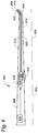
- FIG. 6 shows a schematic side view of another embodiment of the handheld surgical device.
- the handheld surgical device 600 includes a proximal portion 602 , a distal portion 604 , a handle 606 , a working portion 608 , a shaft 610 , a neck portion 612 , a shroud 614 , a cutting edge 616 , and a switch 618 .
- the proximal portion 602 includes a mechanism 620 that is connected to the switch 618 and to the working portion 608 , wherein the mechanism 620 is configured to change the position of the working portion 608 (e.g., extended position or retracted position) based in a user's input via the switch 618 .
- the working portion 608 includes a cutting blade 622 driven by a motor 624 that is powered by a power supply 626 .
- the motor 624 and the power supply 626 are disposed in the proximal portion 602 .
- Another switch 628 is configured to activate the motor 624 to drive the cutting blade 622 .
- the working portion 608 can be placed in the retracted position (operable by the switch 618 ), wherein the working portion 608 is substantially disposed inside a cavity 630 in the neck portion 612 . This allows for the cutting edge 616 to be used (e.g., for cutting soft tissue) without being hindered by the working portion 608 .
- the shroud 614 can be used to shield and/or protect an anatomical region when the cutting blade 622 and/or the working portion 608 is being used.
- the neck portion 612 is at least partly curved.
- the shaft 610 which connects to the working portion 608 and the mechanism 620 and/or the motor 626 , can be configured to be flexible to follow the curved neck portion 612 within the cavity 630 .
- the shaft 610 is not flexible, but is configured to be guided within the cavity 630 of the curved neck portion 612 .
- at least a part of the shaft 610 is flexible so that the cutting blade 622 and/or the working portion 608 can be guided to be within the cavity 630 of the curved neck portion 612 when retracted.
Landscapes
- Health & Medical Sciences (AREA)
- Surgery (AREA)
- Life Sciences & Earth Sciences (AREA)
- Biomedical Technology (AREA)
- Medical Informatics (AREA)
- Veterinary Medicine (AREA)
- Public Health (AREA)
- Engineering & Computer Science (AREA)
- General Health & Medical Sciences (AREA)
- Heart & Thoracic Surgery (AREA)
- Nuclear Medicine, Radiotherapy & Molecular Imaging (AREA)
- Molecular Biology (AREA)
- Animal Behavior & Ethology (AREA)
- Orthopedic Medicine & Surgery (AREA)
- Dentistry (AREA)
- Oral & Maxillofacial Surgery (AREA)
- Vascular Medicine (AREA)
- Surgical Instruments (AREA)
Abstract
Description
-
-
steps -
steps -
steps -
steps -
steps -
steps -
steps -
steps -
steps -
steps -
steps -
steps -
steps -
steps -
steps
-
Claims (10)
Priority Applications (2)
| Application Number | Priority Date | Filing Date | Title |
|---|---|---|---|
| US15/400,476 US10695075B2 (en) | 2016-01-07 | 2017-01-06 | Handheld surgical device having retractable portion |
| US16/905,231 US20200315636A1 (en) | 2016-01-07 | 2020-06-18 | Handheld surgical device having retractable portion |
Applications Claiming Priority (2)
| Application Number | Priority Date | Filing Date | Title |
|---|---|---|---|
| US201662276007P | 2016-01-07 | 2016-01-07 | |
| US15/400,476 US10695075B2 (en) | 2016-01-07 | 2017-01-06 | Handheld surgical device having retractable portion |
Related Child Applications (1)
| Application Number | Title | Priority Date | Filing Date |
|---|---|---|---|
| US16/905,231 Continuation US20200315636A1 (en) | 2016-01-07 | 2020-06-18 | Handheld surgical device having retractable portion |
Publications (2)
| Publication Number | Publication Date |
|---|---|
| US20170196573A1 US20170196573A1 (en) | 2017-07-13 |
| US10695075B2 true US10695075B2 (en) | 2020-06-30 |
Family
ID=59274288
Family Applications (2)
| Application Number | Title | Priority Date | Filing Date |
|---|---|---|---|
| US15/400,476 Expired - Fee Related US10695075B2 (en) | 2016-01-07 | 2017-01-06 | Handheld surgical device having retractable portion |
| US16/905,231 Abandoned US20200315636A1 (en) | 2016-01-07 | 2020-06-18 | Handheld surgical device having retractable portion |
Family Applications After (1)
| Application Number | Title | Priority Date | Filing Date |
|---|---|---|---|
| US16/905,231 Abandoned US20200315636A1 (en) | 2016-01-07 | 2020-06-18 | Handheld surgical device having retractable portion |
Country Status (6)
| Country | Link |
|---|---|
| US (2) | US10695075B2 (en) |
| KR (1) | KR102726371B1 (en) |
| CN (1) | CN108430353B (en) |
| DE (1) | DE112017000316T5 (en) |
| GB (2) | GB2561505B (en) |
| WO (1) | WO2017120467A1 (en) |
Families Citing this family (3)
| Publication number | Priority date | Publication date | Assignee | Title |
|---|---|---|---|---|
| EP3531924A1 (en) * | 2016-10-26 | 2019-09-04 | Michael D. Smith | Handheld surgical device having a rotating portion |
| WO2022098739A1 (en) * | 2020-11-03 | 2022-05-12 | Wildhurst Surgical Technologies, Llc | Handheld surgical device having retractable portion |
| US20250025202A1 (en) * | 2023-07-20 | 2025-01-23 | Linus Ventures Llc | Surgical apparatus |
Citations (17)
| Publication number | Priority date | Publication date | Assignee | Title |
|---|---|---|---|---|
| US3937222A (en) * | 1973-11-09 | 1976-02-10 | Surgical Design Corporation | Surgical instrument employing cutter means |
| US5601583A (en) | 1995-02-15 | 1997-02-11 | Smith & Nephew Endoscopy Inc. | Surgical instrument |
| US20030055404A1 (en) * | 2001-09-17 | 2003-03-20 | Moutafis Timothy E. | Endoscopic rotary abraders |
| US20040191897A1 (en) | 2003-03-31 | 2004-09-30 | The Cleveland Clinic Foundation | Apparatus and method for harvesting bone marrow |
| US20050054972A1 (en) * | 2003-09-09 | 2005-03-10 | Adams Kenneth M. | Surgical micro-burring instrument and method of performing sinus surgery |
| US20050197661A1 (en) * | 2004-03-03 | 2005-09-08 | Scimed Life Systems, Inc. | Tissue removal probe with sliding burr in cutting window |
| US20080183175A1 (en) * | 2007-01-26 | 2008-07-31 | Laurimed Llc | Styli used to position device for carrying out selective discectomy |
| US20080281343A1 (en) | 2006-05-30 | 2008-11-13 | Mako Surgical Corp. | Surgical tool |
| US20100094298A1 (en) * | 2008-10-14 | 2010-04-15 | Neville Alleyne | Rearchitecting the spine |
| US20100268236A1 (en) * | 2001-09-17 | 2010-10-21 | Moutafis Timothy E | Surgical Rotary Abrader |
| US20100286695A1 (en) * | 2009-05-06 | 2010-11-11 | Kambiz Hannani | Methods and systems for minimally invasive lateral decompression |
| US8109956B2 (en) | 2008-03-07 | 2012-02-07 | Medtronic Xomed, Inc. | Systems and methods for surgical removal of tissue |
| US8162966B2 (en) * | 2002-10-25 | 2012-04-24 | Hydrocision, Inc. | Surgical devices incorporating liquid jet assisted tissue manipulation and methods for their use |
| US20130023882A1 (en) * | 2011-02-15 | 2013-01-24 | Fabro Myra I L | Discectomy devices and related methods |
| US20130072935A1 (en) * | 2011-02-15 | 2013-03-21 | Smith & Nephew, Inc. | Arthroscopic resection device |
| US20140031844A1 (en) * | 2012-01-17 | 2014-01-30 | Covidien Lp | Material Removal Device and Method of Use |
| US20150133984A1 (en) | 2013-11-14 | 2015-05-14 | Smith & Nephew, Inc. | Hand tool attachment assembly |
Family Cites Families (9)
| Publication number | Priority date | Publication date | Assignee | Title |
|---|---|---|---|---|
| US5871493A (en) * | 1995-10-31 | 1999-02-16 | Smith & Nephew Endoscopy Inc. | Surgical instrument handpiece and system |
| ES2386994T3 (en) * | 2003-06-10 | 2012-09-10 | Neomedix Corporation | Tubular cutting device |
| US8220689B2 (en) * | 2007-05-02 | 2012-07-17 | Endogene Pty Ltd | Device and method for delivering shape-memory staples |
| EP2434970B1 (en) * | 2009-05-26 | 2016-11-30 | Zimmer, Inc. | Handheld tool for driving a bone pin into a fractured bone |
| JP5835211B2 (en) | 2011-01-20 | 2015-12-24 | 東レ株式会社 | Porous laminated film, separator for electricity storage device, and electricity storage device |
| US8787110B2 (en) * | 2012-06-29 | 2014-07-22 | Intel Corporation | Realignment of command slots after clock stop exit |
| KR101601907B1 (en) | 2014-05-21 | 2016-03-09 | (주)데스코 | Water pump |
| US10952872B2 (en) * | 2014-06-12 | 2021-03-23 | Limacorporate S.P.A. | Instrument for the removal of a bone insert and corresponding method |
| US11540845B2 (en) * | 2020-10-21 | 2023-01-03 | Medtronic Xomed, Inc. | High speed cutting bur |
-
2017
- 2017-01-06 WO PCT/US2017/012529 patent/WO2017120467A1/en not_active Ceased
- 2017-01-06 DE DE112017000316.4T patent/DE112017000316T5/en active Pending
- 2017-01-06 US US15/400,476 patent/US10695075B2/en not_active Expired - Fee Related
- 2017-01-06 GB GB1811360.5A patent/GB2561505B/en active Active
- 2017-01-06 GB GB2110411.2A patent/GB2596423B/en active Active
- 2017-01-06 KR KR1020187022662A patent/KR102726371B1/en active Active
- 2017-01-06 CN CN201780006144.XA patent/CN108430353B/en active Active
-
2020
- 2020-06-18 US US16/905,231 patent/US20200315636A1/en not_active Abandoned
Patent Citations (17)
| Publication number | Priority date | Publication date | Assignee | Title |
|---|---|---|---|---|
| US3937222A (en) * | 1973-11-09 | 1976-02-10 | Surgical Design Corporation | Surgical instrument employing cutter means |
| US5601583A (en) | 1995-02-15 | 1997-02-11 | Smith & Nephew Endoscopy Inc. | Surgical instrument |
| US20100268236A1 (en) * | 2001-09-17 | 2010-10-21 | Moutafis Timothy E | Surgical Rotary Abrader |
| US20030055404A1 (en) * | 2001-09-17 | 2003-03-20 | Moutafis Timothy E. | Endoscopic rotary abraders |
| US8162966B2 (en) * | 2002-10-25 | 2012-04-24 | Hydrocision, Inc. | Surgical devices incorporating liquid jet assisted tissue manipulation and methods for their use |
| US20040191897A1 (en) | 2003-03-31 | 2004-09-30 | The Cleveland Clinic Foundation | Apparatus and method for harvesting bone marrow |
| US20050054972A1 (en) * | 2003-09-09 | 2005-03-10 | Adams Kenneth M. | Surgical micro-burring instrument and method of performing sinus surgery |
| US20050197661A1 (en) * | 2004-03-03 | 2005-09-08 | Scimed Life Systems, Inc. | Tissue removal probe with sliding burr in cutting window |
| US20080281343A1 (en) | 2006-05-30 | 2008-11-13 | Mako Surgical Corp. | Surgical tool |
| US20080183175A1 (en) * | 2007-01-26 | 2008-07-31 | Laurimed Llc | Styli used to position device for carrying out selective discectomy |
| US8109956B2 (en) | 2008-03-07 | 2012-02-07 | Medtronic Xomed, Inc. | Systems and methods for surgical removal of tissue |
| US20100094298A1 (en) * | 2008-10-14 | 2010-04-15 | Neville Alleyne | Rearchitecting the spine |
| US20100286695A1 (en) * | 2009-05-06 | 2010-11-11 | Kambiz Hannani | Methods and systems for minimally invasive lateral decompression |
| US20130023882A1 (en) * | 2011-02-15 | 2013-01-24 | Fabro Myra I L | Discectomy devices and related methods |
| US20130072935A1 (en) * | 2011-02-15 | 2013-03-21 | Smith & Nephew, Inc. | Arthroscopic resection device |
| US20140031844A1 (en) * | 2012-01-17 | 2014-01-30 | Covidien Lp | Material Removal Device and Method of Use |
| US20150133984A1 (en) | 2013-11-14 | 2015-05-14 | Smith & Nephew, Inc. | Hand tool attachment assembly |
Non-Patent Citations (1)
| Title |
|---|
| International Search Report and Written Opinion, International Patent Application No. PCT/US2017/012529 (15 pages). |
Also Published As
| Publication number | Publication date |
|---|---|
| US20200315636A1 (en) | 2020-10-08 |
| CN108430353A (en) | 2018-08-21 |
| GB2561505A (en) | 2018-10-17 |
| KR102726371B1 (en) | 2024-11-05 |
| CN108430353B (en) | 2021-06-11 |
| WO2017120467A1 (en) | 2017-07-13 |
| GB2596423A (en) | 2021-12-29 |
| KR20180092322A (en) | 2018-08-17 |
| GB201811360D0 (en) | 2018-08-29 |
| GB202110411D0 (en) | 2021-09-01 |
| GB2561505B (en) | 2021-10-20 |
| DE112017000316T5 (en) | 2018-09-27 |
| US20170196573A1 (en) | 2017-07-13 |
| GB2596423B (en) | 2022-03-23 |
Similar Documents
| Publication | Publication Date | Title |
|---|---|---|
| US6258054B1 (en) | Power assisted liposuction and lipoinjection equipment | |
| US7955337B2 (en) | Facial bone contouring device using hollowed rasp provided with non-plugging holes formed through cutting plane | |
| JP6930983B2 (en) | Minimal invasive tissue sampling device | |
| US20200315636A1 (en) | Handheld surgical device having retractable portion | |
| KR101566766B1 (en) | Shaver handpiece | |
| CN110151259B (en) | Electrified tissue resection device | |
| US20050187572A1 (en) | Powered surgical apparatus, method of manufacturing powered surgical apparatus, and method of using powered surgical apparatus | |
| CH701320A1 (en) | Device for the endoscopic resectioning and removal of tissue comprises a grip handle with an inner tubular part for rotating or oscillating the cutting point | |
| US20140277041A1 (en) | Surgical tool arrangement and surgical cutting accessory for use therewith | |
| US20180256174A1 (en) | Diamond tip bur | |
| KR102563599B1 (en) | Portable surgical device with a rotating part | |
| KR101183829B1 (en) | One body type burr handpiece and the apparatus using same | |
| WO2022098739A1 (en) | Handheld surgical device having retractable portion | |
| HK1260041B (en) | Handheld surgical device having retractable portion | |
| HK1260041A1 (en) | Handheld Surgical Device Having Retractable Portion | |
| CN210903420U (en) | Safe type is buried and is covered tooth and pull out cell-phone | |
| CN116725768B (en) | Preoperative ear hair removing device for skin preparation | |
| WO2025064366A1 (en) | Handheld surgical device having a rotating portion | |
| CN223558479U (en) | Eyelash shaving device for preoperative preparation of ocular skin | |
| CN222777349U (en) | Orthopedic oscillating files | |
| CN213156215U (en) | medical electric hammer | |
| Tutt | Equipping a Veterinary Dental Operatory | |
| LeVan | Dentistry on a dime-Part 2: Basic dental instrumentation, use, and maintenance. | |
| OA18827A (en) | Minimally invasive tissue harvesting device. |
Legal Events
| Date | Code | Title | Description |
|---|---|---|---|
| STPP | Information on status: patent application and granting procedure in general |
Free format text: ADVISORY ACTION MAILED |
|
| STPP | Information on status: patent application and granting procedure in general |
Free format text: DOCKETED NEW CASE - READY FOR EXAMINATION |
|
| STPP | Information on status: patent application and granting procedure in general |
Free format text: NON FINAL ACTION MAILED |
|
| STPP | Information on status: patent application and granting procedure in general |
Free format text: RESPONSE TO NON-FINAL OFFICE ACTION ENTERED AND FORWARDED TO EXAMINER |
|
| STPP | Information on status: patent application and granting procedure in general |
Free format text: NOTICE OF ALLOWANCE MAILED -- APPLICATION RECEIVED IN OFFICE OF PUBLICATIONS |
|
| STCF | Information on status: patent grant |
Free format text: PATENTED CASE |
|
| AS | Assignment |
Owner name: GREENBERG TRAURIG, LLP, MINNESOTA Free format text: ASSIGNMENT OF ASSIGNORS INTEREST;ASSIGNOR:SMITH, MICHAEL D.;REEL/FRAME:060296/0650 Effective date: 20220520 |
|
| AS | Assignment |
Owner name: WILDHURST SURGICAL TECHNOLOGIES, LLC, MINNESOTA Free format text: CORRECTIVE ASSIGNMENT TO CORRECT THE THE ASSIGNEES NAME PREVIOUSLY RECORDED AT REEL: 060296 FRAME: 0650. ASSIGNOR(S) HEREBY CONFIRMS THE ASSIGNMENT;ASSIGNOR:SMITH, MICHAEL D.;REEL/FRAME:060560/0698 Effective date: 20220520 |
|
| FEPP | Fee payment procedure |
Free format text: MAINTENANCE FEE REMINDER MAILED (ORIGINAL EVENT CODE: REM.); ENTITY STATUS OF PATENT OWNER: SMALL ENTITY |
|
| LAPS | Lapse for failure to pay maintenance fees |
Free format text: PATENT EXPIRED FOR FAILURE TO PAY MAINTENANCE FEES (ORIGINAL EVENT CODE: EXP.); ENTITY STATUS OF PATENT OWNER: SMALL ENTITY |
|
| STCH | Information on status: patent discontinuation |
Free format text: PATENT EXPIRED DUE TO NONPAYMENT OF MAINTENANCE FEES UNDER 37 CFR 1.362 |
|
| FP | Lapsed due to failure to pay maintenance fee |
Effective date: 20240630 |