US10694639B2 - Storage device and hard drive with heat dissipation function - Google Patents
Storage device and hard drive with heat dissipation function Download PDFInfo
- Publication number
- US10694639B2 US10694639B2 US16/183,687 US201816183687A US10694639B2 US 10694639 B2 US10694639 B2 US 10694639B2 US 201816183687 A US201816183687 A US 201816183687A US 10694639 B2 US10694639 B2 US 10694639B2
- Authority
- US
- United States
- Prior art keywords
- hard drive
- case
- working fluid
- storage module
- accommodation space
- Prior art date
- Legal status (The legal status is an assumption and is not a legal conclusion. Google has not performed a legal analysis and makes no representation as to the accuracy of the status listed.)
- Active
Links
- 230000017525 heat dissipation Effects 0.000 title claims abstract description 39
- 239000012530 fluid Substances 0.000 claims abstract description 75
- 230000004308 accommodation Effects 0.000 claims abstract description 35
- 230000005540 biological transmission Effects 0.000 claims description 25
- 239000007788 liquid Substances 0.000 claims description 15
- 239000007787 solid Substances 0.000 claims description 3
- 230000006870 function Effects 0.000 description 28
- 238000009835 boiling Methods 0.000 description 7
- 230000004048 modification Effects 0.000 description 4
- 238000012986 modification Methods 0.000 description 4
- 230000008859 change Effects 0.000 description 3
- 238000004026 adhesive bonding Methods 0.000 description 2
- 230000009286 beneficial effect Effects 0.000 description 2
- 239000000084 colloidal system Substances 0.000 description 2
- 230000007423 decrease Effects 0.000 description 2
- 230000000694 effects Effects 0.000 description 2
- 239000000463 material Substances 0.000 description 2
- 238000003466 welding Methods 0.000 description 2
- YCKRFDGAMUMZLT-UHFFFAOYSA-N Fluorine atom Chemical compound [F] YCKRFDGAMUMZLT-UHFFFAOYSA-N 0.000 description 1
- 230000008901 benefit Effects 0.000 description 1
- 150000001875 compounds Chemical class 0.000 description 1
- 229910052731 fluorine Inorganic materials 0.000 description 1
- 239000011737 fluorine Substances 0.000 description 1
- 239000003292 glue Substances 0.000 description 1
- 239000002184 metal Substances 0.000 description 1
- 239000000203 mixture Substances 0.000 description 1
- 229910052755 nonmetal Inorganic materials 0.000 description 1
- 238000013021 overheating Methods 0.000 description 1
- 239000004033 plastic Substances 0.000 description 1
- 239000004417 polycarbonate Substances 0.000 description 1
- 229920000515 polycarbonate Polymers 0.000 description 1
- 239000011347 resin Substances 0.000 description 1
- 229920005989 resin Polymers 0.000 description 1
- 230000004044 response Effects 0.000 description 1
- 238000007789 sealing Methods 0.000 description 1
Images


Classifications
-
- H—ELECTRICITY
- H05—ELECTRIC TECHNIQUES NOT OTHERWISE PROVIDED FOR
- H05K—PRINTED CIRCUITS; CASINGS OR CONSTRUCTIONAL DETAILS OF ELECTRIC APPARATUS; MANUFACTURE OF ASSEMBLAGES OF ELECTRICAL COMPONENTS
- H05K7/00—Constructional details common to different types of electric apparatus
- H05K7/20—Modifications to facilitate cooling, ventilating, or heating
- H05K7/20218—Modifications to facilitate cooling, ventilating, or heating using a liquid coolant without phase change in electronic enclosures
- H05K7/20236—Modifications to facilitate cooling, ventilating, or heating using a liquid coolant without phase change in electronic enclosures by immersion
-
- G—PHYSICS
- G11—INFORMATION STORAGE
- G11B—INFORMATION STORAGE BASED ON RELATIVE MOVEMENT BETWEEN RECORD CARRIER AND TRANSDUCER
- G11B33/00—Constructional parts, details or accessories not provided for in the other groups of this subclass
- G11B33/14—Reducing influence of physical parameters, e.g. temperature change, moisture, dust
- G11B33/1406—Reducing the influence of the temperature
- G11B33/1413—Reducing the influence of the temperature by fluid cooling
-
- G—PHYSICS
- G11—INFORMATION STORAGE
- G11B—INFORMATION STORAGE BASED ON RELATIVE MOVEMENT BETWEEN RECORD CARRIER AND TRANSDUCER
- G11B33/00—Constructional parts, details or accessories not provided for in the other groups of this subclass
- G11B33/12—Disposition of constructional parts in the apparatus, e.g. of power supply, of modules
- G11B33/121—Disposition of constructional parts in the apparatus, e.g. of power supply, of modules the apparatus comprising a single recording/reproducing device
-
- H—ELECTRICITY
- H05—ELECTRIC TECHNIQUES NOT OTHERWISE PROVIDED FOR
- H05K—PRINTED CIRCUITS; CASINGS OR CONSTRUCTIONAL DETAILS OF ELECTRIC APPARATUS; MANUFACTURE OF ASSEMBLAGES OF ELECTRICAL COMPONENTS
- H05K5/00—Casings, cabinets or drawers for electric apparatus
- H05K5/0026—Casings, cabinets or drawers for electric apparatus provided with connectors and printed circuit boards [PCB], e.g. automotive electronic control units
-
- H—ELECTRICITY
- H05—ELECTRIC TECHNIQUES NOT OTHERWISE PROVIDED FOR
- H05K—PRINTED CIRCUITS; CASINGS OR CONSTRUCTIONAL DETAILS OF ELECTRIC APPARATUS; MANUFACTURE OF ASSEMBLAGES OF ELECTRICAL COMPONENTS
- H05K5/00—Casings, cabinets or drawers for electric apparatus
- H05K5/02—Details
- H05K5/0247—Electrical details of casings, e.g. terminals, passages for cables or wiring
-
- H—ELECTRICITY
- H05—ELECTRIC TECHNIQUES NOT OTHERWISE PROVIDED FOR
- H05K—PRINTED CIRCUITS; CASINGS OR CONSTRUCTIONAL DETAILS OF ELECTRIC APPARATUS; MANUFACTURE OF ASSEMBLAGES OF ELECTRICAL COMPONENTS
- H05K5/00—Casings, cabinets or drawers for electric apparatus
- H05K5/02—Details
- H05K5/03—Covers
Definitions
- the present disclosure relates to a storage device and a hard drive, and more particularly to a storage device and a hard drive with a heat dissipation function.
- the operational efficiency of a storage device is closely related to the operating temperature.
- the temperature of the storage device rises and thus the transmission speed of the storage device decreases. In this way, the storage device cannot continuously operate in the high-performance state.
- the temperature of the storage device is lowered by using a fan or fins.
- the present disclosure provides a storage device and a hard drive with a heat dissipation function.
- the present disclosure provides a hard drive with a heat dissipation function.
- the hard drive includes a case, a storage module and a working fluid.
- the case includes an accommodation space.
- the storage module is disposed in the accommodation space of the case.
- the working fluid is disposed in the accommodation space of the case.
- the storage module is immersed in the working fluid so that heat generated by the storage module is conducted from the working fluid to the case.
- the present disclosure provides a storage device with a heat dissipation function.
- the storage device includes a case, a storage module and a working fluid.
- the case includes an accommodation space.
- the storage module is disposed in the accommodation space of the case.
- the working fluid is disposed in the accommodation space of the case.
- the storage module is immersed in the working fluid.
- one of the beneficial effects of the present disclosure is that with the technical solution that “the working fluid is disposed in the accommodation space of the case and the storage module is immersed in the working fluid,” the storage device and the hard drive with the heat dissipation function provided by the present disclosure improve the efficiency in heat dissipation of the storage device or the hard drive.
- FIG. 1 is a perspective view of a storage device with a heat dissipation function according to a first embodiment of the present disclosure.
- FIG. 2 is an exploded view of the storage device according to the first embodiment of the present disclosure.
- FIG. 3 is a cross-sectional view of the storage device according to the first embodiment of the present disclosure.
- FIG. 4 is a schematic view of the of the storage device in use according to the first embodiment of the present disclosure.
- FIG. 5 is a schematic view of the of the storage device in use according to the first embodiment of the present disclosure.
- FIG. 6 is a perspective view of a storage device with a heat dissipation function according to a second embodiment of the present disclosure.
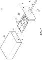
- FIG. 7 is an exploded view of the storage device according to the second embodiment of the present disclosure.
- FIG. 8 is a perspective view of a storage device with a heat dissipation function according to a third embodiment of the present disclosure.
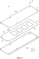
- FIG. 9 is an exploded view of the storage device according to the third embodiment of the present disclosure.
- FIG. 10 is a perspective view of a storage device with a heat dissipation function according to a fourth embodiment of the present disclosure.
- FIG. 11 is an exploded view of the storage device according to the fourth embodiment of the present disclosure.
- FIG. 12 is a perspective view of a storage device with a heat dissipation function according to a fifth embodiment of the present disclosure.
- FIG. 13 is an exploded view of the storage device according to the fifth embodiment of the present disclosure.
- FIG. 14 is an exploded view of the storage device according to the fifth embodiment of the present disclosure.
- Numbering terms such as “first”, “second” or “third” can be used to describe various components, signals or the like, which are for distinguishing one component/signal from another one only, and are not intended to, nor should be construed to impose any substantive limitations on the components, signals or the like.
- FIG. 1 and FIG. 2 are respectively a perspective view and an exploded view of a storage device with a heat dissipation function according to a first embodiment of the present disclosure
- FIG. 3 is a cross-sectional view of the storage device according to the first embodiment of the present disclosure.
- the first embodiment of the present disclosure provides a storage device U with a heat dissipation function.
- the storage device U includes a case 1 , a storage module 2 and a working fluid 3 .
- the storage device U provided by the embodiment of the present disclosure can be a hard drive; more preferably, the storage device U can be a portable external hard drive.
- the storage device U can be an internal hard drive, and the present disclosure is not limited thereto. Also, it should be noted that the storage device U with the heat dissipation function can be a hard drive U with a heat dissipation function.
- the case 1 includes an accommodation space 10
- the storage module 2 is disposed in the accommodation space 10 of the case 1 .
- the working fluid 3 is disposed in the accommodation space 10 of the case 1 so that heat generated by the storage module 2 is conducted to the case 1 through the working fluid 3 so as to improve the efficiency of heat dissipation.
- a circuit board 22 of the storage module 2 contacts the working fluid 3 directly.
- the working fluid 3 is packaged (or closed or sealed) in the accommodation space 10 of the case 1 , and the working fluid 3 is not in contact with the external environment.
- the working fluid 3 is sealed in the accommodation space 10 of the case 1 of the storage device (hard drive) U.
- at least one portion of the storage module 2 can be disposed in the accommodation space 10 of the case 1 . In this way, it is possible to only dispose the elements having a higher temperature in the accommodation space 10 and the working fluid 3 .
- the present disclosure is not limited to whether the overall structure of the storage module 2 is completely immersed in the working fluid 3 .
- a body portion 11 and a cover portion 12 of the case 1 may be made of metal, non-metal or plastic, and the present disclosure is not limited thereto.
- the storage module 2 can be a hard drive (solid state drive, SSD) interface specification, for example.
- the storage module 2 can be a hard disk drive (HDD) interface (not shown in the drawings), and the present disclosure is not limited thereto. It should be stated that the storage module 2 in the drawings of the present disclosure is illustrated as a solid hard drive interface specification.
- the storage module 2 includes a transmit port 21 and a circuit board 22 .
- the circuit board 22 is coupled to the transmit port 21 and the circuit board 22 is disposed with a plurality of chips 221 .
- the transmit port 21 is a connector that conforms SATA, mSATA, PCI-E, NVMe, M.2, M.3, ZIF, IDE, U.2, CF, CFast or type-C interface specification, for example.
- the storage device U with the heat dissipation function provided by the embodiment of the present disclosure may be a 2.5-inch hard drive, a 3.5-inch hard drive, an internal hard drive or a portable external hard drive.
- FIG. 4 and FIG. 5 are schematic views of the storage device in use according to the first embodiment of the present disclosure.
- the case 1 includes a slot body 120 , and the transmit port 21 of the storage module 2 is disposed in the slot body 120 .
- the transmit port 21 of the storage module 2 is exposed outside the accommodation space 10 of the case 1 through the slot body 120 of the case 1 . Accordingly, a transmission end 41 of a transmission line 4 passes through the slot body 120 and is connected to the transmit port 21 of the storage module 2 .
- the transmit port 21 and the transmission end 41 of the transmission line 4 in the drawings are exemplified as the type-C interface specification, but in other embodiments, the transmit port 21 and the transmission end 41 may be a connector of other interface specifications, which is not limited in the present disclosure.
- the case 1 includes the body portion 11 and the cover portion 12 disposed on the body portion 11 , and the accommodation space 10 is formed between the body portion 11 and the cover portion 12 to accommodate the circuit board 22 of the storage module 2 and the working fluid 3 .
- the body portion 11 includes a bottom plate 111 and a case plate 112 connected with the bottom plate 111 and surrounding the bottom plate 111 .
- the case plate 112 extends toward the cover portion 12 relative to the bottom plate 111 .
- the bottom plate 111 and the case plate 112 of the body portion 11 may be an integrally formed structure.
- the body portion 11 forms a cup structure for accommodating the working fluid 3 , which prevents the working fluid 3 from leaking out.
- the storage module 2 is disposed on the cover portion 12 and the cover portion 12 is disposed on the case plate 112 .
- the storage module 2 is locked on the cover portion 12 by a lock fastener (not shown in the drawings) or is fixed on the cover portion 12 by a buckle member (not shown in the drawings). Therefore, the cover portion 12 disposed with the storage module 2 can be directly combined with the body portion 11 having the working fluid 3 so as to form the storage device U with the heat dissipation function.
- the present disclosure is not limited to the form in which the storage module 2 is disposed in the case 1 .
- the manner of combining the cover portion 12 and the body portion 11 can be implemented by a lock fastener (not shown in the drawings).
- the cover portion 12 may be combined with the body portion 11 by buckling (not shown in the drawings) the cover portion 12 and the body portion 11 together.
- the cover portion 12 and the body portion 11 can be combined by gluing (such as using glue or a tape, not shown in the drawings) together.
- the present disclosure is not limited to the manner of combining the cover portion 12 with the body portion 11 as long as the cover portion 12 is combined with the body portion to prevent the working fluid 3 from leaking out.
- a rubber gasket (not shown in the drawings) may be further disposed between the cover portion 12 and the body portion 11 to improve the adhesion between the cover portion 12 and the body portion 11 , thereby preventing the working fluid 3 from leaking out.
- the case plate 112 of the body portion 11 may have a guide track (not shown in the drawings) corresponding to the storage module 2 , so that the storage module 2 can slide along the guide track to facilitate the combination of the cover portion 12 disposed with the storage module 2 and the case plate 112 of the body portion 11 disposed with the working fluid 3 .
- the cover portion 12 may further include a first cover plate 121 and a second cover plate 112 .
- the first cover plate 121 includes an opening slot 1210
- the second cover plate 122 is disposed in the opening slot 1210
- the second cover plate 112 has the slot body 120 .
- the first cover plate 121 and the second cover plate 122 may be integrally formed, and the present disclosure is not limited thereto.
- the working fluid 3 may be an insulating liquid or a dielectric liquid having an effect of heat conduction, for example, a liquid having the boiling point lower than 76° C.; preferably, a liquid having the boiling point lower 65 ; more specifically, a liquid having hydrofluoroether. That is, the present disclosure may use a pure compound or an azeotropic mixture, such as an electron fluorinated liquid and a fluorine solution, having the boiling point of 62° C., 55° C. or 48° C., to serve as the working fluid 3 , but is not limited thereto.
- a pure compound or an azeotropic mixture such as an electron fluorinated liquid and a fluorine solution
- the working fluid 3 can be the 3MTM NovecTM Engineered Fluid and the model number can be 7100 Engineered Fluid, 7200 Engineered Fluid, 7300 Engineered Fluid or 7500 Engineered Fluid, and the present disclosure is not limited thereto. Further, the working fluid 3 may be the 3MTM FluorinertTM Electronic Liquid, and the present disclosure is not limited thereto.
- the heat generated by the storage module 2 during operation is first transmitted to the working fluid 3 and then transmitted to the case 1 .
- the working fluid 3 is a liquid having the low boiling point
- the working fluid 3 is easily boiled by being heated. Consequently, the working fluid 3 rises in temperature and reaches the boiling point.
- the working fluid 3 can change phases from a liquid state to a gaseous state by using the received thermal energy. A large amount of heat is consumed during the phase change, which is helpful to improve the efficiency of heat dissipation of the storage module 2 .
- the working fluid 3 generates convection in the accommodation space 10 , and also the working fluid 3 that changes from the liquid state to the gaseous state forms air bubbles to disturb the working fluid 3 , resulting in boiling.
- the working liquid 3 may have a volume of 40% to 100% of the accommodation space 10 disposed with the storage module 2 , for example.
- the present disclosure is not limited thereto. It is worth mentioning that in one embodiment, when the material of the case 1 is a colorless translucent body made of polycarbonate (PC) resin, a user can directly observe the boiling of the working liquid 3 with the naked eye and can easily know the condition of the heat dissipation.
- PC polycarbonate
- FIG. 6 is a perspective view of a storage device with a heat dissipation function according to a second embodiment of the present disclosure
- FIG. 7 is an exploded view of the storage device according to the second embodiment of the present disclosure.
- the storage device U with the heat dissipation function provided by the second embodiment may further include the transmission line 4 , and the transmission line 4 is disposed on the cover portion 12 .
- the structures of the case 1 , the storage module 2 and the working fluid 3 are similar to those in the abovementioned embodiment, and should be omitted therein.
- the transmission end 41 of the transmission line 4 passes through the slot body 120 and is connected to the transmit port 21 of the storage module 2 as mentioned in the above embodiment.
- a package 5 covers the transmission end 41 and the slot body 120 so that the transmission line 4 is disposed on the cover portion 12 .
- the package 5 may further provide an effect of sealing between the transmission end 41 and the slot body 120 .
- the storage module 2 as mentioned in the above embodiment, is disposed on the cover portion 12 , but the present disclosure is not limited thereto.
- the package 5 and the cover portion 12 may be of the same material and integrally formed, such that the transmission end 41 of the transmission line 4 is disposed on the cover portion 12 and the transmission end 41 of the transmission line 4 is connected with the transmit port 21 of the storage module 2 disposed on the cover portion 12 .
- the package 5 and the cover portion 12 may be the same element.
- the package 5 may be merely disposed on the transmission end 41 and the slot body 120 without covering the overall cover portion 12 , and the present disclosure is not limited thereto.
- the cover portion 12 may be combined with the body portion 11 by buckling the cover portion 12 and the body portion 11 together, or by gluing together.
- the cover portion 12 and the body portion 11 can be combined in a manner that can prevent the leakage of the working fluid 3 (not shown in FIG. 6 and FIG. 7 ) and the present disclosure does not limit the manner of combining the cover portion 12 with the body portion 11 .
- FIG. 8 is a perspective view of a storage device with a heat dissipation function according to a third embodiment of the present disclosure
- FIG. 9 is an exploded view of the storage device according to the third embodiment of the present disclosure.
- the transmit port 21 of the storage module 2 of the storage device U with the heat dissipation function provided by the third embodiment can be PCI-E interface specification.
- the arrangement of the case 1 in the third embodiment is different from the above embodiments.
- the storage module 2 and the working fluid 3 of the storage device U with the heat dissipation function provided by the third embodiment are similar to those in the above embodiments, and should be omitted herein.
- the case 1 may be composed of the body portion 11 and the cover portion 12 .
- the body portion 11 of the third embodiment may be composed of a first case plate 113 and a second case plate 114 , and a lock fastener 6 may be used between the first case plate 113 and the second case plate 114 to combine the first case plate 113 with the second case plate 114 , but the present disclosure is not limited thereto.
- a rubber gasket (not shown in the drawings) may be further disposed between the first case plate 113 and the second case plate 114 to improve the adhesion between the first case plate 113 and the second case plate 114 .
- the cover portion 12 may be a colloid used to close a gap formed between the first case plate 113 and the second case plate 114 , but the present disclosure is not limited thereto.
- the gap formed between the first case plate 113 and the second case plate 114 may be closed by ultrasonic welding to further form the cover portion 12 .
- FIG. 10 is a perspective view of a storage device with a heat dissipation function according to a fourth embodiment of the present disclosure
- FIG. 11 is an exploded view of the storage device according to the fourth embodiment of the present disclosure.
- the storage device U with the heat dissipation function provided by the fourth embodiment can provide merely a portion of the storage module 2 in the accommodation space 10 in the case 1 . That is, it is possible to merely dispose the elements having a higher temperature in the accommodation space 10 of the case 1 and in the working fluid 3 .
- the storage module 2 and the working fluid 3 of the storage device U with the heat dissipation function provided by the fourth embodiment are still similar to those in the above embodiments, and should be omitted therein.
- the body portion 11 of the case 1 of the fourth embodiment can be composed of the bottom plate 111 and the case plate 112 .
- the cover portion 12 of the case 1 of the fourth embodiment can be a colloid as mentioned in the third embodiment to close the gap formed between the storage module 2 and the case plate 112 of the body portion 11 , but the present disclosure is not limited thereto.
- the gap formed between the storage module 2 and the case plate 112 of the body portion 11 can be closed by ultrasonic welding to further form the cover portion 12 .
- FIG. 12 is a perspective view of a storage device with a heat dissipation function according to a fifth embodiment of the present disclosure
- FIG. 13 and FIG. 14 are exploded views of the storage device according to the fifth embodiment of the present disclosure.
- the case 1 accommodating the working fluid 3 can cover one of the chips 221 which is easier heated, so that the chip 221 which is easier heated is immersed in the working fluid 3 . Accordingly, the heat generated by the chip 221 of the storage module 3 can be conducted from the working fluid 3 to the case 1 .
- One of the beneficial effects of the present disclosure is that, with the technical solution that “the working fluid 3 is disposed in the accommodation space 10 of the case 1 , and the storage module 2 is immersed in the working fluid 3 ,” the storage device U and the hard drive U with the heat dissipation function provided by the embodiment of the present disclosure improve the efficiency of heat dissipation of the storage device U and the hard drive U. Therefore, the heat generated by the storage module 2 can be quickly transmitted from the working fluid 3 to the case 1 through the working fluid 3 , so as to prevent the storage device U and the hard drive U from overheating and a decrease in the transmission speed.
Landscapes
- Engineering & Computer Science (AREA)
- Microelectronics & Electronic Packaging (AREA)
- Physics & Mathematics (AREA)
- Thermal Sciences (AREA)
- Cooling Or The Like Of Electrical Apparatus (AREA)
Abstract
Description
Claims (15)
Applications Claiming Priority (3)
| Application Number | Priority Date | Filing Date | Title |
|---|---|---|---|
| TW107129310A | 2018-08-22 | ||
| TW107129310A TWI669479B (en) | 2018-08-22 | 2018-08-22 | Storage device and hard disk with heat dissipation function |
| TW107129310 | 2018-08-22 |
Publications (2)
| Publication Number | Publication Date |
|---|---|
| US20200068743A1 US20200068743A1 (en) | 2020-02-27 |
| US10694639B2 true US10694639B2 (en) | 2020-06-23 |
Family
ID=68316719
Family Applications (1)
| Application Number | Title | Priority Date | Filing Date |
|---|---|---|---|
| US16/183,687 Active US10694639B2 (en) | 2018-08-22 | 2018-11-07 | Storage device and hard drive with heat dissipation function |
Country Status (3)
| Country | Link |
|---|---|
| US (1) | US10694639B2 (en) |
| CN (1) | CN110858494A (en) |
| TW (1) | TWI669479B (en) |
Families Citing this family (2)
| Publication number | Priority date | Publication date | Assignee | Title |
|---|---|---|---|---|
| USD903665S1 (en) * | 2018-02-01 | 2020-12-01 | Hewlett-Packard Development Company, L.P. | Computer |
| USD920330S1 (en) * | 2018-04-18 | 2021-05-25 | Seagate Technology Llc | Storage device |
Citations (9)
| Publication number | Priority date | Publication date | Assignee | Title |
|---|---|---|---|---|
| US3741292A (en) | 1971-06-30 | 1973-06-26 | Ibm | Liquid encapsulated air cooled module |
| US6992888B1 (en) | 2004-03-08 | 2006-01-31 | Lockheed Martin Corporation | Parallel cooling of heat source mounted on a heat sink by means of liquid coolant |
| US20060152899A1 (en) * | 2005-01-07 | 2006-07-13 | Datastor Technology Co., Ltd. | External data storage device with decorative illuminating effect |
| US7414838B2 (en) * | 2005-06-02 | 2008-08-19 | Hotway Technology Corp. | Heating dissipating structure of an external hard disk drive box |
| US20100296236A1 (en) * | 2009-05-21 | 2010-11-25 | Ocz Technology Group, Inc. | Mass storage device for a computer system and method therefor |
| TW201419673A (en) | 2012-09-11 | 2014-05-16 | Apple Inc | Connector bracket |
| CN104321939A (en) | 2012-03-12 | 2015-01-28 | 哈梅尔公司 | Portable device comprising an electrical cable |
| TWM513441U (en) | 2015-05-13 | 2015-12-01 | Silicon Power Comp & Comm Inc | Portable storage device with waterproof function |
| US9872415B2 (en) * | 2015-12-01 | 2018-01-16 | Dell Products, L.P. | Dry power supply assembly for immersion-cooled information handling systems |
Family Cites Families (7)
| Publication number | Priority date | Publication date | Assignee | Title |
|---|---|---|---|---|
| US20060090881A1 (en) * | 2004-10-29 | 2006-05-04 | 3M Innovative Properties Company | Immersion cooling apparatus |
| CN201051400Y (en) * | 2007-04-03 | 2008-04-23 | 深圳易拓科技有限公司 | Mobile hard disk box |
| CN201374188Y (en) * | 2008-12-12 | 2009-12-30 | 富港电子(东莞)有限公司 | Hard disk external box |
| FR3016266B1 (en) * | 2014-01-07 | 2018-03-16 | Safran Electronics & Defense | ELECTRONIC POWER DEVICE WITH IMPROVED COOLING |
| EP3197945B1 (en) * | 2014-09-23 | 2020-10-21 | 3M Innovative Properties Company | Nitrogen containing hydrofluoroethers and methods of using same |
| CN110475459B (en) * | 2014-09-26 | 2021-07-13 | 液体冷却解决方案公司 | Cooling method for heat-generating electronic components and electronic system for liquid immersion cooling |
| CN206323733U (en) * | 2017-01-10 | 2017-07-11 | 广东合一新材料研究院有限公司 | A kind of working fluid submerges cooled power amplifier in transmitter unit entirely |
-
2018
- 2018-08-22 TW TW107129310A patent/TWI669479B/en active
- 2018-08-31 CN CN201811013018.XA patent/CN110858494A/en active Pending
- 2018-11-07 US US16/183,687 patent/US10694639B2/en active Active
Patent Citations (9)
| Publication number | Priority date | Publication date | Assignee | Title |
|---|---|---|---|---|
| US3741292A (en) | 1971-06-30 | 1973-06-26 | Ibm | Liquid encapsulated air cooled module |
| US6992888B1 (en) | 2004-03-08 | 2006-01-31 | Lockheed Martin Corporation | Parallel cooling of heat source mounted on a heat sink by means of liquid coolant |
| US20060152899A1 (en) * | 2005-01-07 | 2006-07-13 | Datastor Technology Co., Ltd. | External data storage device with decorative illuminating effect |
| US7414838B2 (en) * | 2005-06-02 | 2008-08-19 | Hotway Technology Corp. | Heating dissipating structure of an external hard disk drive box |
| US20100296236A1 (en) * | 2009-05-21 | 2010-11-25 | Ocz Technology Group, Inc. | Mass storage device for a computer system and method therefor |
| CN104321939A (en) | 2012-03-12 | 2015-01-28 | 哈梅尔公司 | Portable device comprising an electrical cable |
| TW201419673A (en) | 2012-09-11 | 2014-05-16 | Apple Inc | Connector bracket |
| TWM513441U (en) | 2015-05-13 | 2015-12-01 | Silicon Power Comp & Comm Inc | Portable storage device with waterproof function |
| US9872415B2 (en) * | 2015-12-01 | 2018-01-16 | Dell Products, L.P. | Dry power supply assembly for immersion-cooled information handling systems |
Also Published As
| Publication number | Publication date |
|---|---|
| TW202009441A (en) | 2020-03-01 |
| CN110858494A (en) | 2020-03-03 |
| US20200068743A1 (en) | 2020-02-27 |
| TWI669479B (en) | 2019-08-21 |
Similar Documents
| Publication | Publication Date | Title |
|---|---|---|
| US8439632B2 (en) | Thermal module with airflow guiding function | |
| US7554805B2 (en) | Heat dissipation structure for electronic devices | |
| US20140146461A1 (en) | Secondary Memory Device | |
| US20040188069A1 (en) | Electronic apparatus having a circulating path of liquid coolant | |
| JP7282509B2 (en) | SOLID STATE DRIVE DEVICE AND DATA STORAGE SYSTEM HAVING THE SAME | |
| US20210378145A1 (en) | Electronic device | |
| US11099616B2 (en) | Heat dissipating housing and pluggable electronic device having the same | |
| US10694639B2 (en) | Storage device and hard drive with heat dissipation function | |
| US10437299B2 (en) | Heat-dissipating structure of electronic device | |
| US20200107469A1 (en) | Wireless charging device with heat dissipation function | |
| AU2023200811B2 (en) | Waterproof electronic device and fan device thereof | |
| US20060171114A1 (en) | Heat dissipation device for computer hard drive | |
| KR20060018202A (en) | Electronics | |
| CN209708058U (en) | Modular chassis | |
| US20110304992A1 (en) | Heat dissipation device | |
| US8295045B2 (en) | Case and electronic device having the same | |
| CN209527034U (en) | A waterproof, shock-absorbing and heat-dissipating structure for vehicle-mounted electronic products | |
| CN108633213A (en) | Electronic device | |
| CN211980204U (en) | solid state drive | |
| KR102954176B1 (en) | Semiconductor device | |
| TW202603316A (en) | Two-phase fluid heat dissipation module and a product thereof | |
| KR101493943B1 (en) | Heat dissipation system for a server | |
| JP7855097B1 (en) | Electronic equipment and fans | |
| CN201017653Y (en) | Shockproof HDD | |
| CN218416544U (en) | Gunlock camera structure with heat dissipation and waterproof performance |
Legal Events
| Date | Code | Title | Description |
|---|---|---|---|
| AS | Assignment |
Owner name: ADATA TECHNOLOGY CO., LTD., TAIWAN Free format text: ASSIGNMENT OF ASSIGNORS INTEREST;ASSIGNORS:KUO, TSUNG-HSING;PAN, JEN-CHIEH;REEL/FRAME:048100/0737 Effective date: 20181008 |
|
| FEPP | Fee payment procedure |
Free format text: ENTITY STATUS SET TO UNDISCOUNTED (ORIGINAL EVENT CODE: BIG.); ENTITY STATUS OF PATENT OWNER: LARGE ENTITY |
|
| AS | Assignment |
Owner name: ADATA TECHNOLOGY CO., LTD., TAIWAN Free format text: ASSIGNMENT OF ASSIGNORS INTEREST;ASSIGNORS:KUO, TSUNG-HSING;PAN, JEN-CHIEH;REEL/FRAME:048000/0801 Effective date: 20181008 |
|
| STPP | Information on status: patent application and granting procedure in general |
Free format text: RESPONSE TO NON-FINAL OFFICE ACTION ENTERED AND FORWARDED TO EXAMINER |
|
| STPP | Information on status: patent application and granting procedure in general |
Free format text: AWAITING TC RESP., ISSUE FEE NOT PAID |
|
| STCF | Information on status: patent grant |
Free format text: PATENTED CASE |
|
| MAFP | Maintenance fee payment |
Free format text: PAYMENT OF MAINTENANCE FEE, 4TH YEAR, LARGE ENTITY (ORIGINAL EVENT CODE: M1551); ENTITY STATUS OF PATENT OWNER: LARGE ENTITY Year of fee payment: 4 |