US10694405B2 - Apparatus and method for setting a local oscillator duty ratio based on an image distortion level - Google Patents
Apparatus and method for setting a local oscillator duty ratio based on an image distortion level Download PDFInfo
- Publication number
- US10694405B2 US10694405B2 US15/343,095 US201615343095A US10694405B2 US 10694405 B2 US10694405 B2 US 10694405B2 US 201615343095 A US201615343095 A US 201615343095A US 10694405 B2 US10694405 B2 US 10694405B2
- Authority
- US
- United States
- Prior art keywords
- signal
- transmitter
- phase path
- duty ratio
- distortion level
- Prior art date
- Legal status (The legal status is an assumption and is not a legal conclusion. Google has not performed a legal analysis and makes no representation as to the accuracy of the status listed.)
- Active, expires
Links
- 238000000034 method Methods 0.000 title claims abstract description 42
- 230000005540 biological transmission Effects 0.000 claims abstract description 25
- 238000005259 measurement Methods 0.000 claims abstract description 21
- 238000004891 communication Methods 0.000 claims description 11
- 238000012937 correction Methods 0.000 description 15
- 230000006735 deficit Effects 0.000 description 10
- 238000013461 design Methods 0.000 description 6
- 230000006870 function Effects 0.000 description 4
- 230000006872 improvement Effects 0.000 description 4
- 101100298835 Saccharomyces cerevisiae (strain ATCC 204508 / S288c) RPT1 gene Proteins 0.000 description 3
- 238000004590 computer program Methods 0.000 description 3
- 238000013519 translation Methods 0.000 description 3
- 238000001914 filtration Methods 0.000 description 2
- 230000003287 optical effect Effects 0.000 description 2
- 238000012545 processing Methods 0.000 description 2
- 230000009467 reduction Effects 0.000 description 2
- 230000003252 repetitive effect Effects 0.000 description 2
- 230000003213 activating effect Effects 0.000 description 1
- 230000006399 behavior Effects 0.000 description 1
- 230000001413 cellular effect Effects 0.000 description 1
- 238000010586 diagram Methods 0.000 description 1
- 230000007717 exclusion Effects 0.000 description 1
- 238000003702 image correction Methods 0.000 description 1
- 230000007246 mechanism Effects 0.000 description 1
- 238000012986 modification Methods 0.000 description 1
- 230000004048 modification Effects 0.000 description 1
- 230000004044 response Effects 0.000 description 1
- 230000000630 rising effect Effects 0.000 description 1
- 239000007787 solid Substances 0.000 description 1
Images


Classifications
-
- H—ELECTRICITY
- H04—ELECTRIC COMMUNICATION TECHNIQUE
- H04W—WIRELESS COMMUNICATION NETWORKS
- H04W24/00—Supervisory, monitoring or testing arrangements
- H04W24/08—Testing, supervising or monitoring using real traffic
-
- H—ELECTRICITY
- H03—ELECTRONIC CIRCUITRY
- H03D—DEMODULATION OR TRANSFERENCE OF MODULATION FROM ONE CARRIER TO ANOTHER
- H03D3/00—Demodulation of angle-, frequency- or phase- modulated oscillations
- H03D3/001—Details of arrangements applicable to more than one type of frequency demodulator
- H03D3/003—Arrangements for reducing frequency deviation, e.g. by negative frequency feedback
- H03D3/004—Arrangements for reducing frequency deviation, e.g. by negative frequency feedback wherein the demodulated signal is used for controlling an oscillator, e.g. the local oscillator
-
- H—ELECTRICITY
- H03—ELECTRONIC CIRCUITRY
- H03F—AMPLIFIERS
- H03F1/00—Details of amplifiers with only discharge tubes, only semiconductor devices or only unspecified devices as amplifying elements
- H03F1/32—Modifications of amplifiers to reduce non-linear distortion
- H03F1/3241—Modifications of amplifiers to reduce non-linear distortion using predistortion circuits
- H03F1/3247—Modifications of amplifiers to reduce non-linear distortion using predistortion circuits using feedback acting on predistortion circuits
-
- H—ELECTRICITY
- H03—ELECTRONIC CIRCUITRY
- H03F—AMPLIFIERS
- H03F3/00—Amplifiers with only discharge tubes or only semiconductor devices as amplifying elements
- H03F3/20—Power amplifiers, e.g. Class B amplifiers, Class C amplifiers
- H03F3/24—Power amplifiers, e.g. Class B amplifiers, Class C amplifiers of transmitter output stages
-
- H—ELECTRICITY
- H04—ELECTRIC COMMUNICATION TECHNIQUE
- H04L—TRANSMISSION OF DIGITAL INFORMATION, e.g. TELEGRAPHIC COMMUNICATION
- H04L5/00—Arrangements affording multiple use of the transmission path
- H04L5/003—Arrangements for allocating sub-channels of the transmission path
- H04L5/0048—Allocation of pilot signals, i.e. of signals known to the receiver
-
- H—ELECTRICITY
- H04—ELECTRIC COMMUNICATION TECHNIQUE
- H04W—WIRELESS COMMUNICATION NETWORKS
- H04W72/00—Local resource management
- H04W72/04—Wireless resource allocation
- H04W72/044—Wireless resource allocation based on the type of the allocated resource
-
- H—ELECTRICITY
- H03—ELECTRONIC CIRCUITRY
- H03D—DEMODULATION OR TRANSFERENCE OF MODULATION FROM ONE CARRIER TO ANOTHER
- H03D2200/00—Indexing scheme relating to details of demodulation or transference of modulation from one carrier to another covered by H03D
- H03D2200/0041—Functional aspects of demodulators
- H03D2200/0045—Calibration of demodulators
-
- H—ELECTRICITY
- H03—ELECTRONIC CIRCUITRY
- H03D—DEMODULATION OR TRANSFERENCE OF MODULATION FROM ONE CARRIER TO ANOTHER
- H03D2200/00—Indexing scheme relating to details of demodulation or transference of modulation from one carrier to another covered by H03D
- H03D2200/0041—Functional aspects of demodulators
- H03D2200/0088—Reduction of intermodulation, nonlinearities, adjacent channel interference; intercept points of harmonics or intermodulation products
-
- H—ELECTRICITY
- H04—ELECTRIC COMMUNICATION TECHNIQUE
- H04B—TRANSMISSION
- H04B1/00—Details of transmission systems, not covered by a single one of groups H04B3/00 - H04B13/00; Details of transmission systems not characterised by the medium used for transmission
- H04B1/02—Transmitters
- H04B1/04—Circuits
- H04B1/0475—Circuits with means for limiting noise, interference or distortion
-
- H—ELECTRICITY
- H04—ELECTRIC COMMUNICATION TECHNIQUE
- H04B—TRANSMISSION
- H04B1/00—Details of transmission systems, not covered by a single one of groups H04B3/00 - H04B13/00; Details of transmission systems not characterised by the medium used for transmission
- H04B1/02—Transmitters
- H04B1/04—Circuits
- H04B2001/0408—Circuits with power amplifiers
-
- H—ELECTRICITY
- H04—ELECTRIC COMMUNICATION TECHNIQUE
- H04L—TRANSMISSION OF DIGITAL INFORMATION, e.g. TELEGRAPHIC COMMUNICATION
- H04L27/00—Modulated-carrier systems
- H04L27/0014—Carrier regulation
- H04L2027/0016—Stabilisation of local oscillators
-
- H—ELECTRICITY
- H04—ELECTRIC COMMUNICATION TECHNIQUE
- H04L—TRANSMISSION OF DIGITAL INFORMATION, e.g. TELEGRAPHIC COMMUNICATION
- H04L27/00—Modulated-carrier systems
- H04L27/0014—Carrier regulation
- H04L2027/0018—Arrangements at the transmitter end
Definitions
- the present invention relates to communication systems, and more particularly to transmitter calibration techniques.
- the distortion measurements are typically performed using an on-chip measurement receiver, and some calibration techniques [e.g. third-order CIM (CIM3) calibration, etc.] may require measurement of very low levels of distortions, which may be difficult.
- CIM3 calibration third-order CIM
- An apparatus and method are provided for setting a local oscillator duty ratio based on an image distortion level.
- a first signal is transmitted utilizing a first X-phase path of a transmitter. Further, an image distortion level is measured in connection with the first signal. Based on the measurement, a duty ratio of a local oscillator is set, for reducing a distortion in connection with a transmission of a second signal utilizing a second Y-phase path of the transmitter.
- the first signal may include a calibration signal. Further, the second Y-phase path of the transmitter may be disabled during the transmission of the first signal.
- the first X-phase path of the transmitter may include a 4-phase path
- the second Y-phase path of the transmitter may include an 8-phase path
- the distortion that is reduced in connection with the transmission of the second signal utilizing the second Y-phase path of the transmitter may include image distortion.
- the distortion that is reduced in connection with the transmission of the second signal utilizing the second Y-phase path of the transmitter may include a type of distortion other than an image distortion [e.g. counter-intermodulation (CIM) distortion, harmonic distortion, etc.].
- CIM counter-intermodulation
- the transmitting, measuring, and setting may be part of a single calibration of the transmitter that is required prior to being shipped by a manufacturer of the transmitter. Further, a calibration utilizing the second Y-phase path of the transmitter may be avoided by such transmitting, measuring, and setting.
- the first signal may be calibrated, based on a measurement of an output of at least one low pass filter of the transmitter.
- one or more of the foregoing features of the aforementioned apparatus and method may provide a simpler calibration technique that is capable of correcting multiple impairments using a single calibration measurement. Further, such single calibration measurement may rely on an easier-to-measure image distortion. This may result in reduced circuit complexity and less time which, in turn, may potentially provide a cost savings that would otherwise be foregone in systems that lack such simpler calibration technique. It should be noted that the aforementioned potential advantages are set forth for illustrative purposes only and should not be construed as limiting in any manner.
- FIG. 1 illustrates a method for setting a local oscillator duty ratio based on an image distortion level, in accordance with one embodiment.
- FIG. 2 illustrates a system for setting a local oscillator duty ratio based on an image distortion level, in accordance with one embodiment.
- FIG. 3A illustrates a sample plot of an output of a local oscillator, in accordance with one embodiment.
- FIG. 3B is a plot of an image distortion level versus harmonics or CIM distortion, in accordance with one embodiment.
- FIG. 4 illustrates a plot showing a relationship between a clock duty ratio (as defined by clock pulses over time), and a threshold voltage of a local oscillator.
- FIG. 5A illustrates a system for setting a local oscillator duty ratio based on an image distortion level, in accordance with another embodiment.
- FIG. 5B illustrates a system for adjusting a calibration signal, in accordance with yet another embodiment.
- FIG. 6 illustrates a method for setting a local oscillator duty ratio based on an image distortion level, in accordance with one embodiment.
- FIG. 7A illustrates a plot showing 4-phase mode image distortion with and without clock duty ratio calibration.
- FIG. 7B illustrates a plot showing 8-phase mode CIM distortion with and without clock duty ratio calibration.
- FIG. 7C illustrates a plot showing 8-phase mode harmonics distortion with and without clock duty ratio calibration.
- FIG. 8 illustrates a network architecture, in accordance with one possible embodiment.
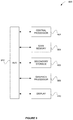
- FIG. 9 illustrates an exemplary system, in accordance with one embodiment.
- FIG. 1 illustrates a method 100 for setting a local oscillator duty ratio based on an image distortion level, in accordance with one embodiment.
- a first signal is transmitted utilizing a first X-phase path of a transmitter.
- the first signal may include any signal capable of being transmitted via the transmitter.
- the first signal may include a calibration signal.
- the transmitter may include any circuitry configured for causing transmission of radio frequency (RF) signals.
- the first X-phase path of the transmitter may include any circuit, componentry and/or conductive element that is capable of carrying, storing, and/or processing the first signal in a form where the first signal has multiple (e.g. any integer X) phases.
- an image distortion level is measured in connection with the first signal, per operation 104 .
- image distortion level may refer to any amplitude of image distortion exhibited by the first signal.
- image distortion may refer to an upper-sideband signal that is exhibited at a lower-sideband (and vice versa). More information regarding exemplary image distortion will be set forth in greater detail during reference to subsequent embodiments/figures.
- a duty ratio of a local oscillator is set in operation 106 , for reducing a distortion in connection with a transmission of a second signal utilizing a second Y-phase path of the transmitter.
- the local oscillator may include any oscillating circuit or element that produces a repetitive signal that controls at least one aspect or component (e.g. a mixer, etc.) of the first X-phase path and/or the second Y-phase path of the transmitter.
- the second signal may include any signal (e.g. data transmission signal, etc.) capable of being transmitted via the transmitter, while the second Y-phase path of the transmitter may include any circuit, componentry and/or conductive element that is capable of carrying, storing, and/or processing the second signal in a form where the second signal has multiple (e.g. any integer Y ⁇ X) phases.
- the first X-phase path of the transmitter may include a 4-phase path
- the second Y-phase path of the transmitter may include an 8-phase path.
- the first X-phase path and the second Y-phase path have any different number of phases (e.g. 4/16, 4/12 etc.).
- the local oscillator duty ratio is set as a function of the first signal measurement (in connection with the first X-phase path), for reducing a distortion in connection with a transmission of the second signal utilizing the second Y-phase path of the transmitter.
- such distortion may or may not include the image distortion.
- a type of the distortion may include a type other than the image distortion [e.g. counter-intermodulation (CIM) distortion, harmonic distortion, etc.]. More information regarding such other types of distortion will be set forth in greater detail during reference to subsequent embodiments/figures.
- the first signal may be transmitted as a calibration signal in connection with a single calibration of the transmitter (that is required prior to being shipped), and the second Y-phase path of the transmitter may be disabled during the transmission of the first signal.
- the first signal may be the sole basis for adjusting the local oscillator duty ratio for affording distortion reduction during use of the second Y-phase path (after being shipped/calibrated).
- a calibration utilizing the second Y-phase path of the transmitter may, in one embodiment, be avoided using the method 100 of FIG. 1 .
- one or more of the foregoing features may provide a simpler calibration technique that is capable of correcting multiple impairments using a single calibration measurement. Further, such single calibration measurement may rely on an easier-to-measure image distortion. This may result in reduced circuit complexity and less time which, in turn, may potentially provide a cost savings that would otherwise be foregone in systems that lack such simpler calibration technique. It should be noted that the aforementioned potential advantages are set forth for illustrative purposes only and should not be construed as limiting in any manner.
- the first signal may, in one optional embodiment, be calibrated, based on a measurement of an output of at least one low pass filter of the transmitter, as will become apparent later. It should be noted that the following information is set forth for illustrative purposes and should not be construed as limiting in any manner. Any of the following features may be optionally incorporated with or without the exclusion of other features described.
- FIG. 2 illustrates a system 200 for setting a local oscillator duty ratio based on an image distortion level, in accordance with one embodiment.
- the system 200 may be implemented in the context of any one or more of the embodiments set forth in any previous and/or subsequent figure(s) and/or description thereof.
- the system 200 may be configured to carry out the method 100 of FIG. 1 .
- the system 200 may be implemented in the context of any desired environment.
- the system 200 includes a transceiver 202 having a transmitter 204 including: a first X-phase path 206 with at least one element/component 208 (e.g. a conductive element, mixer, etc.), and a second Y-phase path 210 with at least one element/component 212 (e.g. a conductive element, mixer, etc.).
- X X ⁇ Y such that the first X-phase path 206 utilizes fewer phases with respect to the second Y-phase path 210 .
- the transmitter 204 further includes a local oscillator 214 for driving at least one aspect (e.g.
- the local oscillator 214 may serve to drive a cycle rate of mixers to control a rate at which the first X-phase path 206 and the second Y-phase path 210 cycle through the relative phases.
- a switch 215 may be provided for switching between the first X-phase path 206 and the second Y-phase path 210 so that output is enabled only from one (while the other is optionally disabled, for power savings).
- the system 200 includes a power amplifier/front end 217 and a receiver 216 in electrical communication with an output of the transmitter 204 , for receiving signals emitted therefrom. Further provided is a control circuit 218 that is in electrical communication with the receiver 216 , and an input 219 and the local oscillator 214 of the transmitter 204 .
- the control circuit 218 serves to provide a calibration signal at the input 219 of the transmitter 204 while the switch 215 enables emission of the signal solely via the first X-phase path 206 , while being driven by the local oscillator 214 (and while the second Y-phase path 210 is optionally powered down).
- the receiver 216 is capable of receiving the signal and directing the same back to the control circuit 218 for measuring an image distortion level thereof.
- the control circuit 218 may use a correlation between such image distortion and a local oscillator duty ratio, to identify any error in the duty ratio and correct the same (via the local oscillator 214 ). More information will now be set forth on a relationship between the local oscillator duty ratio error and various distortions (e.g. image, CIM, harmonics, etc. distortion).
- FIG. 3A illustrates a sample plot 300 of an output of an local oscillator, in accordance with one embodiment.
- the sample plot 300 shows an ideal plot 302 and an actual plot 304 with an error 306 therebetween.
- the local oscillator duty ratio error is a significant impairment and dominates various transmitter performance parameters including 4-phase mode image distortion, 8-phase mode CIM distortion, 8-phase mode harmonics distortion, etc. Therefore, estimating and correcting the duty ratio error may, in one embodiment, reduce all three distortion levels.
- the local oscillator deviates 50% from an input clock, and both rising and falling edges are used to generate the output clock.
- the duty ratio error may translate to the output and create asymmetrical output signals.
- 25 and 12.5 may be an ideal duty ratio (in percent) for 4-phase and 8-phase modes of operation.
- the residual third harmonics level (after non-perfect cancellation) is proportional to Equation #1.
- the 3rd or 5th harmonics are linearly proportional to the duty ratio error, which means CIM3 and CIM5 distortions are linearly proportional to the clock duty ratio error, as well.
- all three impairments e.g. image, CIM, and harmonics
- FIG. 3B is a plot 310 of an image distortion level versus harmonics or CIM distortion, in accordance with one embodiment. As shown, the plot exhibits a slope of one (1), since all three distortions (e.g. image, CIM, and harmonics) are linearly proportional to duty ratio error.
- An offset 312 of the linear line of the plot 310 is determined by a linearity of an RF VGA, PA, and/or frequency response of the VGA, etc. However, the offset 312 is fixed for a fixed design of transmission componentry (e.g. mixer, transmitter RF VGA, PA, etc.). More information regarding examples of such componentry will be set forth later during the description of subsequent embodiments/figures. In the meantime, more information on various techniques for adjusting a clock duty ratio will now be set forth.
- FIG. 4 illustrates a plot 400 showing a relationship between a clock duty ratio (as defined by clock pulses over time), and a threshold voltage of a local oscillator.
- the clock duty ratio may be adjusted by adjusting a divider input threshold voltage. Specifically, moving such threshold level up effectively reduces a “clock on” duty, and moving the threshold level down effectively reduces a “clock off” time. In another words, the clock duty ratio may be adjusted by moving the threshold voltage up and down.
- FIG. 5A illustrates a system 500 for setting a local oscillator duty ratio based on an image distortion level, in accordance with another embodiment.
- the system 500 may be implemented in the context of any one or more of the embodiments set forth in any previous and/or subsequent figure(s) and/or description thereof.
- the system 500 may be configured to carry out the method 100 of FIG. 1 .
- the system 500 may be implemented in the context of any desired environment.
- the system 500 includes a transceiver 503 having a transmitter 504 including: a first X-phase path 506 , and a second Y-phase path 510 , where X ⁇ Y.
- the transceiver 503 further includes a local oscillator (LO) generation circuit 514 and a switch 515 .
- the system 500 includes a receiver 516 , and control circuitry 518 .
- Each of the forgoing components may operate similar to the corresponding components (e.g. 202 , 204 , 206 , 210 , 214 , 216 , and 218 , etc.) of FIG. 2 .
- the first X-phase path 506 , and the second Y-phase path 510 of the transmitter 504 include a pair of filters 520 A, 520 B for filtering an input signal, a phase interpolation circuit 522 for generating the proper input signals to the mixer, a pair of mixers 524 A, 524 B for mixing the different phases across the signal, and a pair of variable gain amplifiers 526 A, 526 B for amplifying the mixed signal, all serially interconnected in the manner shown.
- the LO generation circuit 514 includes a duty ratio correction circuit 530 that is configured for activating (e.g. see pulse signal of FIG. 4 , etc.) the mixers 524 A, 524 B at a predetermined frequency via a pair of dividers 532 , 534 interconnected in the manner shown.
- the dividers 532 , 534 divide (e.g. by two, etc.) a frequency of an output of the duty ratio correction circuit 530 such that the mixers 524 A, 524 B of the different paths 506 , 510 are driven at different frequencies. Further, the output of the duty ratio correction circuit 530 is governed by a clock signal from a phase locked loop (PLL) 536 and a code word received from the control circuitry 518 , in a manner that will soon become apparent.
- PLL phase locked loop
- the system 500 is equipped with a power amplifier 540 for amplifying an output of the transmitter 504 .
- a bandpass filter 542 e.g. duplexer, etc.
- the system 500 is equipped with a power amplifier 540 for amplifying an output of the transmitter 504 .
- a bandpass filter 542 e.g. duplexer, etc.
- a continuous wave (CW) calibration source 564 for generating I/Q channel signals.
- I/Q channel signals may be emitted by the CW calibration source 564 , as calibration signals.
- calibration signals may include single-tone/frequency signals.
- the CW calibration source 564 may be in communication with a pair of digital to analog converters 548 A, 548 B which convert the I/Q channel signals from a digital format to an analog format, before feeding the same to the low pass filters 520 A, 520 B of the transmitter 504 for being passed to the antenna 544 (and the receiver 516 ) via the first X-phase path 506 for being measured by the control circuitry 518 for calibration purposes, as will soon become apparent.
- control circuitry 518 further includes a pair of analog to digital converters 550 A, 550 B that are in communication with the receiver 516 for independently receiving both I/Q channel signals from the receiver 516 and converting such signals from an analog format to a digital format.
- an IQ amplitude and phase error estimator 552 in communication with the analog to digital converters 550 A, 550 B for receiving the digital I/Q channel signals therefrom.
- the IQ amplitude and phase error estimator 552 measures a level of image distortion in the digital I/Q channel signals and, as an option, any phase component of such image distortion (albeit smaller).
- the IQ amplitude and phase error estimator 552 may serve to estimate a path gain mismatch (e.g. error in the Q channel signal versus error in the I channel signal, etc.).
- the IQ amplitude and phase error estimator 552 feeds the same to a duty ratio error estimator 556 .
- the duty ratio error estimator 556 translates the image distortion level to a particular code word that is associated with a particular duty ratio correction amount. In one embodiment, such translation may be accomplished utilizing a look-up table such that set forth in Table 1.
- image_distortion_level_1 code_word_1 associated with a first correction amount
- image_distortion_level_2 code_word_2 associated with a second correction amount
- image_distortion_level_3 code_word_3 associated with a third correction amount
- such look-up table may be stored in memory for use with a circuit to cause a duty ratio of the local oscillator to be set based on the image distortion (via the code words, etc.). It should be noted, however, that other translation techniques (e.g. using translation digital logic, etc.) may be employed, in other embodiments.
- the code word is output from the duty ratio error estimator 556 to the duty ratio correction circuit 530 of the LO generation circuit 514 , and the duty ratio correction circuit 530 serves to raise or lower the voltage threshold to achieve the associated duty ratio correction amount.
- the specific relationship between the image distortion levels, the specific code words, the voltage thresholds/duty ratio correction amounts, etc. may all be set as a function of design-specific parameters associated with the components (e.g. 520 A, 520 B, 522 , 524 A, 524 B, 526 A, and/or 526 B, etc.) of the first X-phase path 506 (and possibly the second Y-phase path 510 ) of the transmitter 504 , so that an optimal duty ratio correction amount is prompted by the measured image distortion level.
- FIG. 5B illustrates a system 570 for adjusting a calibration signal, in accordance with yet another embodiment.
- the system 570 may be implemented in the context of any one or more of the embodiments set forth in any previous and/or subsequent figure(s) and/or description thereof.
- the system 570 may be configured to carry out the method 100 of FIG. 1 .
- the system 570 may be implemented in the context of any desired environment.
- the system 570 includes the transceiver 503 and the associated components [the description of which (in reference to FIG. 5A ) is incorporated herein by reference].
- the control circuitry 518 of the system 570 further includes a pair of analog to digital converters 560 A, 560 B that are fed by a tap at an output of the low pass filters 520 A, 520 B of the transmitter 504 , for translating signals at such tap from an analog format to a digital format.
- Such analog to digital converters 560 A, 560 B are in communication with a low pass filter (LPF)/digital to analog convert (DAC) IQ mismatch estimator 562 which, in turn, is communication with a LPF/DAC image digital pre-distortion (DPD) module 562 that sits between the CW calibration source 564 and the pair of digital to analog converters 548 A, 548 B, as shown.
- LPF low pass filter
- DAC digital to analog convert
- DPD digital pre-distortion
- the LPF/DAC IQ mismatch estimator 562 and the LPF/DAC image DPD module 562 may serve to calibrate an analog section of the first X-phase path 506 (and possibly the second Y-phase path 510 ) of the transmitter 504 including the digital to analog converters 548 A, 548 B and the low pass filters 520 A, 520 B. Specifically, such calibration may serve to remove the image distortion generated by the foregoing components, by the LPF/DAC IQ mismatch estimator 562 identifying an error at an output of the low pass filters 520 A, 520 B which was caused by the analog to digital converters 560 A, 560 B and/or the low pass filters 520 A, 520 B. Further, the LPF/DAC image DPD module 562 serves to remove such error by adding an image signal (that corresponds to the error) to the calibration signal.
- clock duty ratio-related impairment may be corrected in the manner described earlier (an example of which will now be set forth).
- FIG. 6 illustrates a method 600 for setting a local oscillator duty ratio based on an image distortion level, in accordance with one embodiment.
- the method 600 may be implemented in the context of any one or more of the embodiments set forth in any previous and/or subsequent figure(s) and/or description thereof.
- the method 600 may be implemented in the context of the system 200 of FIG. 2 , the system 500 of FIG. 5A , and/or the system 570 of FIG. 5B .
- the method 600 may be implemented in the context of any desired environment.
- method 600 begins by placing a transceiver in an X-phase mode. See operation 602 .
- this may be accomplished via a switch (e.g. the switch 215 of FIG. 2 , switch 515 of FIGS. 5A / 5 B, etc.) that selects an X-phase path (e.g. the X-phase path 206 of FIG. 2 , the X-phase path 506 of FIGS. 5A / 5 B, etc.).
- a switch e.g. the switch 215 of FIG. 2 , switch 515 of FIGS. 5A / 5 B, etc.
- an X-phase path e.g. the X-phase path 206 of FIG. 2 , the X-phase path 506 of FIGS. 5A / 5 B, etc.
- the calibration signal may be set and emitted as an output signal of a transmitter of the transceiver.
- the calibration signal itself may be calibrated, as well. See, for example, the system 570 of FIG. 5B .
- the output signal of the transmitter of the transceiver may be received by a receiver [e.g. a (image-calibrated) measurement receiver, etc.], and measured.
- a transmitter path gain mismatch may be estimated by any desired module (e.g. control circuit 218 of FIG. 2 , the IQ amplitude and phase error estimator 552 of FIGS. 5A / 5 B, etc.). See operation 608 .
- control circuit 218 of FIG. 2 the IQ amplitude and phase error estimator 552 of FIGS. 5A / 5 B, etc.
- See operation 608 See operation 608 .
- such transmitter path gain mismatch may be dominated by a clock duty ratio error.
- Such gain mismatch may then be converted to a duty ratio error in operation 610 , and the duty ratio error may be converted to a duty ratio correction code in operation 612 .
- this may be accomplished using any desired technique (e.g. using one or more look up tables, etc.).
- the gain mismatch or any image distortion measurement, for that matter
- the duty ratio correction code or any other mechanism for controlling the duty ratio.
- this may be accomplished using any desired module (e.g. control circuit 218 of FIG. 2 , the duty ratio error estimator 556 of FIGS. 5A / 5 B, etc.).
- the duty ratio correct code may be applied to the transmitter via any desired module of (e.g. or associated with, etc.) a LO generation circuit using any desired module (e.g. part of the local oscillator 214 of FIG. 2 , the duty ratio correction circuit 530 of FIGS. 5A / 5 B, etc.). See operation 614 .
- the method 600 may serve to correct all three impairments (e.g. image, CIM, and harmonics distortion, etc.) with a single image calibration measurement, which reduces calibration complexity and calibration time.
- the method 600 need only measure the image distortion level (which may be easier to measure), without directly measuring the sometimes harder-to-measure CIM distortion level (since it may be very low, for example). In some embodiment, such easier measurement may also translate into fewer design requirements on the part of the measurement receiver and/or other componentry.
- FIGS. 7A, 7B, and 7C illustrate various plots that illustrate a potential for improved calibration, in accordance with some optional embodiments.
- FIG. 7A illustrates a plot 700 showing 4-phase mode image distortion with and without clock duty ratio calibration.
- the plot 700 shows a first image distortion 702 without clock duty ratio calibration, and a second image distortion 704 with clock duty ratio calibration, with an improvement 706 therebetween.
- FIG. 7B illustrates a plot 710 showing 8-phase mode CIM distortion with and without clock duty ratio calibration.
- the plot 710 shows a first CIM distortion 712 without clock duty ratio calibration, and a second CIM distortion 714 with clock duty ratio calibration, with an improvement 716 therebetween.
- the plot 710 shows both third order- and fifth order-CIM (CIM3, CIM5) improvements.
- CIM distortion could become problematic even in a transmitter operating in an 8- or higher-phase mode (and such CIM is harder to calibrate). With that said, the CIM distortion coincides with image distortion (as also mentioned earlier).
- image distortion as also mentioned earlier.
- other types of distortion e.g. CIM, harmonics, etc.
- CIM, harmonics, etc. may also be rectified (in other modes), in a more time/cost effective/efficient manner.
- FIG. 7C illustrates a plot 720 showing 8-phase mode harmonics distortion with and without clock duty ratio calibration.
- the plot 720 shows a first harmonics distortion 722 without clock duty ratio calibration, and a second harmonics distortion 724 with clock duty ratio calibration, with an improvement 726 therebetween.
- FIG. 8 illustrates a network architecture 800 , in accordance with one embodiment. As shown, at least one network 802 is provided. In various embodiments, any one of more of the components of the at least one network 802 may be equipped with any one or more features of the embodiments in any one or more of the previous figures.
- the network 802 may take any form including, but not limited to a telecommunications network, a local area network (LAN), a wireless network, a wide area network (WAN) such as the Internet, peer-to-peer network, cable network, etc. While only one network is shown, it should be understood that two or more similar or different networks 802 may be provided.
- LAN local area network
- WAN wide area network
- Coupled to the network 802 is a plurality of devices.
- a server computer 812 and an end user computer 808 may be coupled to the network 802 for communication purposes.
- Such end user computer 808 may include a desktop computer, lap-top computer, and/or any other type of logic.
- various other devices may be coupled to the network 802 including a personal digital assistant (PDA) device 810 , a mobile phone device 806 , a television 804 , etc.
- PDA personal digital assistant
- FIG. 9 illustrates an exemplary system 900 , in accordance with one embodiment.
- the system 900 may be implemented in the context of any of the devices of the network architecture 800 of FIG. 8 .
- the system 900 may be implemented in any desired environment.
- a system 900 including at least one central processor 902 which is connected to a bus 912 .
- the system 900 also includes main memory 904 [e.g., hard disk drive, solid state drive, random access memory (RAM), etc.].
- main memory 904 e.g., hard disk drive, solid state drive, random access memory (RAM), etc.
- the system 900 also includes a graphics processor 908 and a display 910 .
- the system 900 may also include a secondary storage 906 .
- the secondary storage 906 includes, for example, a hard disk drive and/or a removable storage drive, representing a floppy disk drive, a magnetic tape drive, a compact disk drive, etc.
- the removable storage drive reads from and/or writes to a removable storage unit in a well-known manner.
- Computer programs, or computer control logic algorithms may be stored in the main memory 904 , the secondary storage 906 , and/or any other memory, for that matter. Such computer programs, when executed, enable the system 900 to perform various functions (as set forth above, for example).
- Memory 904 , secondary storage 906 and/or any other storage are possible examples of non-transitory computer-readable media.
- a “computer-readable medium” includes one or more of any suitable media for storing the executable instructions of a computer program such that the instruction execution machine, system, apparatus, or device may read (or fetch) the instructions from the computer readable medium and execute the instructions for carrying out the described methods.
- Suitable storage formats include one or more of an electronic, magnetic, optical, and electromagnetic format.
- a non-exhaustive list of conventional exemplary computer readable medium includes: a portable computer diskette; a RAM; a ROM; an erasable programmable read only memory (EPROM or flash memory); optical storage devices, including a portable compact disc (CD), a portable digital video disc (DVD), a high definition DVD (HD-DVDTM), a BLU-RAY disc; and the like.
- one or more of these system components may be realized, in whole or in part, by at least some of the components illustrated in the arrangements illustrated in the described Figures.
- the other components may be implemented in software that when included in an execution environment constitutes a machine, hardware, or a combination of software and hardware.
- At least one component defined by the claims is implemented at least partially as an electronic hardware component, such as an instruction execution machine (e.g., a processor-based or processor-containing machine) and/or as specialized circuits or circuitry (e.g., discreet logic gates interconnected to perform a specialized function).
- an instruction execution machine e.g., a processor-based or processor-containing machine
- specialized circuits or circuitry e.g., discreet logic gates interconnected to perform a specialized function.
- Other components may be implemented in software, hardware, or a combination of software and hardware. Moreover, some or all of these other components may be combined, some may be omitted altogether, and additional components may be added while still achieving the functionality described herein.
- the subject matter described herein may be embodied in many different variations, and all such variations are contemplated to be within the scope of what is claimed.
Landscapes
- Engineering & Computer Science (AREA)
- Power Engineering (AREA)
- Signal Processing (AREA)
- Computer Networks & Wireless Communication (AREA)
- Physics & Mathematics (AREA)
- Nonlinear Science (AREA)
- Transmitters (AREA)
- Transceivers (AREA)
- Magnetic Resonance Imaging Apparatus (AREA)
Abstract
Description
when ε is small, and the local oscillator signal is proportional to ε or Δ.
CIM3: (3*fLO−fbb)−2*(fLO+fbb)=fLO−3*fbb
CIM5: 4*(fLO+fbb)−(3*fLO−fbb)=fLO+5*
| TABLE 1 | |
| image_distortion_level_1 | code_word_1 |
| (associated with a first correction amount) | |
| image_distortion_level_2 | code_word_2 |
| (associated with a second correction amount) | |
| image_distortion_level_3 | code_word_3 |
| (associated with a third correction amount) | |
Claims (20)
Priority Applications (7)
| Application Number | Priority Date | Filing Date | Title |
|---|---|---|---|
| US15/343,095 US10694405B2 (en) | 2016-11-03 | 2016-11-03 | Apparatus and method for setting a local oscillator duty ratio based on an image distortion level |
| PCT/CN2017/109363 WO2018082662A1 (en) | 2016-11-03 | 2017-11-03 | Apparatus and method for setting a local oscillator duty ratio based on an image distortion level |
| CN202011389795.1A CN112671480B (en) | 2016-11-03 | 2017-11-03 | Apparatus and method for setting local oscillator duty cycle based on image distortion level |
| EP17868271.2A EP3529903B1 (en) | 2016-11-03 | 2017-11-03 | Apparatus and method for setting a local oscillator duty ratio based on an image distortion level |
| EP23214975.7A EP4311114A3 (en) | 2016-11-03 | 2017-11-03 | Apparatus and method for setting a local oscillator duty ratio based on an image distortion level |
| CN201780067808.3A CN109952711B (en) | 2016-11-03 | 2017-11-03 | Apparatus and method for setting local oscillator duty cycle based on image distortion level |
| CN202011383769.8A CN112671479B (en) | 2016-11-03 | 2017-11-03 | Apparatus and method for setting local oscillator duty cycle based on image distortion level |
Applications Claiming Priority (1)
| Application Number | Priority Date | Filing Date | Title |
|---|---|---|---|
| US15/343,095 US10694405B2 (en) | 2016-11-03 | 2016-11-03 | Apparatus and method for setting a local oscillator duty ratio based on an image distortion level |
Publications (2)
| Publication Number | Publication Date |
|---|---|
| US20180124616A1 US20180124616A1 (en) | 2018-05-03 |
| US10694405B2 true US10694405B2 (en) | 2020-06-23 |
Family
ID=62022032
Family Applications (1)
| Application Number | Title | Priority Date | Filing Date |
|---|---|---|---|
| US15/343,095 Active 2037-04-03 US10694405B2 (en) | 2016-11-03 | 2016-11-03 | Apparatus and method for setting a local oscillator duty ratio based on an image distortion level |
Country Status (4)
| Country | Link |
|---|---|
| US (1) | US10694405B2 (en) |
| EP (2) | EP4311114A3 (en) |
| CN (3) | CN112671480B (en) |
| WO (1) | WO2018082662A1 (en) |
Families Citing this family (6)
| Publication number | Priority date | Publication date | Assignee | Title |
|---|---|---|---|---|
| US10694405B2 (en) * | 2016-11-03 | 2020-06-23 | Futurewei Technologies, Inc. | Apparatus and method for setting a local oscillator duty ratio based on an image distortion level |
| US10374838B2 (en) * | 2017-06-30 | 2019-08-06 | Futurewei Technologies, Inc. | Image distortion correction in a wireless terminal |
| US10389561B2 (en) * | 2017-07-28 | 2019-08-20 | Texas Instruments Incorporated | Transmitter time-domain estimation and compensation of IQ imbalance |
| US10333763B1 (en) * | 2018-06-18 | 2019-06-25 | Futurewei Technologies, Inc. | System and method for hybrid transmitter |
| US10678296B2 (en) | 2018-08-03 | 2020-06-09 | Futurewei Technologies, Inc. | Multi-phase signal generation |
| US12506508B2 (en) * | 2024-01-19 | 2025-12-23 | Analog Devices, Inc. | Calibration of DAC images for improved transmit quadrature error correction |
Citations (10)
| Publication number | Priority date | Publication date | Assignee | Title |
|---|---|---|---|---|
| CN1801634A (en) | 2005-01-07 | 2006-07-12 | 鼎芯半导体(上海)有限公司 | Low and intermediate frequency wireless receiver with calibrating circuit |
| US20080096489A1 (en) * | 2006-10-18 | 2008-04-24 | Yi He | Frequency response correction for a receiver having a frequency translation device |
| US20100297966A1 (en) | 2007-12-21 | 2010-11-25 | Nortel Netowrks Limited | Measuring and Correcting Errors in a Transmit Chain with an IQ Up-Converter and IQ Down-Converter |
| US20130029626A1 (en) | 2011-07-26 | 2013-01-31 | Mstar Semiconductor, Inc. | Direct Conversion Receiver and Calibration Method Thereof |
| US20130135052A1 (en) * | 2010-04-20 | 2013-05-30 | Rf Micro Devices, Inc. | Interference reduction between rf communications bands |
| US8615205B2 (en) | 2007-12-18 | 2013-12-24 | Qualcomm Incorporated | I-Q mismatch calibration and method |
| US20140194076A1 (en) | 2013-01-10 | 2014-07-10 | Qualcomm Incorporated | Systems and methods for minimizing spurs through duty cycle adjustment |
| US8977211B1 (en) | 2012-02-29 | 2015-03-10 | Marvell International Ltd. | Systems and methods for calibrating harmonic rejection in switching mixers |
| US20170093609A1 (en) * | 2015-09-29 | 2017-03-30 | Intel IP Corporation | Frequency-selective quadrature baseband coupling cancellation |
| US20170302308A1 (en) | 2016-04-13 | 2017-10-19 | Futurewei Technologies, Inc. | Transmitter harmonics calibration to improve transmit linearity |
Family Cites Families (11)
| Publication number | Priority date | Publication date | Assignee | Title |
|---|---|---|---|---|
| US6346910B1 (en) * | 1999-04-07 | 2002-02-12 | Tei Ito | Automatic array calibration scheme for wireless point-to-multipoint communication networks |
| US6922555B1 (en) * | 1999-09-02 | 2005-07-26 | Koninklijke Philips Electronics N.V. | Phase interpolation receiver for angle modulated RF signals |
| JP2002111525A (en) * | 2000-09-29 | 2002-04-12 | Matsushita Electric Ind Co Ltd | 2-output tuner |
| FR2841406A1 (en) * | 2002-06-25 | 2003-12-26 | St Microelectronics Sa | VARIABLE DEPHASER CIRCUIT, PHASE INTERPOLATOR INCORPORATING THE SAME, AND DIGITAL FREQUENCY SYNTHESIZER INCORPORATING SUCH AN INTERPOLATOR |
| US20060068746A1 (en) * | 2004-09-30 | 2006-03-30 | Nokia Corporation | Direct conversion receiver radio frequency integrated circuit |
| ATE499741T1 (en) * | 2007-05-08 | 2011-03-15 | Nxp Bv | CALIBRATION-FREE LOCAL OSCILLATOR SIGNAL GENERATION FOR A HARMONIC SUPPRESSION MIXER |
| CN201383850Y (en) * | 2008-12-31 | 2010-01-13 | 深圳市同洲电子股份有限公司 | Wideband phase lock loop frequency synthesizer and digital television reception terminal |
| JP5395634B2 (en) * | 2009-11-18 | 2014-01-22 | ルネサスエレクトロニクス株式会社 | Quadrature modulator and semiconductor integrated circuit incorporating the same |
| US8781049B1 (en) * | 2012-12-27 | 2014-07-15 | Intel Mobile Communications GmbH | Signal delay estimator with absolute delay amount and direction estimation |
| CN103457616B (en) * | 2013-09-03 | 2015-05-27 | 广州润芯信息技术有限公司 | Orthogonal mismatch calibration method and device of direct frequency conversion transmitter |
| US10694405B2 (en) * | 2016-11-03 | 2020-06-23 | Futurewei Technologies, Inc. | Apparatus and method for setting a local oscillator duty ratio based on an image distortion level |
-
2016
- 2016-11-03 US US15/343,095 patent/US10694405B2/en active Active
-
2017
- 2017-11-03 CN CN202011389795.1A patent/CN112671480B/en active Active
- 2017-11-03 EP EP23214975.7A patent/EP4311114A3/en active Pending
- 2017-11-03 CN CN202011383769.8A patent/CN112671479B/en active Active
- 2017-11-03 EP EP17868271.2A patent/EP3529903B1/en active Active
- 2017-11-03 WO PCT/CN2017/109363 patent/WO2018082662A1/en not_active Ceased
- 2017-11-03 CN CN201780067808.3A patent/CN109952711B/en active Active
Patent Citations (10)
| Publication number | Priority date | Publication date | Assignee | Title |
|---|---|---|---|---|
| CN1801634A (en) | 2005-01-07 | 2006-07-12 | 鼎芯半导体(上海)有限公司 | Low and intermediate frequency wireless receiver with calibrating circuit |
| US20080096489A1 (en) * | 2006-10-18 | 2008-04-24 | Yi He | Frequency response correction for a receiver having a frequency translation device |
| US8615205B2 (en) | 2007-12-18 | 2013-12-24 | Qualcomm Incorporated | I-Q mismatch calibration and method |
| US20100297966A1 (en) | 2007-12-21 | 2010-11-25 | Nortel Netowrks Limited | Measuring and Correcting Errors in a Transmit Chain with an IQ Up-Converter and IQ Down-Converter |
| US20130135052A1 (en) * | 2010-04-20 | 2013-05-30 | Rf Micro Devices, Inc. | Interference reduction between rf communications bands |
| US20130029626A1 (en) | 2011-07-26 | 2013-01-31 | Mstar Semiconductor, Inc. | Direct Conversion Receiver and Calibration Method Thereof |
| US8977211B1 (en) | 2012-02-29 | 2015-03-10 | Marvell International Ltd. | Systems and methods for calibrating harmonic rejection in switching mixers |
| US20140194076A1 (en) | 2013-01-10 | 2014-07-10 | Qualcomm Incorporated | Systems and methods for minimizing spurs through duty cycle adjustment |
| US20170093609A1 (en) * | 2015-09-29 | 2017-03-30 | Intel IP Corporation | Frequency-selective quadrature baseband coupling cancellation |
| US20170302308A1 (en) | 2016-04-13 | 2017-10-19 | Futurewei Technologies, Inc. | Transmitter harmonics calibration to improve transmit linearity |
Non-Patent Citations (3)
| Title |
|---|
| Chen, Y.-H. et al., "An LTE SAW-less Transmitter using 33% Duty-Cycle LO Signals for Harmonic Suppression," International Solid-State Circuits Conference, IEEE, 2015, pp. 1-20. |
| Extended Search Report dated Aug. 13, 2019, in European Application No. EP17868271.2, 7 pages. |
| Jin, P. et al., "An IQ mismatch calibration and compensation technique for wideband wireless transceivers," Journal of Semiconductors, vol. 35, No. 8, Aug. 2014, pp. 085003/1-085003/6. |
Also Published As
| Publication number | Publication date |
|---|---|
| US20180124616A1 (en) | 2018-05-03 |
| CN112671479A (en) | 2021-04-16 |
| EP3529903A4 (en) | 2019-09-11 |
| CN112671480B (en) | 2023-02-03 |
| CN112671480A (en) | 2021-04-16 |
| CN109952711B (en) | 2020-12-15 |
| EP4311114A2 (en) | 2024-01-24 |
| EP4311114A3 (en) | 2024-04-24 |
| EP3529903A1 (en) | 2019-08-28 |
| CN109952711A (en) | 2019-06-28 |
| WO2018082662A1 (en) | 2018-05-11 |
| CN112671479B (en) | 2025-03-07 |
| EP3529903B1 (en) | 2024-01-10 |
Similar Documents
| Publication | Publication Date | Title |
|---|---|---|
| US10694405B2 (en) | Apparatus and method for setting a local oscillator duty ratio based on an image distortion level | |
| JP4176771B2 (en) | Transmitting and receiving apparatus with polar modulator having variable predistortion | |
| US7555057B2 (en) | Predistortion calibration in a transceiver assembly | |
| JP4381945B2 (en) | Receiver, receiving method, and portable wireless terminal | |
| US8787864B2 (en) | Receiver IIP2 analog calibration | |
| US10859710B2 (en) | Systems and methods for frequency drift compensation for radio receivers | |
| CA2273671C (en) | Local oscillator leak cancellation circuit | |
| US8384485B2 (en) | Reducing spurs in injection-locked oscillators | |
| US9900030B2 (en) | Transmitter harmonics calibration to improve transmit linearity | |
| US20070129025A1 (en) | Open loop polar transmitter having on-chip calibration | |
| US9948347B2 (en) | Calibrating a transceiver circuit | |
| US20110275341A1 (en) | Ip2 calibration measurement and signal generation | |
| EP2685629B1 (en) | Frequency mixing circuit for suppressing local oscillator leakage therein | |
| US9312897B2 (en) | DC offset filter for wide band beamforming receivers | |
| US7440732B2 (en) | Apparatus and method of local oscillator leakage cancellation | |
| US10033427B2 (en) | Transmitter local oscillator leakage suppression | |
| US10003415B1 (en) | Method to remove measurement receiver counter intermodulation distortion for transmitter calibration | |
| US20130223569A1 (en) | Wireless receiver | |
| EP3559700B1 (en) | Systems and methods for frequency drift compensation for radio receivers | |
| KR100602192B1 (en) | Ring Oscillator and Phase Error Correction Method for Correcting Phase Error | |
| KR20110023541A (en) | Leader of RFID (RFID) | |
| JP2007174325A (en) | Semiconductor integrated circuit, calibration means of transmitter provided in same, and mobile communication equipment using same |
Legal Events
| Date | Code | Title | Description |
|---|---|---|---|
| AS | Assignment |
Owner name: FUTUREWEI TECHNOLOGIES, INC., TEXAS Free format text: ASSIGNMENT OF ASSIGNORS INTEREST;ASSIGNORS:JIANG, HONG;AL-QAQ, WAEL;REEL/FRAME:040232/0575 Effective date: 20161103 |
|
| STPP | Information on status: patent application and granting procedure in general |
Free format text: FINAL REJECTION MAILED |
|
| STPP | Information on status: patent application and granting procedure in general |
Free format text: ADVISORY ACTION MAILED |
|
| STPP | Information on status: patent application and granting procedure in general |
Free format text: DOCKETED NEW CASE - READY FOR EXAMINATION |
|
| STPP | Information on status: patent application and granting procedure in general |
Free format text: NON FINAL ACTION MAILED |
|
| STPP | Information on status: patent application and granting procedure in general |
Free format text: RESPONSE TO NON-FINAL OFFICE ACTION ENTERED AND FORWARDED TO EXAMINER |
|
| STPP | Information on status: patent application and granting procedure in general |
Free format text: NOTICE OF ALLOWANCE MAILED -- APPLICATION RECEIVED IN OFFICE OF PUBLICATIONS |
|
| STPP | Information on status: patent application and granting procedure in general |
Free format text: PUBLICATIONS -- ISSUE FEE PAYMENT VERIFIED |
|
| STCF | Information on status: patent grant |
Free format text: PATENTED CASE |
|
| MAFP | Maintenance fee payment |
Free format text: PAYMENT OF MAINTENANCE FEE, 4TH YEAR, LARGE ENTITY (ORIGINAL EVENT CODE: M1551); ENTITY STATUS OF PATENT OWNER: LARGE ENTITY Year of fee payment: 4 |