US1069414A - Variable-speed mechanism. - Google Patents
Variable-speed mechanism. Download PDFInfo
- Publication number
- US1069414A US1069414A US679163A US1912679163A US1069414A US 1069414 A US1069414 A US 1069414A US 679163 A US679163 A US 679163A US 1912679163 A US1912679163 A US 1912679163A US 1069414 A US1069414 A US 1069414A
- Authority
- US
- United States
- Prior art keywords
- roll
- arm
- wheel
- lever
- feed
- Prior art date
- Legal status (The legal status is an assumption and is not a legal conclusion. Google has not performed a legal analysis and makes no representation as to the accuracy of the status listed.)
- Expired - Lifetime
Links
Images


Classifications
-
- F—MECHANICAL ENGINEERING; LIGHTING; HEATING; WEAPONS; BLASTING
- F16—ENGINEERING ELEMENTS AND UNITS; GENERAL MEASURES FOR PRODUCING AND MAINTAINING EFFECTIVE FUNCTIONING OF MACHINES OR INSTALLATIONS; THERMAL INSULATION IN GENERAL
- F16H—GEARING
- F16H37/00—Combinations of mechanical gearings, not provided for in groups F16H1/00 - F16H35/00
-
- Y—GENERAL TAGGING OF NEW TECHNOLOGICAL DEVELOPMENTS; GENERAL TAGGING OF CROSS-SECTIONAL TECHNOLOGIES SPANNING OVER SEVERAL SECTIONS OF THE IPC; TECHNICAL SUBJECTS COVERED BY FORMER USPC CROSS-REFERENCE ART COLLECTIONS [XRACs] AND DIGESTS
- Y10—TECHNICAL SUBJECTS COVERED BY FORMER USPC
- Y10T—TECHNICAL SUBJECTS COVERED BY FORMER US CLASSIFICATION
- Y10T74/00—Machine element or mechanism
- Y10T74/19—Gearing
- Y10T74/19023—Plural power paths to and/or from gearing
- Y10T74/19042—Friction-type gearing
-
- Y—GENERAL TAGGING OF NEW TECHNOLOGICAL DEVELOPMENTS; GENERAL TAGGING OF CROSS-SECTIONAL TECHNOLOGIES SPANNING OVER SEVERAL SECTIONS OF THE IPC; TECHNICAL SUBJECTS COVERED BY FORMER USPC CROSS-REFERENCE ART COLLECTIONS [XRACs] AND DIGESTS
- Y10—TECHNICAL SUBJECTS COVERED BY FORMER USPC
- Y10T—TECHNICAL SUBJECTS COVERED BY FORMER US CLASSIFICATION
- Y10T74/00—Machine element or mechanism
- Y10T74/19—Gearing
- Y10T74/19023—Plural power paths to and/or from gearing
- Y10T74/19074—Single drive plural driven
- Y10T74/19079—Parallel
Definitions
- V a i (Wornegs COLUMBIA PLANDCIRAPH CO.,WASHINGTON, D.'c,
- This invention relates to variable speed mechanism and to mechanism of the character mentioned which is especially applicable to cotton gins, linters and the like, but which is not limited to such use.
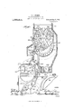
- Figure 1 is a view partly in elevation and partly in vertical section showing the casing of a gin feeder and the operative mechanism.
- Fig. 2 is a detail view showing a part of the variable feed mechanism.
- Fig. 3 is a further detail showing the elements of Fig. 2 under different conditions.
- Fig. 4 is an elevation of a bracket for carrying the shafts and gears of the feeding mechanism.
- Fig. 5 is a top plan View of one of the lever arms shown in Figs. 2 and 3, and constituting a part of the feed mechanism.
- Fig. 6 is a plan View of a cam lever for operating the arm shown in Fig. 5.
- Fig. 7 is a detail view of a bracket mounted adjacent to the roll box of the gin.
- Fig. 8 is a further detail of mechanism hereafter described.
- a casing 10 for the gin feeding device which casing may be of any suitable construction, and mount therein a picker roll said roll being carried by shaft 16 driven by suitable mechanism not shown.
- a screen 17 is located within the casing and is of substantially the form shown in Fig. 1, a portion of the screen conforming to the configuration of the roll 15.
- the several rolls and gears of the gin feeder are mounted in brackets 12 shown in Fig. 4 which are disposed on the sides of the casing 10.
- Shaft 16 carries a friction roll 20 which may be made of paper or other suitable substance and said roll 20 engages the inner portion of the rim of wheel 21 mounted on shaft 22 and having its bearing in the frame above mentioned.
- a pinion 24 rotates with wheel 21 and engages the teeth. of wheel 25 mounted on shaft 26 carrying a pinion 27 meshing with a gear 28.
- the gear last mentioned is carried on shaft 29 of the feed roll 30.
- a corresponding feed roll 31 is carried upon shaft 32 and is driven by gear 33 meshing with gear 28 above mentioned.
- a plate 48 is adjustably secured to the casing in any suitable manner and to the central portion thereof a lever arm 49 is pivoted, which arm carries a cam 50 clesigned to bear against the lower curved surface of arm 42.
- the lever arm is shown as being provided with a boss 51 having engagement with a leather washer 52, this washer coming into contact with a corresponding boss 53 on the plate 48.
- Cam 50 controls the operation of lever 42 under certain conditions and thereby controls the rate of feed of the cotton.
- the roll box 38 is provided at the ends with heads 39, and the saw cylinder is mounted on shaft carried by the framework 56.
- the roll box is pivoted at 57, and is swung outwardly when desired by means of arm 58 secured at point 59.
- Bracket 61 Rigidly connected with a lever 60 is a bracket 61 provided with a slot 62, the bracket and the arm being pivoted at 61. Slot 62 is engaged by a pin 63 carried on lever 64 having a weight 65 on one end thereof. of the cotton in the roll box, and the movement of the weight and lever is limited by stops 64.
- a float 66 is arranged within the roll box and is carried by a bar 67 in bearing members provided in the walls of the roll box. Lever Gel is pivoted at the same point, designated 67 in the drawings.
- Bracket 61 is shown in detail in F ig. 7 and the mounting of the bar 67 is illustrated in Fig. 8. Arm 60 is provided with an adjustable screw 69 at its upper end. The operation of this construction will be described below.
- a conveyer 68 is mounted, and serves to carry olf the dust and trash collecting in that portion.
- Air blast pipeTO is provided with a suitable nozzle 71 and the lint flue is shown at
- a plurality of driven members and driving means for the same said driving means including a wheel and a plurality of rollers one of which is eccentrically mounted and the second of which is caused to have contact with the wheel at regular intervals.
- a plurality of driven members driving means therefor, said driving means including a wheel and a plurality of rollers one .of which is eccentrically mounted and the other of which is caused to have contact with said wheel at given intervals during the revolution of the eccentrically mounted roller, and means for varying the said intervals.
- a plurality of driven members a plurality of levers pivotally connected at one end, a driving shaft, a roller carried by one of the levers, a Wheel for imparting motion to the driven members, an eccentrically mounted roller held in contact With said driving shaft, and adjusting means for causing the first mentioned roller to have contact With said Wheel for a given interval during the rotation of the eccentrically mounted roller.
- a plurality of rotating members having contact with each other under given conditions, and means including an adjustably mounted eccentric device controlling the position of one of said members and varying the periods of contact.
- a driven member means including an eccentrically mounted device for imparting I110- tion to the driven member during a given portion of a complete rotation of the eccentrically mounted device, and a pivoted lever for carrying the device last mentioned.
- a driven member means including an eccentrically mounted device for imparting motion to the driven member during a given portion of a complete rotation of the eccentrically mounted device, a pivoted lever carrying the device last mentioned, and means controlling the lever.
Description
T. S. GRIMES.
VARIABLE SPEED MECHANISM.
APPLICATION rum) FEB. 21, 1912.
COLUMBIA PLANOGRAPH ISO-,WASHINGTON, D. c.
Patented Aug. 5, 1913.
3 SHEETSSHEET l.
Zhwentor T. S. GRIMES VARIABLE SPEED MECHANISM.
APPLIUATION FILED FEB. 21, 1912.
Patented Aug. 5, 1913,,
3 SHEETS-SHEET 2.
3nventor (meme/gs COLUMBIA PLANOGRAPH c0. WASHINGTON. D, c.
T. S. GRIMES.
VARIABLE SPEED MECHANISM.
APPLIGATION FILED FEB. 21, 1912.
1,969,14. Patented Aug; 5, 1913.
3 SHEETS-'SHEET 3.
V a i (Wornegs COLUMBIA PLANDCIRAPH CO.,WASHINGTON, D.'c,
T111 err THADIDEUS S. GRIMES, OF COLUMBUS, GEORGIA, ASSIGNOR TO LUIVIMUS COTTON GIN 00., OF MUSGOGEE COUNTY, GEORGIA, A CORPORATION OF GEORGIA.
VARIABLE-SPEED MECHANISM.
Original application filed July 5, 1911, Serial No. 637,019.
Specification of Letters Patent.
1912. Serial No. 679,163.
To all whom it may concern:
Be it known that I, TIIADDEUS S. GRIMEs, a citizen of the United States, residing at Columbus, in the county of Muscogee and State of Georgia, have invented certain new and useful Improvements in Variable-Speed Mechanism; and I do hereby declare the following to be a full, clear, and exact description of the invention, such as will enable others skilled in the art to which it appertains to make and use the same.
This invention relates to variable speed mechanism and to mechanism of the character mentioned which is especially applicable to cotton gins, linters and the like, but which is not limited to such use.
The present application is a division of my application filed July 5, 1911, Serial No. 637,019, in which the objects of the device as a whole are fully set forth.
In the accompanying drawings, Figure 1 is a view partly in elevation and partly in vertical section showing the casing of a gin feeder and the operative mechanism. Fig. 2 is a detail view showing a part of the variable feed mechanism. Fig. 3 is a further detail showing the elements of Fig. 2 under different conditions. Fig. 4 is an elevation of a bracket for carrying the shafts and gears of the feeding mechanism. Fig. 5 is a top plan View of one of the lever arms shown in Figs. 2 and 3, and constituting a part of the feed mechanism. Fig. 6 is a plan View of a cam lever for operating the arm shown in Fig. 5. Fig. 7 is a detail view of a bracket mounted adjacent to the roll box of the gin. Fig. 8 is a further detail of mechanism hereafter described.
In carrying out my invention I provide a casing 10 for the gin feeding device, which casing may be of any suitable construction, and mount therein a picker roll said roll being carried by shaft 16 driven by suitable mechanism not shown. A screen 17 is located within the casing and is of substantially the form shown in Fig. 1, a portion of the screen conforming to the configuration of the roll 15.
The several rolls and gears of the gin feeder are mounted in brackets 12 shown in Fig. 4 which are disposed on the sides of the casing 10. Shaft 16 carries a friction roll 20 which may be made of paper or other suitable substance and said roll 20 engages the inner portion of the rim of wheel 21 mounted on shaft 22 and having its bearing in the frame above mentioned. A pinion 24 rotates with wheel 21 and engages the teeth. of wheel 25 mounted on shaft 26 carrying a pinion 27 meshing with a gear 28. The gear last mentioned is carried on shaft 29 of the feed roll 30. A corresponding feed roll 31 is carried upon shaft 32 and is driven by gear 33 meshing with gear 28 above mentioned.
The cotton within the upper portion 35 of the casing is brought into engagement with the feed rolls and carried downwardly be tween the latter coming into engagement with the spikes of picker roll 15 and passing along the surface of screen 17 is cleaned and passes thence through the opening 36 into the apron 37 and into the roll box 38 of the gin. In order to provide for the suitable regulation of the feed I have devised a construction by means of which motion is imparted to wheel 21in a greater or less degree as circumstances may require. An arm 40 is pivoted at 41 and has pivotal connection with a forked arm 42, these arms being secured at the point 41 and being permitted to have vibration at their free ends which are connected by means of a coil spring 43. A roll 44 is eccentrically mounted at 45 on arm 42 and this roll bears against shaft 16 carrying friction roll 20.
A plate 48 is adjustably secured to the casing in any suitable manner and to the central portion thereof a lever arm 49 is pivoted, which arm carries a cam 50 clesigned to bear against the lower curved surface of arm 42. In Fig. 6 the lever arm is shown as being provided with a boss 51 having engagement with a leather washer 52, this washer coming into contact with a corresponding boss 53 on the plate 48. Cam 50 controls the operation of lever 42 under certain conditions and thereby controls the rate of feed of the cotton. By virtue of the eccentric mounting of roll 44 in lever 42, and the adjustment of cam 50, the driving contact between 20 and 21 can be made continuous, or it can be discontinued during all or part of each revolution of roll 44. Other means for controlling lever 42 are also provided.
The roll box 38 is provided at the ends with heads 39, and the saw cylinder is mounted on shaft carried by the framework 56. The roll box is pivoted at 57, and is swung outwardly when desired by means of arm 58 secured at point 59.
Rigidly connected with a lever 60 is a bracket 61 provided with a slot 62, the bracket and the arm being pivoted at 61. Slot 62 is engaged by a pin 63 carried on lever 64 having a weight 65 on one end thereof. of the cotton in the roll box, and the movement of the weight and lever is limited by stops 64. A float 66 is arranged within the roll box and is carried by a bar 67 in bearing members provided in the walls of the roll box. Lever Gel is pivoted at the same point, designated 67 in the drawings. Bracket 61 is shown in detail in F ig. 7 and the mounting of the bar 67 is illustrated in Fig. 8. Arm 60 is provided with an adjustable screw 69 at its upper end. The operation of this construction will be described below. In the lower part of casing 10 a conveyer 68 is mounted, and serves to carry olf the dust and trash collecting in that portion. Air blast pipeTOis provided with a suitable nozzle 71 and the lint flue is shown at 72.
When the speed regulating devices are in the position shown in Fig. 1, about onehalf of the full feed is provided. It will be observed that the handle of cam 50 is turned to the left, and that arm 60 is in a vertical position, the upper-end thereof being under the central portion of lever arm-42. The position of full feed is shown in Fig. Roll at being eccentrically mounted, and arm L2 being free to vibrate as the result of frictional contact between the several rotating members, there will be continuous contact between roll 20 and the rim of wheel 21, and therefore a maximum speed. The weight of the picker roll is carried on shaft 16, causing arm 40 to remain in the position shown in Fig. 2. In Fig. 3 there will be no feed because lever arm 42 is fixedly supported at its left hand end by cam 50,
-' to its highest position), by means of cam 50 or arm 60. When thus raised, arms 40 5 and 42 will be causedato vibrate, and roller 5 20 will be lifted from the rim of wheel 21 at regular intervals. These periods of contact will increase if cam 50 is turned toward 5 the position shown in Fig. 2 (the upper arm The weight controls the density tation of bar 67) and causing pin 63 to press downward 1n slot 62, throwmg arm 60 toward the required position to decrease the; rate of feed. The position of weight 65 controls the density of the roll of cotton in the roll box. In swinging the roll box forward, to stop ginning, pin 63 causes the movement of bracket 62 and of arm 60,
throwing the latterto the no feed position, shown in Fig. '3. The reverse operation of these parts, starts the feed automatically.
What I claim as new and desire to secure by Letters .Patent is:
1. In a device of the class described, a plurality of driven members and driving means for the same, said driving means including a wheel and a plurality of rollers one of which is eccentrically mounted and the second of which is caused to have contact with the wheel at regular intervals.
2. In a device of the class described, a plurality of driven members, driving means therefor, said driving means including a wheel and a plurality of rollers one .of which is eccentrically mounted and the other of which is caused to have contact with said wheel at given intervals during the revolution of the eccentrically mounted roller, and means for varying the said intervals.
3. In a device of the class described, a plurality of driven members, a driving shaft, a plurality of levers pivoted at oneend, a roller carried by one of the levers, a wheel for imparting motion to the driven members, and means for causing the roller carried by one of the .leversto bear .against said wheel for a given interval during the rotation of the driving shaft.
4. Ina device of the class described, a plurality of driven members, a driving shaft,
a plurality of levers pivoted at one end, a roller carried b one of the levers, a wheel for imparting motion to the driven members, and eccentrically mounted means for causing the first mentioned roller to bear against said wheel for .a given interval during the revolution of the eccentrically mounted means.
5. In a device of the class described, a plurality of driven members, a driving shaft,
a plurality of levers pivoted at one end, a 1.30
spring connected with the opposite ends of the levers, a roller carried by one of the levers, a Wheel for imparting motion to the driven members, and means for causing the said roller carried by one of the levers to bear against said Wheel for a given interval during the revolution of the roller.
6. In a device of the class described, a plurality of driven members, a plurality of levers pivotally connected at one end, a driving shaft, a roller carried by one of the levers, a Wheel for imparting motion to the driven members, an eccentrically mounted roller held in contact With said driving shaft, and adjusting means for causing the first mentioned roller to have contact With said Wheel for a given interval during the rotation of the eccentrically mounted roller.
7. In a device of the class described, a plurality of rotating members having contact with each other under given conditions, and means including an adjustably mounted eccentric device controlling the position of one of said members and varying the periods of contact.
8. In a device of the class described, a driven member, means including an eccentrically mounted device for imparting I110- tion to the driven member during a given portion of a complete rotation of the eccentrically mounted device, and a pivoted lever for carrying the device last mentioned.
9. In a device of the class described, a driven member, means including an eccentrically mounted device for imparting motion to the driven member during a given portion of a complete rotation of the eccentrically mounted device, a pivoted lever carrying the device last mentioned, and means controlling the lever.
In testimony whereof I aifix my signature in presence of two Witnesses.
THADDEUS S. GRIMES.
WVitnesses:
WM. F. LUPo, K. Rosoon LUMMUs.
Copies of this patent may be obtained for five cents each, by addressing the Commissioner of Patents,
Washington, D. C.
Priority Applications (1)
| Application Number | Priority Date | Filing Date | Title |
|---|---|---|---|
| US679163A US1069414A (en) | 1911-07-05 | 1912-02-21 | Variable-speed mechanism. |
Applications Claiming Priority (2)
| Application Number | Priority Date | Filing Date | Title |
|---|---|---|---|
| US63701911A US1069413A (en) | 1911-07-05 | 1911-07-05 | Variable-feed mechanism for cotton-gins. |
| US679163A US1069414A (en) | 1911-07-05 | 1912-02-21 | Variable-speed mechanism. |
Publications (1)
| Publication Number | Publication Date |
|---|---|
| US1069414A true US1069414A (en) | 1913-08-05 |
Family
ID=3137651
Family Applications (1)
| Application Number | Title | Priority Date | Filing Date |
|---|---|---|---|
| US679163A Expired - Lifetime US1069414A (en) | 1911-07-05 | 1912-02-21 | Variable-speed mechanism. |
Country Status (1)
| Country | Link |
|---|---|
| US (1) | US1069414A (en) |
-
1912
- 1912-02-21 US US679163A patent/US1069414A/en not_active Expired - Lifetime
Similar Documents
| Publication | Publication Date | Title |
|---|---|---|
| US1069414A (en) | Variable-speed mechanism. | |
| US1069413A (en) | Variable-feed mechanism for cotton-gins. | |
| US299297A (en) | van winkle | |
| US415684A (en) | Island | |
| US392275A (en) | The sliveb in sliver boxes of carding | |
| US823439A (en) | Gin. | |
| US269305A (en) | Cotton-gin | |
| US1180131A (en) | Cotton-cleaner. | |
| US1034996A (en) | Blend-making machine for staple goods. | |
| US766052A (en) | Cotton-gin feeder. | |
| US305228A (en) | Cotton-gins | |
| US540265A (en) | And octave gilbert | |
| US498454A (en) | Machine for cutting tobacco | |
| US1180132A (en) | Cotton-cleaner. | |
| US817607A (en) | Ginning or burring machine. | |
| US603845A (en) | Corn-husking machine | |
| US92705A (en) | Improvement in machine for feeding wool | |
| GB191117485A (en) | Improvements in Feeding Machines for Carding Engines and the like. | |
| US822550A (en) | Doffer-comb motion. | |
| US218797A (en) | Improvement in rope-spinning machinery | |
| US696959A (en) | Cotton-seed delinter. | |
| US1202699A (en) | Cotton-gin of the saw type. | |
| US279720A (en) | crovson | |
| US1003543A (en) | Dough-dividing machine. | |
| US125564A (en) | Improvement in machines for winding bobbins |