US10694087B2 - Output apparatus, lens apparatus, adaptor apparatus, camera apparatus, and image pickup apparatus - Google Patents
Output apparatus, lens apparatus, adaptor apparatus, camera apparatus, and image pickup apparatus Download PDFInfo
- Publication number
- US10694087B2 US10694087B2 US15/955,889 US201815955889A US10694087B2 US 10694087 B2 US10694087 B2 US 10694087B2 US 201815955889 A US201815955889 A US 201815955889A US 10694087 B2 US10694087 B2 US 10694087B2
- Authority
- US
- United States
- Prior art keywords
- correction data
- correction
- combinations
- optical correction
- correction information
- Prior art date
- Legal status (The legal status is an assumption and is not a legal conclusion. Google has not performed a legal analysis and makes no representation as to the accuracy of the status listed.)
- Active
Links
Images


Classifications
-
- G—PHYSICS
- G02—OPTICS
- G02B—OPTICAL ELEMENTS, SYSTEMS OR APPARATUS
- G02B27/00—Optical systems or apparatus not provided for by any of the groups G02B1/00 - G02B26/00, G02B30/00
- G02B27/0025—Optical systems or apparatus not provided for by any of the groups G02B1/00 - G02B26/00, G02B30/00 for optical correction, e.g. distorsion, aberration
- G02B27/0068—Optical systems or apparatus not provided for by any of the groups G02B1/00 - G02B26/00, G02B30/00 for optical correction, e.g. distorsion, aberration having means for controlling the degree of correction, e.g. using phase modulators, movable elements
-
- H—ELECTRICITY
- H04—ELECTRIC COMMUNICATION TECHNIQUE
- H04N—PICTORIAL COMMUNICATION, e.g. TELEVISION
- H04N23/00—Cameras or camera modules comprising electronic image sensors; Control thereof
- H04N23/50—Constructional details
- H04N23/55—Optical parts specially adapted for electronic image sensors; Mounting thereof
-
- H04N5/2254—
-
- G—PHYSICS
- G02—OPTICS
- G02B—OPTICAL ELEMENTS, SYSTEMS OR APPARATUS
- G02B27/00—Optical systems or apparatus not provided for by any of the groups G02B1/00 - G02B26/00, G02B30/00
- G02B27/0025—Optical systems or apparatus not provided for by any of the groups G02B1/00 - G02B26/00, G02B30/00 for optical correction, e.g. distorsion, aberration
- G02B27/0037—Optical systems or apparatus not provided for by any of the groups G02B1/00 - G02B26/00, G02B30/00 for optical correction, e.g. distorsion, aberration with diffracting elements
-
- G—PHYSICS
- G02—OPTICS
- G02B—OPTICAL ELEMENTS, SYSTEMS OR APPARATUS
- G02B7/00—Mountings, adjusting means, or light-tight connections, for optical elements
- G02B7/02—Mountings, adjusting means, or light-tight connections, for optical elements for lenses
- G02B7/04—Mountings, adjusting means, or light-tight connections, for optical elements for lenses with mechanism for focusing or varying magnification
-
- G06K9/00604—
-
- G—PHYSICS
- G06—COMPUTING OR CALCULATING; COUNTING
- G06V—IMAGE OR VIDEO RECOGNITION OR UNDERSTANDING
- G06V40/00—Recognition of biometric, human-related or animal-related patterns in image or video data
- G06V40/10—Human or animal bodies, e.g. vehicle occupants or pedestrians; Body parts, e.g. hands
- G06V40/18—Eye characteristics, e.g. of the iris
- G06V40/19—Sensors therefor
-
- H—ELECTRICITY
- H04—ELECTRIC COMMUNICATION TECHNIQUE
- H04N—PICTORIAL COMMUNICATION, e.g. TELEVISION
- H04N23/00—Cameras or camera modules comprising electronic image sensors; Control thereof
- H04N23/50—Constructional details
- H04N23/54—Mounting of pick-up tubes, electronic image sensors, deviation or focusing coils
-
- H—ELECTRICITY
- H04—ELECTRIC COMMUNICATION TECHNIQUE
- H04N—PICTORIAL COMMUNICATION, e.g. TELEVISION
- H04N23/00—Cameras or camera modules comprising electronic image sensors; Control thereof
- H04N23/60—Control of cameras or camera modules
- H04N23/66—Remote control of cameras or camera parts, e.g. by remote control devices
- H04N23/663—Remote control of cameras or camera parts, e.g. by remote control devices for controlling interchangeable camera parts based on electronic image sensor signals
-
- H—ELECTRICITY
- H04—ELECTRIC COMMUNICATION TECHNIQUE
- H04N—PICTORIAL COMMUNICATION, e.g. TELEVISION
- H04N25/00—Circuitry of solid-state image sensors [SSIS]; Control thereof
- H04N25/60—Noise processing, e.g. detecting, correcting, reducing or removing noise
- H04N25/61—Noise processing, e.g. detecting, correcting, reducing or removing noise the noise originating only from the lens unit, e.g. flare, shading, vignetting or "cos4"
- H04N25/611—Correction of chromatic aberration
-
- H04N5/2178—
-
- H04N5/2253—
-
- H04N5/23209—
-
- H04N5/3572—
-
- H—ELECTRICITY
- H04—ELECTRIC COMMUNICATION TECHNIQUE
- H04N—PICTORIAL COMMUNICATION, e.g. TELEVISION
- H04N23/00—Cameras or camera modules comprising electronic image sensors; Control thereof
- H04N23/60—Control of cameras or camera modules
- H04N23/67—Focus control based on electronic image sensor signals
-
- H04N5/23212—
Definitions
- the present invention relates to an output apparatus, a lens apparatus, an adaptor apparatus, a camera apparatus, and an image pickup apparatus.
- Digital cameras or other such image pickup apparatus are used for various purposes, and there is an increasing demand for higher image quality in images output from such image pickup apparatus.
- image degradation due to optical characteristics of an image pickup lens used for imaging an object.
- optical characteristics that cause image degradation include peripheral darkening, a distortion, and a chromatic aberration of magnification.
- Those optical characteristics differ depending on the optical system of a lens unit.
- optical correction for correcting such image degradation by image processing.
- a lens unit which is configured to retain data regarding optical characteristics (optical correction data) in the lens unit, and to transfer the optical correction data to an image pickup apparatus.
- a method of determining, by the image pickup apparatus, a correction amount for image processing through use of the optical correction data and image pickup condition information on the lens unit is determined based on the optical parameters of optical adjustment members for the zoom, focus, and iris of the lens unit.
- a lens unit which is configured to retain optical correction data for each of discretely formed image pickup conditions (reference image pickup conditions) instead of retaining optical correction data for all the image pickup conditions in the lens unit in order to reduce the size of the optical correction data.
- reference image pickup conditions discretely formed image pickup conditions
- approximate interpolation is performed based on the optical correction data for the reference image pickup condition to determine a correction amount for the image processing.
- an invention aiming at reduction in load of communication between a lens unit and an image pickup apparatus. Specifically, there is proposed a method involving selecting partial data from optical correction data retained by the lens unit depending on information regarding an image pickup element provided to the image pickup apparatus, and determining a correction amount for image processing through use of the selected partial data.
- the present invention provides, for example, an output apparatus advantageous in reduction in data size and highly accurate image correction.
- an output apparatus which is configured to output correction information on combinations each of which is a combination of a value of a parameter of an optical system and correction data corresponding to the value, the optical system forming an image to be picked up by a camera apparatus, the information being used for determining a correction amount regarding an optical characteristic of the optical system
- the output apparatus including: a memory; and a processor configured to determine the correction information based on information regarding the camera apparatus, in which the processor is configured to determine, letting M and N be positive integers that satisfy M ⁇ N, the correction information in a case where a number of the combinations is M so as to include information on a combination of the value and the correction data that is not included in combinations of the correction information in a case where a number of the combinations is N, and in which the memory stores the correction information in the case where the number of the combinations is N.
- FIG. 1 is a configuration block diagram in a first embodiment of the present invention.
- FIG. 2 is an operation flow chart of a camera apparatus 11 according to the first embodiment.
- FIG. 3 is a structure diagram of optical correction data.
- FIG. 4 is an operation flow chart of a lens unit 10 in the first embodiment.
- FIG. 5A is a graph for showing a relationship among optical correction data Dl, optical correction data Do, and optical correction data Dc in terms of an n-th order coefficient Pn of an aberration quantity calculation formula.
- FIG. 5B is a graph for showing a relationship among the optical correction data Dl, the optical correction data Do, and the optical correction data Dc in terms of the n-th order coefficient Pn of the aberration quantity calculation formula.
- FIG. 6 is a graph for showing a method of determining an iris division point for the n-th order coefficient Pn of the aberration quantity calculation formula on the optical correction data Dc.
- FIG. 7 is a graph for showing a relationship among magnification chromatic aberration quantities Er calculated from the optical correction data Dl, the optical correction data Do, and the optical correction data Dc.
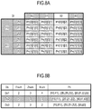
- FIG. 8A is a data structure table of the optical correction data Dl in terms of the n-th order coefficient Pn of the aberration quantity calculation formula in an embodiment of a related art.
- FIG. 8B is a data structure table of the optical correction data Dl in terms of the n-th order coefficient Pn of the aberration quantity calculation formula in the embodiment of the related art.
- FIG. 9A is a table for showing a first example of a data structure of the optical correction data Dl in terms of the n-th order coefficient Pn of the aberration quantity calculation formula in the first embodiment.
- FIG. 9B is a table for showing the first example of the data structure of the optical correction data Dl in terms of the n-th order coefficient Pn of the aberration quantity calculation formula in the first embodiment.
- FIG. 9C is a table for showing the first example of the data structure of the optical correction data Dl in terms of the n-th order coefficient Pn of the aberration quantity calculation formula in the first embodiment.
- FIG. 9D is a table for showing the first example of the data structure of the optical correction data Dl in terms of the n-th order coefficient Pn of the aberration quantity calculation formula in the first embodiment.
- FIG. 10A is a table for showing a second example of the data structure of the optical correction data Dl in terms of the n-th order coefficient Pn of the aberration quantity calculation formula in the first embodiment.
- FIG. 10B is a table for showing the second example of the data structure of the optical correction data Dl in terms of the n-th order coefficient Pn of the aberration quantity calculation formula in the first embodiment.
- FIG. 11 is a configuration block diagram in a second embodiment of the present invention.
- FIG. 12 is an operation flow chart of a camera apparatus 21 according to the second embodiment.
- FIG. 13 is an operation flow chart of a lens unit 20 in the second embodiment.
- FIG. 14 is a configuration block diagram in a third embodiment of the present invention.
- FIG. 15 is an operation flow chart of an adaptor unit 31 in the third embodiment.
- the description of the first embodiment is directed to a case in which optical correction is performed in order to correct a chromatic aberration of magnification.
- FIG. 1 is a configuration block diagram in the first embodiment.
- a lens unit (lens apparatus and optical system) 10 is a lens unit configured to control a movable optical member relating to image pickup.
- a camera apparatus 11 is an image pickup apparatus configured to pick up an image, and is connected to the lens unit 10 .
- a focus lens 101 is a focus lens for focusing a picked-up image.
- a zoom lens 102 is a zoom lens for zooming the picked-up image.
- An iris 103 is an iris for adjusting a light amount of the picked-up image.
- a focus lens position detector 104 is a focus lens position detector configured to detect the position of the focus lens.
- the zoom lens position detector 105 is a zoom lens position detector configured to detect the position of the zoom lens.
- An iris position detector 106 is an iris position detector configured to detect the position of the iris.
- an absolute encoder is used as each of the focus lens position detector 104 , the zoom lens position detector 105 , and the iris position detector 106 .
- An image pickup condition determiner 107 is an image pickup condition determiner configured to determine an image pickup condition for the lens unit 10 from the result of detecting the position by each of the focus lens position detector 104 , the zoom lens position detector 105 , and the iris position detector 106 .
- the image pickup condition represents, for example, a value obtained by normalizing each of a focus lens position, a zoom lens position, an iris position within a movable range thereof.
- a lens optical correction data memory 108 is a data memory configured to retain optical correction data (basic data), and is a non-volatile memory, for example, a flash ROM memory.
- the optical correction data is data to be used for calculating a magnification chromatic aberration quantity ascribable to the optical characteristics of the lens unit 10 .
- An optical correction data determiner 109 is an optical correction data determiner configured to determine optical correction data to be sent to the camera apparatus 11 in accordance with the camera apparatus 11 .
- a lens-apparatus communication unit 110 is a communication unit configured to communicate to/from the camera apparatus 11 .
- the image pickup condition determiner 107 , the optical correction data determiner 109 , and the lens-apparatus communication unit 110 are provided inside, for example, a CPU within the lens unit 10 .
- An image pickup element 111 is an image pickup element configured to receive an optical image formed by the lens unit to pick up an image as a picked-up image, and is, for example, a CMOS image sensor.
- An image data generator 112 is an image data generator configured to generate picked-up image data.
- a camera information memory 113 is a data memory configured to retain the camera information.
- the camera information (image pickup apparatus information) represents the size of data that can be retained by a camera optical correction data memory 115 (that is available for correction processing), the image size, number of effective pixels, and permissible circle of confusion of the image pickup element 111 , and other such information relating to a camera apparatus.
- a camera-apparatus communication unit 114 is a communication unit configured to communicate to/from the lens unit 10 .
- the camera optical correction data memory 115 is a data memory configured to retain the optical correction data of the lens unit 10 , and is a non-volatile memory, for example, a flash ROM memory.
- a correction amount determiner 116 determines a correction amount from the optical correction data and the image pickup condition.
- An image processor (image processing unit) 117 is an image processor configured to perform image processing on the picked-up image.
- the image data generator 112 , the camera information memory 113 , the camera-apparatus communication unit 114 , the correction amount determiner 116 , and the image processor 117 are provided inside, for example, a CPU within the camera apparatus 11 .
- An image display 118 is an image display configured to display an image picked up by the camera apparatus 11 , and is, for example, a liquid crystal monitor.
- light that has entered the lens unit 10 is output as an image subjected to optical correction in accordance with the following flow.
- the light that has entered the lens unit 10 passes through the focus lens 101 , the zoom lens 102 , and the iris 103 to be imaged on the image pickup element 111 , and is converted into an electric signal to be output from the image data generator 112 to the image processor 117 as image data before optical correction.
- the image processor 117 subjects the image data before optical correction to image processing based on an optical correction amount Rr determined by the correction amount determiner 116 , and outputs the resultant to the image display 118 as image data after optical correction.
- an image obtained by correcting a magnification chromatic aberration quantity Er ascribable to the optical characteristics of the lens unit 10 is displayed on the image display 118 .
- Step S 201 When the lens unit 10 is connected to the camera apparatus 11 and the camera apparatus 11 is powered on, the procedure advances from Step S 201 to Step S 202 to start an operation in the first embodiment.
- the lens unit 10 is configured to be supplied with power via a contact (not shown) with the camera apparatus 11 , and hence, when the camera apparatus 11 is powered on, the lens unit 10 is simultaneously supplied with power to be activated.
- the camera information memory 113 sends the camera information (image pickup apparatus information) to the lens unit 10 via the camera-apparatus communication unit 114 , and the procedure advances to Step S 203 .
- the camera-apparatus communication unit 114 receives optical correction data Dc for the camera apparatus 11 from the lens unit 10 , and the procedure advances to Step S 204 .
- the optical correction data Dc includes information on the number of division, division point information, information on a coefficient of an aberration quantity calculation formula.
- the information on the number of division represents a number into which the focus lens position, the zoom lens position, and the iris position, which are optical parameters, are freely divided within the movable range.
- the division point information represents positions at which the focus lens position, the zoom lens position, and the iris position are freely divided within the movable range. For example, when the number of focus division, the number of zoom division, and the number of iris division are Fnum, Znum, and Inum, respectively, the number of focus division points, the number of zoom division points, and the number of iris division points are Fnum, Znum, and Inum, respectively.
- the information on the coefficient of the aberration quantity calculation formula represents coefficients of a multidimensional formula for calculating the magnification chromatic aberration quantity Er with respect to an image height (optical parameter) h in an image of another color (R image) with an image of a given color (G image) being used as a reference.
- an image height (optical parameter) h in an image of another color (R image) with an image of a given color (G image) being used as a reference When the magnification chromatic aberration quantity of an image of another color (magnification chromatic aberration quantity of a B image with the G image being used as a reference) is calculated, another coefficient of the aberration quantity calculation formula is required, but the basic flow is the same, and hence the detailed description thereof is omitted.
- the number of coefficients of the aberration quantity calculation formula is (n+1) ⁇ Fnum ⁇ Znum ⁇ Inum.
- the magnification chromatic aberration quantity Er with respect to the image height h is as expressed in Formula 1.
- Step S 204 the camera optical correction data memory 115 internally records the optical correction data Dc for the camera apparatus 11 received in Step S 203 , and the procedure advances to Step S 205 .
- Step S 205 the camera-apparatus communication unit 114 receives the current image pickup condition from the lens unit 10 , and the procedure advances to Step S 206 .
- the correction amount determiner 116 determines the optical correction amount Rr based on the current image pickup condition received in Step S 205 and the optical correction data Dc for the camera apparatus 11 recorded in the camera optical correction data memory 115 .
- an approximate correction formula coefficient for the image pickup condition is determined from correction formula coefficients for the focus division point, the zoom division point, and the iris division point, which are close to the current image pickup condition acquired in Step S 205 , through linear interpolation (interpolation processing) between dividing points, and Formula 1 is used to determine the magnification chromatic aberration quantity Er.
- Step S 205 and Step S 206 are successively executed, to thereby be able to continue to determine the optical correction amount Rr to be applied to the image data before optical correction.
- FIG. 4 is an illustration of the flow of the series of processing steps performed on the lens unit 10 side with respect to the processing of FIG. 2 in the first embodiment.
- Step S 201 to Step S 202 the lens unit 10 is also powered on, and the procedure advances from Step S 401 to Step S 402 to start the operation of the lens unit 10 of the first embodiment.
- the lens-apparatus communication unit 110 receives the camera information sent from the camera apparatus 11 in Step S 202 , and the procedure advances to Step S 403 .
- the optical correction data determiner 109 determines the optical correction data Dc for the camera apparatus 11 based on the camera information received in Step S 402 and optical correction data Dl retained by the lens optical correction data memory 108 , and the procedure advances to Step S 404 .
- a method of determining the optical correction data Dc for the camera apparatus 11 is described later.
- the optical correction data determiner 109 sends the optical correction data Dc for the camera apparatus 11 determined in Step S 403 to the camera apparatus 11 via the lens-apparatus communication unit 110 , and the procedure advances to Step S 405 .
- the image pickup condition determiner 107 determines the image pickup condition for the lens unit 10 from the result of detecting the position by each of the focus lens position detector 104 , the zoom lens position detector 105 , and the iris position detector 106 , and the procedure advances to Step S 406 .
- Step S 406 the image pickup condition determiner 107 sends the current image pickup condition determined in Step S 405 to the camera apparatus 11 via the lens-apparatus communication unit 110 .
- Step S 405 and Step S 406 are successively executed, to thereby be able to continue to send the current image pickup condition, which is required for the calculation of the optical correction amount Rr to be applied, to the camera apparatus 11 .
- the optical correction amount Rr is determined, and such an image as to cancel the magnification chromatic aberration quantity Er is displayed on the image display 118 .
- FIG. 5A is a graph for showing a relationship between the n-th order coefficient Pn of the aberration quantity calculation formula and the iris position on each of the optical correction data Dl and optical correction data Do.
- the optical correction data Do is the optical correction data of the camera apparatus 11 determined through thinning-out being a related art.
- FIG. 5A there is shown a case in which the optical correction data. Do has a smaller number of iris division by one than the number Inum of iris division of the optical correction data Dl due to the small size of data that can be retained by the camera optical correction data memory 115 .
- the vertical axis represents the n-th order coefficient Pn of the aberration quantity calculation formula
- the horizontal axis represents the iris position
- FIG. 5A there is shown a case in which a focus position and a zoom position are fixed at freely-set division point positions, and the number Inum of iris division of the optical correction data Dl is 4.
- Il 0 to Il 3 represent the respective positions of the iris division points on the optical correction data Dl
- Pnl 0 to Pnl 3 represent the respective values of the n-th order coefficients Pn of the aberration quantity calculation formula at the iris division points Il 0 to Il 3
- the optical correction data Do represents the optical correction data obtained by thinning out the division point Il 2 from the optical correction data Dl. At this time, the number Inum of iris division of the optical correction data Do is 3.
- the n-th order coefficient Pn of the aberration quantity calculation formula at an iris position different from the division point is calculated by linear approximation from the n-th order coefficients Pn of the aberration quantity calculation formula at the adjacent iris division points. Therefore, the relationship between the n-th order coefficient Pn of the aberration quantity calculation formula and the iris position on the optical correction data DI is as indicated by the dotted line in FIG. 5A . In the same manner, the relationship between the n-th order coefficient Pn of the aberration quantity calculation formula and the iris position on the optical correction data Do is as indicated by the solid line in FIG. 5A .
- the hatched portion indicates a difference at each iris position between the n-th order coefficients Pn of the aberration quantity calculation formula on the optical correction data. Dl and the optical correction data Do.
- the hatched portion becomes smaller and as the maximum value of the differences between the n-th order coefficients Pn of the aberration quantity calculation formula on the optical correction data Dl and the optical correction data Do over the entire range of the iris positions Il 0 to Il 3 becomes smaller, a difference between the magnification chromatic aberration quantity Er calculated by Formula 1 and the magnification chromatic aberration quantity of the image data after optical correction becomes smaller. In short, accuracy in correction of the chromatic aberration of magnification becomes higher.
- FIG. 5B is a graph for showing a relationship between the n-th order coefficient Pn of the aberration quantity calculation formula and the iris position on each of the optical correction data Dl and the optical correction data Dc.
- the optical correction data Dc is the optical correction data of the camera apparatus 11 to which the first embodiment is applied.
- FIG. 5A in order to reduce the optical correction data, the division point 112 is thinned out from the optical correction data Do.
- FIG. SB differs from FIG. 5A in that Ix is newly set on the optical correction data Dc in place of Il 1 and Il 2 .
- the n-th order coefficient Pn of the aberration quantity calculation formula at Ix is Pncx.
- the iris division points on the optical correction data Dc are Il 0 , Ix, and Il 3 , and hence the number Inum of iris division is 3, which is the same as the number Inum of iris division of the optical correction data Dl.
- a difference Pec 2 between the n-th order coefficient Pnl 2 of the aberration quantity correction formula on the optical correction data Dl at Il 2 and an n-th order coefficient Pnc 2 of the aberration quantity correction formula on the optical correction data Dc at Il 2 is smaller than Peo 2 of FIG. 5A . It is also understood from FIG. 5B that the maximum value of differences at Il 0 to Il 3 between the n-th order coefficients Pn of the aberration quantity calculation formula on the optical correction data Dl and the optical correction data Dc is small.
- the correction amount determiner determines M iris positions so as to minimize the maximum value (Pec 2 ) of the differences between the correction amount (for example, Pnc 2 ) obtained based on the determined optical correction data Dc and the basic data (for example, Pnl 2 ) stored as the optical correction data DI at N iris positions, which are more than M iris positions.
- the optical correction data Dc is data that enables the chromatic aberration of magnification to be corrected with higher accuracy than in the case of the optical correction data Do even with the same data amount.
- the number of focus division, the number of zoom division, and the number of iris division are determined based on a data size Dmax of the camera information that can be retained by the camera optical correction data memory 115 so that the size of the optical correction data Dc falls within the data size Dmax.
- FIG. 6 is a graph for showing a relationship between the iris division point and the n-th order coefficient Pn of the aberration quantity calculation formula exhibited when it is required to reduce the number of iris division by one in order to reduce the data size of the optical correction data Dc so as to become smaller than the optical correction data Dl.
- FIG. 6 The vertical axis and the horizontal axis of FIG. 6 are the same as those of FIG. 5B .
- Ic 0 , Ic 1 , and Ic 2 represent iris division points on the optical correction data Dc
- Pnc 0 , Pnc 1 , and Pnc 2 represent the values of the n-th order coefficients Pn of the aberration quantity calculation formula at Ic 0 , Ic 1 , and Ic 2 , respectively.
- the iris division points Ic 0 , Ic 1 , and Ic 2 less than Il 0 to Il 3 by one are changed to determine the iris division points Ic 0 , Ic 1 , and Ic 2 at which the maximum value of differences between the n-th order coefficients Pn of the aberration quantity calculation formula on the optical correction data Dl and the optical correction data Dc is the smallest.
- This processing is performed on all order numbers, and Ic 0 , Id 1 , and Ic 2 are finally determined so that the difference between the magnification chromatic aberration quantities Er calculated by Formula 1 from the optical correction data Dl and the optical correction data Dc is the smallest. After that, all order coefficients of the aberration quantity calculation formula at Ic 0 , Ic 1 , and Ic 2 , which have been determined, are determined.
- Ic 0 and Ic 2 have the same values as those of Il 0 and Il 3 , respectively, and Pnc 0 and Pnc 2 being the n-th order coefficients Pn of the aberration quantity calculation formula have the same values as those of Pnl 0 and Pnl 3 , respectively.
- a new iris division point Ic 1 is set in place of Il 1 and Il 2 , and Pnc 1 being the n-th order coefficient Pn of the aberration quantity calculation formula at Ic 1 is determined through the linear interpolation of the optical correction data Dl.
- the optical correction data (correction information) is determined by the optical correction data determiner (correction information determination unit) so that optical correction data obtained when the number of iris division (plurality of positions) is M includes information excluded in optical correction data obtained when the number of iris division is N.
- the excluded information is correction information including an iris position (position Ic 1 ) and correction data (n-th order coefficient Pnc 1 of the aberration quantity calculation formula).
- the optical correction data may be determined by the optical correction data determiner so that the optical correction data obtained when the number of iris division is M further includes information included in the optical correction data obtained when the number of iris division is N.
- FIG. 7 is a graph for showing a relationship between the magnification chromatic aberration quantity Er and the image height h at the iris position Il 2 on each of the optical correction data Dl, the optical correction data Do, and the optical correction data Dc.
- the horizontal axis represents the image height h, and indicates that the image height h becomes higher as the position becomes closer to the right side of the drawing sheet.
- the vertical axis represents the magnification chromatic aberration quantity Er, and indicates that the magnification chromatic aberration quantity Er becomes larger as the position becomes closer to the upper side of the drawing sheet.
- magnification chromatic aberration quantity Er has a value calculated through use of Formula 1 based on the 0-th to n-th order coefficients of the aberration quantity calculation formula determined from each of the optical correction data Dl, the optical correction data Do, and the optical correction data Dc.
- the value of the magnification chromatic aberration quantity Er determined from the optical correction data Dc is closer to the value of the magnification chromatic aberration quantity Er determined from the optical correction data Dl than to the value of the magnification chromatic aberration quantity Er determined from the optical correction data Do.
- the optical correction data Dc is higher in correction accuracy for the magnification chromatic aberration quantity than the optical correction data Do.
- FIG. 8A and FIG. 8B the data structure of the optical correction data Dl used when the thinning-out being the related art is performed is shown.
- FIG. 8A a table structure for showing a relationship between the n-th order coefficient Pn of the aberration quantity calculation formula and each division point on the optical correction data Dl is shown.
- FIG. 8A a data array of the n-th order coefficients Pn of the aberration quantity calculation formula obtained when the number Fnum of focus division, the number Znum of zoom division, and the number Inum of iris division are 2, 3, and 4, respectively is shown.
- Pn[a][b][c] (where a, b, and c each represent a freely-selected numerical value) represents the n-th order coefficient Pn of the aberration quantity calculation formula at each division point.
- Pn[a][b][c] a, b, and c represent the indices of the focus division point, the zoom division point, and the iris division point, respectively.
- Pn[ 0 ][ 1 ][ 2 ] represents the value of the n-th order coefficient Pn of the aberration quantity calculation formula at a focus division point Fl 0 , a zoom division point Zl 1 , and an iris division point Il 2 .
- FIG. 8B is a table for showing information on the numbers of division for each type of the optical correction data Do and information on the division points formed for the n-th order coefficients Pn of the aberration quantity calculation formula.
- the column of Do indicates the type of the optical correction data Do, and in this example, Do 1 to Do 3 exist as the types of the optical correction data Do.
- the columns of Fnum, Znum, and Inum the numbers of division on the optical correction data Do of each of Do 1 to Do 3 are written.
- the column of Pn indicates the division points formed for the n-th order coefficient Pn of the aberration quantity calculation formula on each of Do 1 to Do 3 .
- the division points written in the column of Pn decrease in number as the data amount decreases in the order of Do 1 , Do 2 , and Do 3 so that the division points on Do 2 are obtained by deleting 112 from the division points on Do 1 and the division points on Do 3 are obtained by deleting Il 1 from the division points on Do 2 .
- Do 2 indicated by the hatched portion is selected when the lens unit 10 determines that the camera apparatus 11 can support the optical correction data having a data size equal to or larger than such a data size that the number Fnum of focus division, the number Znum of zoom division, and the number Inum of iris division are 2, 3, and 3, respectively.
- the n-th order coefficients Pn of the aberration quantity calculation formula and the division points formed on the optical correction data Do 2 have the values included in the hatched portion of FIG. 8A .
- the related-art optical correction data Dl shown in FIG. 8A may be retained, and the optical correction data Dc may be generated by a method described with reference to FIG. 6 when the camera information is determined.
- the optical correction data Dc may be generated by a method described with reference to FIG. 6 when the camera information is determined.
- there may be employed a method involving determining the optical correction data Dc by retaining the optical correction data Dc that can support a plurality of camera apparatus 11 in the lens optical correction data memory 108 in advance and selecting the optical correction data Dc depending on the camera information.
- FIG. 9A to FIG. 9D , FIG. 10A , and FIG. 10B are tables for showing examples of the data structure of the optical correction data Dl in the case where the optical correction data Dc that can support a plurality of camera apparatus 11 is retained in the lens optical correction data memory 108 in advance.
- FIG. 9A to FIG. 9D an example of the data structure of the optical correction data Dl for achieving the first embodiment is shown.
- FIG. 9A information on the numbers of division for each type of the optical correction data Dc is shown.
- Dc 1 to Dc 3 exist as the types of the optical correction data Dc.
- the columns of Fnum, Znum, and Inum the numbers of division on the optical correction data Do of each of Dc 1 to Dc 3 are written.
- FIG. 9B , FIG. 9C , and FIG. 9D relationships between the n-th order coefficients Pn of the aberration quantity calculation formula and the respective division points on Dc 1 , Dc 2 , and Dc 3 being the types of the optical correction data Dc are shown.
- F 1 1 , F 1 1 , F 2 0 , F 2 1 , F 3 0 , and F 3 1 each represent a focus division point
- Z 3 0 to Z 3 2 each represent a zoom division point
- I 1 0 to I 1 3 , I 2 0 to I 2 2 , and I 3 0 to I 3 1 each represent an iris division point.
- Pn 1 [a][b][c], Pn 2 [a][b][c], and Pn 3 [a][b][c] (where a, b, and c each represent a freely-selected numerical value) each represent the n-th order coefficient Pn of the aberration quantity calculation formula at each division point.
- the lens optical correction data memory 108 retains the tables of FIG. 9A and FIG. 9B , FIG. 9C , FIG. 9D as the optical correction data Dl.
- the optical correction data determiner 109 determines the optical correction data Dc that satisfies the data size of the optical correction data Dc based on the camera apparatus 11 and the table of FIG. 9A .
- the data of a corresponding one of FIG. 9B , FIG. 9C , and FIG. 9D is employed as the optical correction data Dc.
- Dc 2 indicated by the hatched portion of FIG. 9A is selected when the optical correction data determiner 109 determines that the camera apparatus 11 can support the optical correction data having a data size equal to or larger than such a data size that Fnum, Znum, and Inum being the numbers of division are 2, 3, and 3, respectively.
- the data shown in FIG. 9C is determined as the optical correction data Dc.
- FIG. 10A and FIG. 10B are tables for showing the data structure of the optical correction data Dl for achieving the first embodiment with a structure different from those of the FIG. 9A to FIG. 9D .
- FIG. 10A has the same structure as that of FIG. 8A except that the column of Ix is added.
- FIG. 10B has the same structure as that of FIG. 8B .
- the division points to be formed on the optical correction data Do are determined by sequentially thinning out a division point from the optical correction data Dl
- FIG. 10B is different from FIG. 8B in that the division points to be formed are freely determined for each type of the optical correction data Dc.
- the n-th order coefficient Pn of the aberration quantity calculation formula at the division point Ix that does not exist on Dc 1 and Dc 3 is formed at a division point on Dc 2 written in the column of Pn.
- the lens optical correction data memory 108 retains the numerical tables of FIG. 10A and FIG. 10B as the optical correction data Dl. Further, the optical correction data determiner 109 determines the optical correction data Dc that satisfies the data size of the optical correction data Dc based on the camera apparatus 11 and the numerical table of FIG. 10B , and determines the optical correction data Dc from the division points written in the column of Pn and FIG. 10A .
- Dc 2 indicated by the hatched portion of FIG. 10B is selected when the optical correction data determiner 109 determines that the camera apparatus 11 can support the optical correction data having a data size equal to or larger than such a data size that Fnum, Znum, and Inum being the numbers of division are 2, 3, and 3, respectively.
- the n-th order coefficient Pn of the aberration quantity calculation formula and the division points formed on the optical correction data Dc 2 have the values included in the hatched portion of FIG. 10A .
- the degree of freedom in n-th order coefficient Pn of the aberration quantity calculation formula becomes larger through the setting of a new iris division point Ix.
- the numerical table shown in FIG. 9A to FIG. 10B As shown in the numerical table structure of FIG. 10A and FIG. 10B , as compared to the data structure of the related-art optical correction data Dl shown in FIG. 8A and FIG. 8B , the degree of freedom in n-th order coefficient Pn of the aberration quantity calculation formula becomes larger through the setting of a new iris division point Ix. In short, it is possible to determine the optical correction data Dc that enables the chromatic aberration of magnification to be corrected with higher accuracy.
- the first embodiment while reducing the size of the optical correction data, it is possible to determine optimum optical correction data by the lens unit 10 even with a limited size of the optical correction data, and to correct image degradation with high accuracy.
- the optical correction of the chromatic aberration of magnification has been described above.
- the optical correction can be applied even to a distortion and peripheral darkening through use of the optical correction data of the same type.
- the vertical axis When the magnification chromatic aberration quantity Er shown in FIG. 7 is applied to the distortion, the vertical axis may be regarded as a distortion quantity, and when the magnification chromatic aberration quantity is applied to the peripheral darkening, the vertical axis may be regarded as a darkening quantity.
- the first embodiment has been described by taking an exemplary case in which such tables of the n-th order coefficients Pn of the aberration quantity calculation formula as shown in FIG. 9A to FIG. 9D , FIG. 10A , and FIG. 10B are used as the optical correction data Dl stored in the lens optical correction data memory 108 .
- the lens optical correction data memory 108 may store the values of the optical characteristics at the plurality of positions of the focus lens position, the zoom lens position, and the iris position (at least one optical parameter) as the basic data to be used for the determination performed by the optical correction data determiner 109 .
- the second embodiment is different from the first embodiment in that the optical correction data Dc for a camera apparatus 21 is determined by the camera apparatus 21 instead of being determined by the lens unit 10 .
- FIG. 11 a configuration block diagram of the second embodiment, in which the same components as those of the first embodiment are denoted by the same reference symbols, and the descriptions thereof are omitted.
- FIG. 11 only a lens unit 20 , the camera apparatus 21 , and a second optical correction data determiner 1101 are different from the equivalent components illustrated in FIG. 1 .
- the lens unit 20 is different from the lens unit 10 of FIG. 1 in that the optical correction data determiner 109 is not provided, and the optical correction data Dl of the lens optical correction data memory 108 is sent to the camera apparatus 21 via the lens-apparatus communication unit 110 as it is.
- the camera apparatus 21 is different from the camera apparatus 11 of FIG. 1 in that the second optical correction data determiner 1101 is added.
- the second optical correction data determiner 1101 determines the optical correction data Dc based on the optical correction data Dl received from the lens unit 20 .
- light that has entered the lens unit 20 is output as an image subjected to optical correction in accordance with the same flow as that of the first embodiment.
- the same processing steps as those of FIG. 2 are denoted by the same reference symbols, and the descriptions thereof are omitted.
- Step S 1202 the camera apparatus 21 receives the optical correction data Dl from the lens unit 20 , and the procedure advances to Step S 1202 .
- the second optical correction data determiner 1101 determines the optical correction data Dc based on the camera information retained by the camera information memory 113 and the optical correction data Dl received from the lens unit 20 , and the procedure advances to Step S 1203 .
- the method of determining the optical correction data Dc based on the camera information and the optical correction data Dl by the second optical correction data determiner 1101 can be achieved by the same method as the method performed by the optical correction data determiner 109 in the first embodiment.
- Step S 1203 the camera apparatus 21 retains the optical correction data Dc determined by the second optical correction data determiner 1101 in the camera optical correction data memory 115 , and the procedure advances to Step S 205 .
- Step S 205 the same processing steps as those of FIG. 2 are performed in the subsequent steps except for the difference between the lens unit 10 and the camera apparatus 11 of FIG. 1 and the lens unit 20 and the camera apparatus 21 of FIG. 11 .
- FIG. 13 is an illustration of the flow of the series of processing steps performed on the lens unit 20 side with respect to the processing of FIG. 12 in the second embodiment.
- FIG. 13 is different from FIG. 4 only in that, due to the absence of the optical correction data determiner 109 , the optical correction data Dl is sent to the camera apparatus 21 as it is.
- the same processing steps as those of FIG. 4 are denoted by the same reference symbols, and the descriptions thereof are omitted.
- Step S 401 the lens unit 20 sends the optical correction data Dl to the camera apparatus 21 , and the procedure advances to Step S 405 .
- Step S 405 the same processing steps as those of FIG. 4 are performed in the subsequent steps except for the difference between the lens unit 10 and the camera apparatus 11 of FIG. 1 and the lens unit 20 and the camera apparatus 21 of FIG. 11 .
- Step S 405 and Step S 406 are successively executed, to thereby be able to continue to send the image pickup condition, which is required for the calculation of the optical correction amount Rr to be applied, to the camera apparatus 11 .
- the second embodiment while reducing the size of the optical correction data, it is possible to determine optimum optical correction data by the camera apparatus 21 even with a limited size of the optical correction data, and to correct image degradation with high accuracy.
- optical correction of the chromatic aberration of magnification has been described above.
- the optical correction can be applied even to a distortion and peripheral darkening through use of the optical correction data of the same type in the same manner as in the first embodiment.
- FIG. 14 a third embodiment of the present invention is described with reference to FIG. 14 .
- an adaptor unit 31 is arranged between the camera apparatus 11 according to the first embodiment and the lens unit (lens apparatus and optical system) 20 of the second embodiment.
- FIG. 14 a configuration block diagram of the third embodiment, in which the same components as those of the first and second embodiments are denoted by the same reference symbols, and the descriptions thereof are omitted.
- An extender lens (adaptor optical apparatus) 1401 is a lens for enlarging light that has entered from the lens unit 20 to a fixed magnification.
- An adaptor optical correction data memory 1402 is a data memory configured to retain optical correction data (basic data) Da to be used for calculating a magnification chromatic aberration quantity ascribable to the optical characteristics of the extender lens 1401 .
- the adaptor optical correction data memory 1402 is formed of a non-volatile memory, for example, a flash ROM memory.
- the optical correction data Da is data to be used for calculating a magnification chromatic aberration quantity enough to cause image degradation ascribable to the optical characteristics of the extender lens 1401 .
- a third optical correction data determiner 1403 is an optical correction data determiner configured to determine the optical correction data Dc to be sent to the camera apparatus 11 in accordance with the camera information, the optical correction data Dl, and the optical correction data Da.
- An adaptor communication unit 1404 is a communication unit configured to communicate to/from the lens-apparatus communication unit 110 and the camera-apparatus communication unit 114 .
- the third optical correction data determiner 1403 and the adaptor communication unit 1404 are provided inside, for example, a CPU within the adaptor unit 31 .
- the optical correction data Dc is determined by the lens unit 10 .
- optical correction data Dca is determined by the adaptor unit 31 .
- the first embodiment and the third embodiment are different from each other.
- the camera apparatus 11 performs the same operation irrespective of which of the optical correction data Dc and the optical correction data Dca is determined.
- the light that has entered the lens unit 20 passes through the extender lens 1401 to be imaged on the image pickup element 111 .
- the light is output as an image subjected to optical correction in accordance with the same flow as that of the first embodiment.
- the series of processing steps in which the correction amount determiner 116 of the camera apparatus 11 determines the optical correction amount Rr is the same as that of the first embodiment except that the camera-apparatus communication unit 114 communicates to/from the adaptor communication unit 1404 .
- the series of processing steps in which the lens unit 20 outputs the optical correction data Dl and the image pickup condition is the same as that of the second embodiment except that the lens-apparatus communication unit 110 communicates to/from the adaptor communication unit 1404 .
- FIG. 15 is an illustration of the flow of the series of processing steps performed on the adaptor unit 31 side in the third embodiment.
- Step S 1501 When the lens unit 20 and the adaptor unit 31 are connected to the camera apparatus 11 and the camera apparatus 11 is powered on, the procedure advances from Step S 1501 to Step S 1502 to start an operation of the third embodiment.
- the lens unit 20 and the adaptor unit 31 are configured to be supplied with power via a contact (not shown) with the camera apparatus 11 , and hence, when the camera apparatus 11 is powered on, the lens unit 20 and the adaptor unit 31 are simultaneously supplied with power to be activated.
- Step S 1502 the adaptor communication unit 1404 receives the camera information sent from the camera apparatus 11 in Step S 202 , and the procedure advances to Step S 1503 .
- the adaptor communication unit 1404 receives the optical correction data Dl from the lens unit 20 , and the procedure advances to Step S 1504 .
- the third optical correction data determiner 1403 determines the optical correction data Dca for the camera apparatus 11 based on the camera information received from Step S 1502 , the optical correction data Dl received in Step S 1503 , and the optical correction data Da, and the procedure advances to Step S 1505 .
- a method of determining the optical correction data Dca by the third optical correction data determiner 1403 is described later.
- Step S 1505 the third optical correction data determiner 1403 sends the determined optical correction data Dca to the camera apparatus 11 via the adaptor communication unit 1404 , and the procedure advances to Step S 1506 .
- the adaptor communication unit 1404 receives the current image pickup condition from the lens unit 20 , and sends the received image pickup condition to the camera apparatus 11 .
- the optical correction data Dca obtained by taking the lens unit 20 and the adaptor unit 31 into consideration and the current image pickup condition can be received by the camera apparatus 11 , and the correction amount determiner 116 of the camera apparatus 11 can determine the optical correction amount Rr.
- a magnification chromatic aberration quantity enough to cause image degradation ascribable to the lens unit 20 is defined as a magnification chromatic aberration quantity Erl
- a magnification chromatic aberration quantity enough to cause image degradation ascribable to the adaptor unit 31 is defined as a magnification chromatic aberration quantity Era
- the enlargement magnification of the extender lens 1401 is defined as X.
- the magnification chromatic aberration quantity Erl of light that has entered the camera apparatus 11 is increased X-fold as compared to a case in which the adaptor unit 31 is not mounted. Therefore, the magnification chromatic aberration quantity Er enough to cause image degradation ascribable to the lens unit 20 and the adaptor unit 31 is as expressed in Formula 2.
- Er ( Erl ⁇ X )+ Era
- an m-th order coefficient Pm of the aberration quantity calculation formula for calculating the magnification chromatic aberration quantity Er under a specific image pickup condition is as expressed in Formula 3.
- m represents a freely-set numerical value
- Pml and Pma represent m-th order coefficients of the aberration quantity calculation formula for the specific image pickup condition on the optical correction data Dl and the optical correction data Da, respectively.
- the third embodiment is described by taking a case in which Pma is a unique value that does not change depending on the image pickup condition, but Pma may be changed depending on the image pickup condition.
- Pm ( Pml ⁇ X )+ Pma (3)
- the third optical correction data determiner 1403 uniquely determines optical correction data Dcab being the source of the optical correction data Dca by Formula 3 from the optical correction data Dl and the optical correction data Da.
- the third optical correction data determiner 1403 determines the optical correction data Dca based on the camera information and the optical correction data Dcab by the same method as the method of determining the optical correction data Dc based on the camera information and the optical correction data Dl by the optical correction data determiner 109 in the first embodiment.
- the third embodiment while reducing the size of the optical correction data, it is possible to determine optimum optical correction data by the adaptor unit 31 even with a limited size of the optical correction data, and to correct image degradation with high accuracy.
- the optimum optical correction data. Dca is determined by the adaptor unit 31 .
- the optical correction of the chromatic aberration of magnification has been described above.
- the optical correction can be applied even to a distortion and peripheral darkening through use of the optical correction data of the same type in the same manner as in the first embodiment.
- the present invention can be applied to a displacement amount of a focus position from the image pickup surface of the image pickup element along an optical axis direction. In this case, when information indicating which position within the picked-up image is to be focused is identified in the camera apparatus, the present invention is applied to control for correcting the focus lens position by a required correction amount corresponding to the displacement amount of the focus position at the identified position.
Landscapes
- Engineering & Computer Science (AREA)
- Physics & Mathematics (AREA)
- Multimedia (AREA)
- Signal Processing (AREA)
- General Physics & Mathematics (AREA)
- Optics & Photonics (AREA)
- Health & Medical Sciences (AREA)
- General Health & Medical Sciences (AREA)
- Ophthalmology & Optometry (AREA)
- Human Computer Interaction (AREA)
- Theoretical Computer Science (AREA)
- Structure And Mechanism Of Cameras (AREA)
- Studio Devices (AREA)
- Lens Barrels (AREA)
Abstract
Description
Er=P 0+(P 1 ×h 1)+ . . . +(Pn×h n) (1)
Er=(Erl×X)+Era (2)
Pm=(Pml×X)+Pma (3)
Claims (30)
Applications Claiming Priority (2)
| Application Number | Priority Date | Filing Date | Title |
|---|---|---|---|
| JP2017-083565 | 2017-04-20 | ||
| JP2017083565A JP6918558B2 (en) | 2017-04-20 | 2017-04-20 | Correction information output device, lens device and camera device having it, adapter optical device, and imaging device |
Publications (2)
| Publication Number | Publication Date |
|---|---|
| US20180309914A1 US20180309914A1 (en) | 2018-10-25 |
| US10694087B2 true US10694087B2 (en) | 2020-06-23 |
Family
ID=63852435
Family Applications (1)
| Application Number | Title | Priority Date | Filing Date |
|---|---|---|---|
| US15/955,889 Active US10694087B2 (en) | 2017-04-20 | 2018-04-18 | Output apparatus, lens apparatus, adaptor apparatus, camera apparatus, and image pickup apparatus |
Country Status (2)
| Country | Link |
|---|---|
| US (1) | US10694087B2 (en) |
| JP (1) | JP6918558B2 (en) |
Families Citing this family (2)
| Publication number | Priority date | Publication date | Assignee | Title |
|---|---|---|---|---|
| JP7242318B2 (en) * | 2019-01-31 | 2023-03-20 | キヤノン株式会社 | Lens device and imaging device |
| JP2023081494A (en) * | 2021-12-01 | 2023-06-13 | キヤノン株式会社 | Accessory, Imaging Device, Imaging System, Accessory Control Method, and Program |
Citations (9)
| Publication number | Priority date | Publication date | Assignee | Title |
|---|---|---|---|---|
| US20040257454A1 (en) * | 2002-08-16 | 2004-12-23 | Victor Pinto | Techniques for modifying image field data |
| US20080062399A1 (en) * | 2006-09-11 | 2008-03-13 | Canon Kabushiki Kaisha | Image forming apparatus and control method thereof |
| US20080240709A1 (en) * | 2007-03-30 | 2008-10-02 | Canon Kabushiki Kaisha | Interchangeable lens and image pickup apparatus |
| US20080239099A1 (en) * | 2007-03-30 | 2008-10-02 | Pentax Corporation | Camera |
| JP2011041093A (en) | 2009-08-14 | 2011-02-24 | Canon Inc | Lens apparatus, and imaging system |
| US20130088636A1 (en) * | 2011-10-05 | 2013-04-11 | Canon Kabushiki Kaisha | Imaging lens-exchangeable image capturing apparatus and control method therefor |
| JP2013197964A (en) | 2012-03-21 | 2013-09-30 | Canon Inc | Imaging apparatus |
| US20140198247A1 (en) * | 2013-01-11 | 2014-07-17 | Canon Kabushiki Kaisha | Lens apparatus |
| US20150049216A1 (en) * | 2012-03-21 | 2015-02-19 | Canon Kabushiki Kaisha | Image capturing apparatus |
Family Cites Families (3)
| Publication number | Priority date | Publication date | Assignee | Title |
|---|---|---|---|---|
| JP2011123413A (en) * | 2009-12-14 | 2011-06-23 | Canon Inc | Imaging apparatus and control method of the same, lens device and control method of the same, and program |
| JP2016005050A (en) * | 2014-06-16 | 2016-01-12 | キヤノン株式会社 | LENS DEVICE AND IMAGING DEVICE |
| JP6727905B2 (en) * | 2015-05-14 | 2020-07-22 | キヤノン株式会社 | Attachment optical system, imaging device, and imaging system |
-
2017
- 2017-04-20 JP JP2017083565A patent/JP6918558B2/en active Active
-
2018
- 2018-04-18 US US15/955,889 patent/US10694087B2/en active Active
Patent Citations (10)
| Publication number | Priority date | Publication date | Assignee | Title |
|---|---|---|---|---|
| US20040257454A1 (en) * | 2002-08-16 | 2004-12-23 | Victor Pinto | Techniques for modifying image field data |
| US20080062399A1 (en) * | 2006-09-11 | 2008-03-13 | Canon Kabushiki Kaisha | Image forming apparatus and control method thereof |
| US20080240709A1 (en) * | 2007-03-30 | 2008-10-02 | Canon Kabushiki Kaisha | Interchangeable lens and image pickup apparatus |
| US20080239099A1 (en) * | 2007-03-30 | 2008-10-02 | Pentax Corporation | Camera |
| JP2011041093A (en) | 2009-08-14 | 2011-02-24 | Canon Inc | Lens apparatus, and imaging system |
| US8638388B2 (en) | 2009-08-14 | 2014-01-28 | Canon Kabushiki Kaisha | Lens apparatus and image pickup system having an image aberration correcting feature |
| US20130088636A1 (en) * | 2011-10-05 | 2013-04-11 | Canon Kabushiki Kaisha | Imaging lens-exchangeable image capturing apparatus and control method therefor |
| JP2013197964A (en) | 2012-03-21 | 2013-09-30 | Canon Inc | Imaging apparatus |
| US20150049216A1 (en) * | 2012-03-21 | 2015-02-19 | Canon Kabushiki Kaisha | Image capturing apparatus |
| US20140198247A1 (en) * | 2013-01-11 | 2014-07-17 | Canon Kabushiki Kaisha | Lens apparatus |
Also Published As
| Publication number | Publication date |
|---|---|
| US20180309914A1 (en) | 2018-10-25 |
| JP6918558B2 (en) | 2021-08-11 |
| JP2018180434A (en) | 2018-11-15 |
Similar Documents
| Publication | Publication Date | Title |
|---|---|---|
| US20200280714A1 (en) | Method for performing out-focus using depth information and camera using the same | |
| EP3407595B1 (en) | Image capture apparatus and control method thereof, and lens unit | |
| KR101313686B1 (en) | Image processing apparatus and method of controlling the same | |
| US8605204B2 (en) | Image-pickup apparatus and method for adjusting tracking curves | |
| US8638388B2 (en) | Lens apparatus and image pickup system having an image aberration correcting feature | |
| CN108933937B (en) | Method for dynamically calibrating an image capture device | |
| JP2009017419A (en) | Imaging device and interchangeable lens device | |
| CN104641276B (en) | Camera head and signal processing method | |
| US10694087B2 (en) | Output apparatus, lens apparatus, adaptor apparatus, camera apparatus, and image pickup apparatus | |
| CN110221503B (en) | Image pickup apparatus | |
| JP2016005050A (en) | LENS DEVICE AND IMAGING DEVICE | |
| JP2017067857A (en) | FOCUS DETECTION DEVICE, PREDICTION METHOD, PROGRAM, AND STORAGE MEDIUM | |
| US12348869B2 (en) | Lens apparatus and image pickup apparatus | |
| JP2002344978A (en) | Image processing device | |
| JP2009239460A (en) | Focus control method, distance measuring equipment, imaging device | |
| JP6039204B2 (en) | Imaging device | |
| US20250260897A1 (en) | Information processing device, information processing method, and program | |
| JP4983541B2 (en) | Program, image processing apparatus and camera | |
| JP7467084B2 (en) | Image capture device, image capture device control method and program | |
| JP2017069882A (en) | Imaging device | |
| US12455499B2 (en) | Accessory, image pickup apparatus, image pickup system, accessory control method, and storage medium | |
| JP6275226B2 (en) | Imaging apparatus, lens unit, signal processing apparatus, signal processing method, computer program | |
| US20250301225A1 (en) | Information processing device and information processing method | |
| JP5816355B2 (en) | Imaging apparatus, control method therefor, and lens unit | |
| EP4628985A1 (en) | Optical device |
Legal Events
| Date | Code | Title | Description |
|---|---|---|---|
| FEPP | Fee payment procedure |
Free format text: ENTITY STATUS SET TO UNDISCOUNTED (ORIGINAL EVENT CODE: BIG.); ENTITY STATUS OF PATENT OWNER: LARGE ENTITY |
|
| AS | Assignment |
Owner name: CANON KABUSHIKI KAISHA, JAPAN Free format text: ASSIGNMENT OF ASSIGNORS INTEREST;ASSIGNOR:SHIGETA, JUNJI;REEL/FRAME:046470/0382 Effective date: 20180410 |
|
| STPP | Information on status: patent application and granting procedure in general |
Free format text: DOCKETED NEW CASE - READY FOR EXAMINATION |
|
| STPP | Information on status: patent application and granting procedure in general |
Free format text: NON FINAL ACTION MAILED |
|
| STPP | Information on status: patent application and granting procedure in general |
Free format text: NON FINAL ACTION MAILED |
|
| STPP | Information on status: patent application and granting procedure in general |
Free format text: RESPONSE TO NON-FINAL OFFICE ACTION ENTERED AND FORWARDED TO EXAMINER |
|
| STPP | Information on status: patent application and granting procedure in general |
Free format text: NOTICE OF ALLOWANCE MAILED -- APPLICATION RECEIVED IN OFFICE OF PUBLICATIONS |
|
| STPP | Information on status: patent application and granting procedure in general |
Free format text: NOTICE OF ALLOWANCE MAILED -- APPLICATION RECEIVED IN OFFICE OF PUBLICATIONS |
|
| STPP | Information on status: patent application and granting procedure in general |
Free format text: PUBLICATIONS -- ISSUE FEE PAYMENT VERIFIED |
|
| STCF | Information on status: patent grant |
Free format text: PATENTED CASE |
|
| MAFP | Maintenance fee payment |
Free format text: PAYMENT OF MAINTENANCE FEE, 4TH YEAR, LARGE ENTITY (ORIGINAL EVENT CODE: M1551); ENTITY STATUS OF PATENT OWNER: LARGE ENTITY Year of fee payment: 4 |