US1069227A - Variable-speed gear. - Google Patents
Variable-speed gear. Download PDFInfo
- Publication number
- US1069227A US1069227A US58822910A US1910588229A US1069227A US 1069227 A US1069227 A US 1069227A US 58822910 A US58822910 A US 58822910A US 1910588229 A US1910588229 A US 1910588229A US 1069227 A US1069227 A US 1069227A
- Authority
- US
- United States
- Prior art keywords
- shafts
- spokes
- plates
- recessed
- disks
- Prior art date
- Legal status (The legal status is an assumption and is not a legal conclusion. Google has not performed a legal analysis and makes no representation as to the accuracy of the status listed.)
- Expired - Lifetime
Links
Images


Classifications
-
- F—MECHANICAL ENGINEERING; LIGHTING; HEATING; WEAPONS; BLASTING
- F16—ENGINEERING ELEMENTS AND UNITS; GENERAL MEASURES FOR PRODUCING AND MAINTAINING EFFECTIVE FUNCTIONING OF MACHINES OR INSTALLATIONS; THERMAL INSULATION IN GENERAL
- F16H—GEARING
- F16H9/00—Gearings for conveying rotary motion with variable gear ratio, or for reversing rotary motion, by endless flexible members
- F16H9/02—Gearings for conveying rotary motion with variable gear ratio, or for reversing rotary motion, by endless flexible members without members having orbital motion
- F16H9/04—Gearings for conveying rotary motion with variable gear ratio, or for reversing rotary motion, by endless flexible members without members having orbital motion using belts, V-belts, or ropes
- F16H9/10—Gearings for conveying rotary motion with variable gear ratio, or for reversing rotary motion, by endless flexible members without members having orbital motion using belts, V-belts, or ropes engaging a pulley provided with radially-actuatable elements carrying the belt
Definitions
- VILLIAM CHURCH- SMITH both citizens of the United States, and residents of Vhitestone, county of Queens, and State of New York, have invented certain new and novel Improvements in Variable- Speed Gears, of which the following is a full ⁇ clear, and exact specification.
- This invention relates to a class of devices or form of mechanism adapted for use in conjunction with the operation of machinery whereby the highestl efficiency may be obtained therefrom.
- Our invention has for its primary objectto provide a variable speed gear of durable and effective construction by which the power from the main source of motive supply may be transmitted at any desired ratio of speed to the operating shaft from which may be driven a plurality of machines; to provide a variable speed gear requiring a minimum amount of power for its operaticn and with littl'e or no waste thereof; to provide a form of the gear adapted to transmit any amount of power; and to provide a gear which may be conveniently mounted on girders, ceilings, walls or floors of buildings as occasion may require.
- TWe attain these objects by providing two expansion pulleys which are carried by the same frame and are rotated at the same time by one belt. Each of the pulleys may bc expanded to twice its diameter, and are altered in eX- pansion and contraction simultaneously thereby producing the required variation of speed.
- expansion pulleys each having a rim consisting of a plurality of intersecting segments which are formed by two connected corresponding spokes each provided with a head-plate o-r a rim member; to provide a. plurality of retaining plates as a means to guide the expansion and contraction of the spokes; to provide a plurality of adjust-ing devices or means adapted to move the spokes simultaneously to expanded or contracted positions; to provide means for operating the adjusting devices whereby the diameter of one of the pulleys will be increased and the diameter of the other pulley decreased simultaneously therewith; and to pro-vide means adapted to take up any slack or sag of the belt trained over the pulleys.
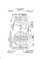
- Figure 1 is a side elevation of one form of a variable speed gear according to the present invention, mounted upon a suitable frame.
- Fig. 2 is a top plan view thereof.
- Fig. 3 is an enlarged top plan view, partly in section, of the drum of the eXpansion pulleys.
- Fig. 4 shows one of the end plates used in connection with my improved variable speed gear.
- Fig. 5 shows an intermediate spoke retaining plate.
- Fig. 6 is a view of one of the ball bearings used in connection with my improved variable speed gear.
- Fig. 7 is a plan View of one of the middle plates.
- Fig. 8 is a side view of the same.
- Fig. 9 is a section along line II-II of Fig. 7.
- Fig. 10 is a side elevation of one of the cam disks for operating the spokes.
- Fig. 11 is a section along line IIT-III of Fig. 10.
- Fig. 12 is a side view, partly in section, of one of the spokes centrally broken away, showing part of the rim member of one of said spokes.
- Fig. 13 is a similar view of another spo-ke.
- Fig. 14 is a side view of two of the spokes when connected, one of which being broken away.
- Fig. 15 is an enlarged front View of a cam-pate or guideelement used in conjunction with each of the spokes whereby the same may radially move by the cam disks.
- Fig. 16 is a side view thereof.
- FIG. 17 is an enlarged fragmentary end view, partly in section, of t-he means adapted to vary the diameters of the pulleys.
- Fig. 18 is a view, part-ly in section, taken on the line IT-H of Fig. 17.
- 19 is a side elevation, partly in section, of the manually operative wheel for adjusting the various parts of our variable speed gear.
- Fig. 20 is an end View of the operating wheel, partly in section and partly broken away.
- Fig. 21 is a fragmentary top plan view of the means fo-r taking up the slack of the belt, and
- Fig. 22 is an end view thereof, partly in section.
- the variable speed gear 10 may be mounted upon a frame, as 11, of any preferred form and which is pro-vided with side bars 12 and 13. Approximately centrally of the side bars 12 and 13 is provided a cross guide 14 formed ot' two parallel arranged Lshaped bars 1l"L and 1:?. or by lengthwise slotting a single har. as 1.3, lfig- 22, the opposite ends of each of which a re connected to said side bars, and in alinement with the cross-bars Het aud 15 is provided upon the side-bar 12 al projecting ⁇ bracket 16. rThe bracket 16 has an arm il' in the top face of which is formed a .slot or groove 1S, Figs.
- a head 19 and 207 and upon the end of said arm is provided a head 19 having a bearing therein.
- Journaled in the bearing ot the head 19 is one end oit' an ope 'ating shaft 20 which is also journaled in the side-bar 127 from which said shaft is disposed trans ⁇ .i'ersely ot the lramc 11 between the l.shapcd bars 111 and 15 of the guide 111 and has the end thereof journaled in the side-bar 13.
- er portion of the shaft 2O between the side-bar 12 and head 12 ot the bracket 1G is preferably channel-threaded7 as 21, and the opposed parts thereof between and adjacent to the sidebars 12 and 13 is provided peripherally with lf-shaped threads. as and 22u.
- a short stud 22" upon which is rotatably held one end of a vertically-disposed link or movable bracket, as 22C, and in the side-bar 12 oil the frame 11 is another short stud and a similar movable bracket.
- a vertically disposed stationary bracket 22 and a similar stationary bracket, not shownA7 is provided upon the sidebar 12 of the 'frame 11.
- each ot the movable vertical links 22C is jonrnaled a short shaft 2?-3 and 2l adapted to be driven by the power from the main source of motive supply, and in the free end of each of the stationary vertical brackets 22d is journaled short shafts 25 and 2G from which the desired ratio of speed from the gear is transmitted to the main driving shaft oit' the machinery to be operated.
- each of the shafts 23 and 25 is a passage, as 2(3 and 27, respectively7 and one end ot each of the shafts 2l and 2G is recessed, as at 2S and ln the recess 28 ot the shaft 2a is rotatably held one end of an inner shaft 8O which is also directed through the passage 2G ol' the shaft 2?) and the opposite end ot' said inner shaft is journaled in the head 31 ot a bracket 32 projecting laterally u pon the movable bracket 22.
- Each of the drums 3G and 37 of the eX- pansion pulleys 8S and 39 of our fariable speed gear is disposed between and revolubly operated by the shafts 23, 24 and 25, 26 respectively.
- To one end o'f each o'f the shafts 2B and 25 is held a circular end plate l() and to the opposed end of each of the shafts 2-t and 2G is held a circular end-plate l1.
- the end-plates at() and Lt1 are alike in form ⁇ each having a central opening 11% @ne face of each of said end-plates is recesse/d7 as at 41h by providing a concentric flange lf2 at the peripheral edge thereof, and projecting from the edge of each plate are a number of apertnred lugs, as L13, which are spaced apart at intervals.
- vlidway between the end-plates 110 and 41 are abutting middle plates -141 and
- the middle plates 4&1 and 45 are circular in form and of a similar size to the endplates l() and 41, each having a central opening LG and provided with a like number of apertured lugs. as 117, projecting at spaced intervals upon its peripheral edge.
- one face of each of the middle plates 44- and 415 has two spaced apart pa allel arranged guides or grooves t8 and 19 directed across each of said plates from one peripheral edge to the opposite peripheral edge thereof.
- rl ⁇ he guides or grooves 48 and l?) are formed between two parallel arranged flanges 50 and 51 disposed across the face at the central opening all of the plate and two similar flanges 52 and disposed across said face at the opposite diameter ol the opening 16.
- the opposed ends of each of the flanges 50 and 52 ten .inmate with a short curved wall, as 511 and formed integral therewith.
- a semi-circular wall 5G having its ends forming a juncture with the ends of the flange and diametrically opposite to the wall 56 is provided a similar semicircular wall which has its ends forming ⁇ a juncture with the ends of the flange
- the semi-circular walls 56 and 5T as well as the short curved walls 5l and 55 extend for a greater distance from the 'face of the plate Vthan the flanges of the guides @18 and l), thereby providing a recess 58 above said flanges which embraces the entire space between all o'f said walls.
- each of the middle plates le and fl-5 is provided with spaced apart parallel arranged guides or grooves and G() formed respectively between flanges G1, (l2 and G3, (El, which are disposed crosswise, as indicated ⁇ v with respect to the parallel flanges on the opposed fac-e of the plate and are directed across each of said plates from one peripheral edge to the opposite peripheral edo'e thereof.
- G1 flanges G1
- El which are disposed crosswise, as indicated ⁇ v with respect to the parallel flanges on the opposed fac-e of the plate and are directed across each of said plates from one peripheral edge to the opposite peripheral edo'e thereof.
- G5 At one of the ends of the lflanges G2 and is a short curved wall, as G5, and at the opposed ends of said flanges is a similar short wall, not shown.
- a semicircular wall 66 having its ends forming a juncture with the ends of the flange 61 and diametrically opposite to the wall 66 is provided a second semi-circular wall 67 the ends of which form a juncture with the ends of the flange G4.
- a second semi-circular wall 67 the ends of which form a juncture with the ends of the flange G4.
- intermediate plates G8, G9, 70 and 71 are circular in form and similar in diameter to the end plates and middle plates as above described.
- Each of the intermediate plates G8, (39, 70 and 71 has a central opening 72, Fig. 5, and at regular intervals upon the peripheral edge of each of said plates are formed apertured projecting lugs 73.
- Adjacent to one edge of the central opening 72 is provided upon one face of each of the intermediate plates a guide or groove 74 formed between two spaced apart parallel arranged flanges 75 and 7G which extend entirely across the plate and adjacent to the opposite edge of the central opening on the same face of the plate is a corresponding ⁇ guide or groove 77 formed between spaced apart parallel arranged flanges 78 and 79 also extending entirely across the plate.
- the ends of the flanges 76 and 7S are connected by curved walls 8O and S1, and at the peripheral edge of the plate is provided between the ends of the flange 75 a semicircular wall 82, while a similar semi-circular wall S3 is formed at the opposite peripheral edge of said plate between the ends of the flange 79.
- an annular flange S4, Fig. 3 is formed at the edge thereof, and by which a recess is provided.
- each of the cam disks 8S are substantially S-shaped and there are preferably7 eight of said disks employed in each of the drums 36 and 37 of the pulleys 3S and 39.
- Frein one face of each of the adjusting devices or cam disks SS is a projecting boss 89 having an opening 90 therethrough.
- each of the S-shaped disks 88 Upon the same face of each of the S-shaped disks 88 are formed spacedapart project-ing flanges, as 91, 92 and 93, 94, between which are provided cam grooves 95 and 96 which extend substantially the entire length of each of the curved arms thereof.
- Each of the disks 88 are rigidly keyed upon the shafts 30 and 33 of the pulleys 38 and 39, and one of said disks is positioned to rotate with said shafts in the recessed faces of each of the end plates 40, 41, each of the middle plates 44, 45 and each of the intermediate plates 68, 69, 70, 71.
- the central openings of the end plates, middle plates and intermediate plates are of a diameter so as to be loosely held upon the boss S9 of its associate cam disk 8S and by this arrangement said plates, will remain stationary when the cam disks are rotated by the shafts 30 and 33.
- each of the expansion pulleys 38 and 39 there ar-e eight of the segmental rims 87 each consisting of two of the spokes 86, and thus there are sixteen spokes in each pulley.
- Each of the spokes 86 has a substantially rectangular arm 9S adapted to be guided in the grooves 48, 49 and 59, 60 and 74, 77 of the middle-plates 44 and 45 and the intermediate plates 03, 69, 70, 71, respectively.
- a head-plate or rim member 99 of substantially the form of a parallelogram, Fig. 2, which is curved in the shape of an arc, as shown longitudinally in side view Figs. 1, 12, 13, and is also curved transversely, as indicated in Fig. 14.
- the spokes 86 and likewise the head-plates 99 are adapted to be arranged in pairs and connected by bolts, or otherwise, passing through openings in projecting flanges 100, and 101, Fig. 14, provided upon the corresponding transverse side of the head-plate of each pair of said spokes.
- one end of each of the segmental rims 8T is V-shaped, as 102, and at the opposite end thereof is a V- shaped notch 103"l so that all of the segmental rims will interlit to provide a proper bearing surface for the belt 103 which is trained over the pulleys 3S and 39 whether said pulleys are expanded or contracted.
- each pair of the spokes 86 are disposed in parallel relation.
- four pairs of the spokes S6 are spaced apart at varying distances and the other four pairs of the spokes thereof are correspondingly spaced apart.
- Adjacent to the free end of the arm 9S of each spoke S6 is provided al lug or guiding element 104 having cam-shaped edges and one of the cam edges is recessed as at 105 in which is seated a buffer or resilient pad 106.
- a cam disk S8 is keyed upon the inner shaft 30 oi' 8B and is seated in the recessed face 41 of the end plates -1-0, and in the cam grooves 95 and 96 of the said disk are seated the lugs or guiding elements 101i ⁇ of two of the spokes SG.
- the intermediate plate 68 is passed over the inner shaft 30 or 33 and another of the cam disks 88 is keyed upon the inner shaft after the boss S9 of said cam disk is directed through the opening 72 of said intermediate plate.
- the second cam disk SS is positioned in the recess S5 of the plate GS and the arms 9S of the two spo-kes 8f3 will be held so as to be moved in opposite directions in -the guiding grooves Til and 7T of said intermediate plate. ln each of the cam grooves 95 and 9G of the second cam disk S8 is litted the lugs or guiding elements 101 of two other spokes 86.
- the intermediate plate 69 is then passed over the inner shaft 30 or 33 and a third cam disk 88 is keyed upon the inner shaft after the boss S9 of the disk is directed through the opening 'T2 of the plate (if).
- the third cam disk S8 Will be seated in the recess 85 of the plate 69 and the arms 9S of the third pair of spokes S6 vfill be disposed in the guiding; grooves el-S and 4st) of the middle plate t4 aud adapted also to be moved therein in opposite directions when said middle plate is passed over the inner shaft and is followed by the fourth cani disk S8 being keyed upon said inner shaft subsequent to passing the boss Si) thereof through the opening L16 of the middle plate.
- the cam grooves 95 and 96 of the fourth cam disk 88 is positioned the lugs or guiding element 1011 of two more of the spokes 8G, the fourth cam disk being* seated in the recessed face 6G of the middle plate dit.
- each of the drums 8G and 37 are formed and the other half thereof is similarly arranged, but the order is reversed in the arrangement of the middle plate 115, the intermediate plates and 71 ⁇ r the end plate -ll and the other four cam disks SB, as Well as the eight other spokes 86.
- the drums 3G and 37 are assembled a plurality of tie rods, as 10S, which are directed through corresponding apertured lugs 113 of the end plates l-O and l1, the apertured lugs T3 of the intermediate plates (38, titl TO, 71, and the apertured lugs 11:7 of the middle plates 1111-, and 45, and the parts are held firmly together by nuts 109 and 110 screwed upon the opposed threaded ends of each of said tie rods.
- tal rims 87 of each of the pulleys 38 and 39 are then formed by connecting the projecting flanges 100 and 101 of the head-plates 99 with bolts, as above described, and in this manner the spokes 86 of two of the segmental rims Will be adjusted in opposite directions by the cam disks S8 seated in the end plates L LO and 41.
- the spokes S6 of two other segmental rims 87 Will be adjusted in opposite directions by the cam disks seated in the intermediate plates G8 and 71, and the spokes S6 of two more of the segmental rims will be adjusted in opposite directions by the cam disks seated in the intermediate plates 69 and 70 While the spokes SG of the last.
- the inner shafts 3() and 33 therefore serve as operating' means for the cam disks 88 and are adapted to rotate independently of the short shafts 23 and 2li, 25 and 26, which rotate When the pulleys 38 and 39 are revolved.
- a nut 11G which is provided interiorly thereof with channelthreads so as to be adjusted upon said shaft when rotated.
- the nut 116 may be square or rectangular in shape and upon one of its faces is a boss 117 having a threaded recess therein for reception of the thread end of a lug or pin 11S which is guided in the slot or groove 1S of the arm 17 of the bracket 1G.
- a similar boss 119 in which is screwed a bolt 120.
- boss 117 between the head of the lun' 11S and the nut 116 is pivotally held substantially the central part of an adjusting lever or rod 121., and on the boss 119 between the head of the bolt 120 and the nut 11G is pivoted likewise substantially the central part of a second adjusting lever or rod 122.
- lever 121 is pivotally connected to a link 123 which is pivoted to a bracket 124e provided upon the side-bar 12 of the frame 11 adjacent to the forward part the lever 122 is pivotally Iconnected to a link 125 which is pivoted to a bracket 126 also provided upon the side bar 12 of the frame 11 adjacent to the rear part of the shaft of the pulley 39.
- the opposite end of each of the levers 121 and 122 is bifurcated or has a yoke, as 127 and 128, which have curved arms 129, 130 and 131, 132, respectively, and through the ends of all of said arms is formed an opening 133, Figs.
- each of the sleeves 137 and 137a is peripherally grooved, as 138, and within said groove is arranged the inner collar 136.
- a raceway 139 and 140 is provided between the opposed peripheral edges of the inner collar 136 and the walls of the groove 138 of each of the sleeves 137 and 137a in each of which are revolubly held a plurality of antifriction balls 141.
- each of the sleeves 137 and 137a is a tooth 142 and diametrically opposite thereto is a second tooth 143 also formed upon the interior surface of said sleeves.
- the teeth 142 and 143 are guided in the spiral grooves 144 provided in the exterior surface of jackets 145 and 145a one of which is rigidly held upon each of the inner shafts 30 and 33 and arranged between the side bar 12 and the head 31 of the bracket 32.
- the inner shafts 30 and 33 will be simultaneously rotated in opposite directions when the jackets 145 and 145a are revolved by the movement of the teeth 142 and 143 of the sleeve 137 in the groove 144 of said jacket for the purpose which will hereinafter be more fully explained.
- each of the nuts 152 and 153 Projecting upwardly from the top surface of each of the nuts 152 and 153 are two obliquely disposed lugs 154, 154 and 155, 1551.
- the opposed end of each of the lugs 154, 154a and 155, 155a are spaced apart and in said space is held the respective ends of the adjusting arms 148 and 149 so that when the operating shaft 20 is rotated the nuts 152 and 153 will move transversely upon said shaft and in turn the said adjusting arms will be gripped by the lugs 154, 154a and 155, 155EL to move said arms longitudinally whereby the vertical links 22c will be shifted to throw the pulley38 in an outwardly direction with respect to the pulley 39, thus taking up all slack or sag of the belt 103.
- a manually operative controlling means or wheel 156 Figs. 1, 2, 19, 20 The wheel 156'is Vkeyed upon the shaft 20 above the arm 17 of the bracket 16 and adjacent to the cross-bar 12.
- the peripheral edge of the wheel 156 is grooved, as 157, and in said groove is provided a plurality of teeth 158 adapted to grip a chain or cable 159 which is trained in the groove over said wheel.
- the levers or rods 121 and 122 will thereby be shifted for moving at the same time the guiding sleeves 137 and 137, so that the teeth 142 and 143 thereof will be guided in the spiral grooves 144 for rotating the jackets 145 and 14592 Simultaneously with the rotation of the jackets 145 and 1458* the inner shafts 30 and 33 of the drums 36 and 37 will be revolved in the same directions and the cam disks 88 which are keyed thereupon will accordingly be rotated.
- the cam disks 88 By arranging the cam disks 88 so that the spokes 86 of one of the pulleys will be expanded and the spokes 86 in the other pulley contracted, as shown in F ig.
- the rotation of the cam disks 88 will cause the cam-shaped lugs 104 of the spokes 86 to be so guided in the cam grooves 95 and 96 as to move radially all the arms 98 of said spokes in the groovesl 74 and 77 of the intermediate plates 68, 69, 70, 71 and in the grooves 48, 49 and 59 60 of the middle plates 44 and 45.
- the diameter of one of the pulleys will thereby be expanded and simultaneously therewith the diameter of the other pulley will be decreased as the movement of the parts thereof are operated in a similar manner but reversely, and when the wheel 156 is revolved any sag of the belt 103 is taken up, as above described, by shifting the pulley 38 wit-h adjustment of the arms 148 and 149 when the operating shaft 20 is rotated.
- a variable speed gear in combination a frame having two side bars; two expansion pulleys each arranged between the ends of the side bars and each having a drum; two rims, each provided upon one o-f the pulleys, and each consisting of a plurality of interiitting segments and each segment being formed of two curved parallelogram plates; means adapted to connect said plates; a plurality of pairs of spokes, each spoke having one of the ends thereof formed upon one surface of one of the curved plates; a guiding element provided at the opposite end of each of the spokes; two tubular shafts and two recessed shafts, one of the tubular shafts and one of the recessed shafts being journaled in alinement at the opposite ends of the side bars of said frame; an antifriction bearing provided in the recess of each of the recessed shafts and in each of the tubular shafts; two inner shafts, each having one end rotatably held in the antifriction bearing of one of the recessed shafts and the other end rotatable
- cam grooves therein for reception of the guiding elements of the spokes whereby said spokes may be adjusted to alternately expand and contract the segments of the rims ofthe pulleys simultaneously; an operating shaft journaled midway of the side bars of the frame; means provided upon the ope ating shaft and adaptedwhen operated to simultaneously rotate the inner shafts for moving the adjusting devices to guide the guiding elements of the spokes in the cam groove; and manually operative means provided upon the operating shaft and adapted to operate the means for rotating said inner shaft.
- variable speed gear in combination; a frame having two side bars; two expansion pulleys each arranged between the ends of the side bars and each having a drum; two interlitting segmental rims, each provided upon one of the pulleys; a plurality of pairs of spokes, each spoke having one of the ends thereof formed upon one surface of one of the segments of the rims;
- a variable speed gear in combination; a frame having two side bars; two expansion pulleys each arranged between the ends of the side bars and each having a drum; two interfitting segmental rims, each provided upon one of the pulleys; a plurality of pairs of spokes, each spoke having one end thereof formed upon one surface of one of the segments of the rims; a guiding element provided at the opposite end of each of the spokes; two tubular shafts and two recessed shafts, one of the tubular shafts and one of the recessed shafts being journaled in alinement at the opposite ends of the side bars of said frame; an anti-friction bearing provided in the recess of each of the recessed shafts and in one end of each of the tubular shafts; two inner shafts, each having one end rotatably held in the anti-friction bearing of one of the recessed shafts and the other end rotatable in the anti-friction bearing of the corresponding alined tubular shaft; end plates forming the faces
- a variable speed gear in combination; a frame having two side bars; two exshafts and two recessed shafts, one of the tubular shafts and one of the recessed shafts being journaled in alinement at the opposite ends of the side bars of said frame; an antifriction bearing provided in the recess of each of the recessed shafts and in one end of each of the tubular shafts; two inner shaftsA ⁇ each having one end rotatably held in the anti-friction bearing ⁇ of one of the recessed shafts and the other end rotatable in the anti-friction bearing of the corresponding alined tubular shaft; end-plates forming the faces of both drums and arranged upon the opposed vends of each of said alined tubular shafts and recessed shafts; a plurality of adjusting devices keyed at intervals upon each of the inner shafts between the endplates of the drums and provided with means adapted to guide the guiding elements of the spokes whereby said spokes may be adjusted to alternately expand and
- a variable speed gear in combination; a frame having two side bars; two expansion pulleys each arranged between the ends of the side bars and each having a drum; two rims, each provided upon one of the pulleys, and each consisting of a plurality of interlitting segments; each segment being formed of two curved parallelogram plates; means adapted to connect said plates; a plurality of pairs of spokes7 each spoke having one end thereof formed upon one surface of one of the curved plates; a plurality of guiding elements, each provided at the opposite end of one of the spokes; two tubular shafts and two recessed shafts, one of the tubular shafts and one of the recessed shafts being journaled in alinement at the opposite ends ⁇ of the side bars of said franie; an anti-friction bearing provided in the recess of each of the recessed shafts and in one end of each of the tubular shafts; two inner shafts; each having one end rotatably held in the anti-friction bearing of one of the recessed
- adjusting devices keyed at inter "als upon each of the inner shafts between the end-plates of the drums and having oppositely disposed cam grooves therein for reception of the guiding elements of the spokes whereby said spokes may be adjusted to alternately expand and contract the segments of the rims of the pulleys sin'rultaneously; a projecting boss provided upon one face of each of the cani adjusting ⁇ devices; a plate loosely held upon the projecting boss of each of the adjusting devices and provided upon one of its faces with means adapted to guide the spokes dining adjustment thereof by said adjusting devices; an ojfierating shaft journaled midway of the side bars of the frame; means provided upon the operating shaft and adapted when operated to sinuiltaneously rotate. the inner shafts for moving the. adjusting devices to guide the guiding' elements of the spokes in the cani grooves therein: and manually operative means provided upon the operating shaft and adapted to operate the means for rotating said inner shaft.
- variable speed gear in combination; a frame having two side bars; two cxpansion pulleys each arranged between the ends of the side bars and each having a drum; two curved segmental rims, one of which is provided upon each of the expansion pulleys and each segment of which has a substzintially rl-shaped end and a substantially V-shaped notch provided at the opposite end thereof; a plurality of pairs of spokes; each spoke having one end thereof formed upon one surface of oneof the curved segments; a plurality of guiding elements. each provided at the opposite end of one of the spokes; two tubular shafts and two recessed shafts; one of the tubular shafts and one.
- each of said alined tubular shafts and recessed shafts a plurality of substantially S-shaped cani disks; each having a boss projecting from one face thereof said disks being keyed at intervals upon each of the inner shafts between the end-plates of the drums and having oppositely disposed curved cam grooves therein for reception of the guiding elements of the spokes whereby said spokes inay be adjusted to alternately expand and contract the segments of the rims of the pulleys simultaneously; an operating shaft jourhaled midway of the side bars of the frame; a plate loosely held upon the projecting boss of each of the S-shaped cam disks and provi ded upon one of its faces with two paraHel-arranged guides adapted to guide the spoke during adj ustinent thereof by said S-shaped cani disks; means provided upon the operating shaft and adapted when operated to siinultanernisly rotate the inner shafts for moving the i5-shaped cain disks to guide the guiding elements of the spokes in the
- ay variable speed gear In ay variable speed gear; .in combination; a frame having two side bars; two expansion pulleys each arranged between the ends of the side bars and each having a drinn; two curved segmental rims7 one of which is provided upon each of the pulleys and each segment of which has a substantially 'lf-shaped end and a substantially V- shaped notch provided at the opposite end thereof; a plurality of pairs of spokes; each spoke ha ving one end thereof formed upon one surface of one of the curved segments; a plurality of guiding elements; each provided at the opposite end of one of the spokes; two tubular shafts and two recessed shafts; one of the tubular shafts and one of the recessed shafts being journaled in alinement at the opposite ends of the side bars of said frame; an anti-friction bearing provided in the recess of each of the recessed shafts and in one end of each of the tubular shafts; two inner shafts, each having one end rotatably held in
- a variable speed gear in combination; a frame having two side bars; two eX- pansion pulleys each arranged between t-he ends of the side bars and each having a drum; two curved segmental rims, each provided upon one of the expansion pulleys and each segment of which has a substantially V- shaped end and a substantially V-shaped notch provided at the oppo-site end thereof; a plurality of pairs of spokes, each spoke having one end thereof formed upon one surface of one of the curved segments and the spo-kes of each pair being disposed in spaced-apart parallel arrangement; a plurality of guiding elements, each provided at the opposite end of one of the spokes; two tubular shafts and two recessed shafts, one of the tubular shafts and one of the recessed shafts being jo-urnaled in alinement at the opposite ends of the side bars of said frame; an anti-friction bearing provided in the recess of each of the recessed shafts and in one end of each of the tubular shafts and
- a variable speed gear in combination; a frame having two side bars; two expansion pulleys each arranged between the ends of the side bars and each having a drum; two rims, each provided upon one of the pulleys, and each consisting of a plurality of interfitting segments, formed of two curved parallelogram plates; means adapted to connect said plates; a plurality of spokes, each spoke having one end formed upon one surface of one of the curved plates; a plurality of guiding elements, each provided at the opposite end of one of the spokes; two tubular shafts and two recessed shafts, one of the tubular shafts and one of the recessed shafts being journaled in alinement at the opposite ends of the side bars of said frame; an anti-friction bearing, provided in the recess of each of the recessed shafts and in the one end of each of the tubular shafts; two inner shafts, each having one end rotatably held in the antifriction bearing of one of the recessed shafts and the other end
- a variable speed gear in combination; a fraine having two side bars; two eX- pansion pulleys each arranged between the ends of the side bars and each having a druin; two interfitting segmental riins, each provided upon one of the pulleys; a plurality of pairs of spokes, each spoke having one end thereof forined upon one surface of one of the segn'ients of the riin; a plurality of guiding elements; each provided at the opposite end of one of the spokes; two tubus lar shafts and two recessed shafts, one of the tubular shafts and one of the recessed shafts being ournaled in alineinent at the opposite ends of the side bars of said frame; an antifriction bearing provided in the recess of each of the recessed shafts and in one end of each of the tubular shafts; two inner shafts; each having one end rotatably held in the anti-friction bearing of one of the recessed shafts and the other end rot
- variable speed gear in combination; a fraine having two side bars; two eX- pansion pulleys each arranged between the ends of the side bars and each having a drinn; two riins7 each provided upon one of the pulleys and each consisting of a plurality of intertitting segments forined of two curved iriarallelograin plates having corresponding projecting flanges connected by bolts; a 1plurality of spokes, each spoke hav ing one end formed upon one surface of one of the curved plat-es; a plurality of lugs, each provided at the opposite end of one of the spokes; two tubular shafts and two recessed shafts7 one of the tubular shafts and one of the recessed sl afts being journaled in alinenient at the opposite ends of the side bars of said franie; an anti-fricti on bearing provided in the recess of each of the recessed shafts and in one end of each of the
- variable speed gear in combinaM tion; a frame having two side bars; two et'- pansion pulleys each arranged between the ends of the side bars and each having a druin; two rinis7 each provided.
- a variable speed gear in combination; a frame having two side bars; two expansion pulleys each arranged between the ends of the side bars and each having a drum; two rims, each provided upon one of the pulleys; and each consisting of a plurality of interfitting segments, formed of two curved parallelogram plates having corresponding projecting flanges connected by bolts; a plurality of spokes; each spoke having one end formed upon one surface of one of the curved plates; a plurality of recessed lugs; each provided at the opposite end of one of the spokes; a plurality of buers; each movably held within the recess of the lug; a plurality of springs, each seated in said recess and normally serving to force the buffer outwardly; two tubular shafts and two recessed shafts, one of the tubular shafts and one of the recessed shafts being journaled in alinement at the opposite ends of the side bars of said frame; an anti-friction bearing provided in the recess of
- a variable speed gear in combination; a frame having two side bars; two eX- pansion pulleys each arranged between the ends of the side bars and each having a drum; two rims, each provided upon one of the pulleys and each consisting of a plurality of interiitting segments formed o-f two curved parallelogram plates having corresponding projecting flanges connecte-d by bolts; a plurality of spokes; each spoke having one end formed upon one surface of one of the curved plates; a plurality of cams, each having a recess in one edge thereof and formed upon the opposite end of one of the spokes; a plurality of buffers, each inovably held in the recess of the cam; a spring seated in each recess and normally serving to force the buffer outwardly; two tubular shafts and two recessed shafts; one
- 1G. ln a variable speed gear; in combination; a frame having two side bars; two expansion pulleys each arranged between the ends of the side bars and each having a drum; two interfitting segmental rims, each provided upon one of the pulleys; a plurality of pairs of spokes, cach having one end thereof formed upon one surface of one of the segments of the rims; a plurality of cams, each having a recess in one of its edges and formed upon the opposite end of one of the spokes; a plurality of buffers, each movably held in the recess of the cam; a spring seated in each recess and normally serving to force the buffer outwardly; two tubular shafts and two recessed shafts, one of the tubular shafts and one of the recessed shafts being journaled in alinement at the opposite ends of the side bars of said frame; an anti-friction bearing provided in the recess of each of the recessed shafts and in one end of each of the tubular shafts;
- an operating shaft journaled midway of the side bars of the frame; means provided upon the operating shaft and adapted when operated to simultaneously rotate the inner shafts for moving the adjusting devices to guide the recessed cams and the buffers of the spokes in the cam grooves of said adjusting devices; and manually operative means provided upon the operating shaft and adapted to operate the means for rotating said inner shaft.
- a variable speed gear in combination; a. frame having two side bars; two eX- pansion pulleys each arranged between the ends of the side bars and each having a drum; two interiitting segmental rims, each provided upon one of the pulleys; a plurality of pairs of spokes, each spoke having one end formed upon one surface of one of the segments of the rims; a plurality of cams, each provided at the opposite end of one of the spokes and having al recess therein; a plurality of buffers, each movably held in the recess of the cam; a spring seated in eachrecess and normally serving to force the buffer outwardly; two tubular shafts and two recessed shafts, one of the tubular shafts and one of the recessed shafts being journaled in alinement at the opposite ends of the side bars of said frame; an antifriction bearing provided in the recess of each of the recessed shafts and in one end of each of the tubular shafts; two inner shafts
- 1S. 1n a variable speed gear; in combi-- nation; a frame having two side bars; two expansion pulleys each arranged between the cnds of the side bars and each having a drum; two curved segmental rims, each provided upon one of the pulleys and each segment of which has a substantially lf'- shaped end and a substantially V-shaped notch provided at the opposite end thereof; a plurality of pairs of spokes, each spoke having one end formed upon one surface of one of the curved segments; a plurality of cams, each provided at the opposite end of one of the spokes and having a recess therein; a plurality of buffers, each movably held in the recess of the cam; a spring s eated in each recess and normally serving to force the buffer outwardly; two tubular shafts and two recessed shafts, one of the tubular shafts and one of the recessed shafts ⁇ being journaled in alinement at the opposite ends of the side bars of said frame; an
- a frame having two side bars; two expansion pulleys each arranged between the ends of t-he side bars and each having a drum; two curved segmental rims; each provided upon one of the pulleys and each segment of which has a substantially il-shaped end and a substantially V-shaped notch provided at the opposite end thereof; a plurality of pairs of spokes, each spoke having one end formed upon one surface of one of the curved segments; a plurality of cams, each provided at the opposite end of one of the spokes and having a recess in one edge thereof; a plurality of buffers, each movably held in the recess of a cam; a spring seated in each recess and normally serving to force the buifer outwardly; two tubular shafts and two recessed shafts, one of the tubular shafts and one of the recessed shafts being journaled4 in alinement at the opposite ends of the side bars of said frame; an anti-friction bearing provided in the recess of each of the a
- variable speed gear in combination; a frame having two side bars; a movable vertical bracket provided upon 19.
- a variable speed gear in combieach of the side bars at one end thereof;
- two expansion pulleys each arranged between the ends of the side bars; two interliftingl segmental rims, each provided upon one of the pulleys; a plurality of pairsl of spokes, each spoke having ⁇ one end thereof formed upon one surface of one of the segments of the rims; a plurality of guiding elements7 each provided at the opposite end of one of the spokes; two tubular shafts and two recessed shafts, one of the tubular shafts and one of the recessed shafts being journaled in the movable brackets of the side bars of the frame; an anti-friction bearing; provided in the recess of each of the recessed shafts and in one end of each of the tubular shafts; two innerl shafts, each having one end rotatably held in the anti-friction bearing of one of the recessed shafts and the other end rotatable in the anti-friction bearing of the correspendingl alined tubular shaft; two drums,izivinr end-plates arranged upon the opposed ends
- variable speed gear in combination; a frame having,l two side bars; a vertically movable bracket provided upon each of the side bars at one eiicl,thereof; a stationary bracket provided upon each of the side bars at the opposite end thereof;
- two expansion pulleys each arranged between the ends of the side bars; two interlitting segmental rims, each provided upon one of the pulleys; a plurality of pairs of spokes, each spoke having one end thereof formed upon one surface of one of the segments of the rims; a plurality of pguiding elements, each provided at the opposite end of one of the spokes; a tubular shaft and a recessed shaft journaled in alinement at the opposite ends of the movable Vertical brackets of the side bars of said frame; a tubular shaft and a recessed shaft journaled in alinei'nent at the ends of the stationary brackets of the side bars of the frame; an antifriction bearing' provided in the recess of each of the recessed shafts and in one end of each of the tubular shafts; two inner shafts, each havingv one end rotatably held in the anti-friction bear-infr of one of the recessed shafts and the other end rotatable in the anti-friction bearing' in
- variable speed gear in combination; a fra-me having two side bars; a movable vertical bracket provided upon each of the side bars at one end thereof; a stationary bracket provided upon each of the side bars at the opposite end thereof; two interitting segmental rims, each provided upo-n one of the pulleys; a plurality of pairs of spokes, each spoke having one end formed upon one surface of one of the segments of the rims; a plurality of guiding cams, each provided at the opposite end of one of the spokes; a tubular shaft and a recessed shaft, being journaled in alinement at the opposite ends of the movable vertical bracketof the side bars of said fra-me; a tubular shaftand a recessed shaft, each having one end journaled in alinement at the ends of the stationary brackets of the side bars of said frame; an anti-friction bearing provided in the recess of each of the recessed shafts and in one end of each of the tubular shafts; two inner shafts, each
- cent-ral cam shaped disks and each of said circular middle plates having two parallel arranged grooves communicating with said recesses of the plates and having two parallel arranged grooves provided upon the opposite face thereof and disposed transversely with respect to the grooves of the recessed face thereof, all the grooves of said circular middle plates and intermediate plates being adapted to receive the spokes of the segmental rim so as to be adjusted when the guiding cams of the spokes are engaged by the S-shaped disks; means adapted to connect the peripheral edges of the end plates, the intermediate plate and the middle plates; an operating shaft journaled midway of the side bars of the frame means provided-upon l the operating shaft and adapted when operated to simultaneously rotate the inner shafts for moving the S-shaped disks to guide the guiding cams of the spokes in the cam grooves of said S-shaped disks; and manually operative means provided upon the operating sliaft and adapted to operate the means for rotating said inner shaft.
- a variable speed gear in combination; a frame having two side bars; a vertically disposed movable bracketprovided upon each of the side bars at one end thereof; a stationary bracketprovided upon each of the side bars at the opposite end thereof; two expansion pulleys each arranged between the ends of the side bars; two curved segmental rims, each provided upon one of the pulleys and each segment of which has a substantially V-shaped end and a substantially il-shaped notch provided at the opposite end thereof; a plurality of pairs of spokes, each spoke having one end thereof formed upon one surface of one of the curved segments; a plurality of guiding cams, each provided at the opposite end of one of the spokes; a tubular shaft and a recessed shaft, each having one end journaled in alinement at the opposite ends of the vertically disposed-movable brackets of the side bars of said frame; a tubular shaft and a recessed shaft, being journaled in alinement at the ends of the stationary brackets of the'side bars
Description
W. & W. A. CHURCH-SMITH.
VARIABLE SPEED GEAR. APPLICATION FILED 00T. 20.1910.
Patented Aug. 5, 1913.
5 SHEETS-SHEET 1.
cnLuMsM PLANonRAPl-i co.. wAsmNG-roN. D. c.
W. L W. A. CHURCH-SMITH.
VARIABLE SPEED GEAR. APPLIUATION FILED 00T. 20, 1910.
Patented Aug. 5, 1913.
5 SHEETS-SHEET 2.
'wich QR) tbm/cose@ -W. & W. A. CHURCH-SMITH.
VARIABLE SPEED GEAR.
o0. 1 0u 1 v0, uw u A d Lw n G Lb na D.. nw l 9 1 0, 2 1 NV 0 D E L I nr. N o I T G I L P P A I n( 2 2 o. 9 n0 0 1 5 SHEETS-SHBET 3.
.KIN
cuLuMBlA PLANOGRAPH Co,. wAsrxNG-ruN, D. c.
W. & WA. CHURCH-SMITH.
^ VARIABLE SPEED GEAR.v
APPLIUATION FILED 0012.20, 1910.
Patented Aug. 5, 1913.
5 SHEETS-SHEET 4.
W. & W. A. CHURCH-SMITH.
VARIABLE SPEED GEAR.
APPLICATION HLED 00120, 1910.
Patented Allg. 5, 1913.
5 SHEETS-SHEET 5.
wa wm www @www lu-.. A $2 Alid WQ ...Q Q NN@ \m\ mm\ T .NQ N. MN
.Y WW1/Lewes I m c. ML.
UNITED STATES PATENT OFFICE.
WILLIAM CHURCH-SMITH AND WILLIAM A. CHURCH-SMITH, OF VVHITESTONE, NEW
YORK.
VARIABLE-SPEED GEAR.
Specification of Letters Patent.
Patented Aug. 5,1913.
To all whom t may concern Be it known that we, VILLIAM CHURCH- SMITH and ViLLLiM A. CHURCH-SMITH, both citizens of the United States, and residents of Vhitestone, county of Queens, and State of New York, have invented certain new and novel Improvements in Variable- Speed Gears, of which the following is a full` clear, and exact specification.
This invention relates to a class of devices or form of mechanism adapted for use in conjunction with the operation of machinery whereby the highestl efficiency may be obtained therefrom.
Our invention has for its primary objectto provide a variable speed gear of durable and effective construction by which the power from the main source of motive supply may be transmitted at any desired ratio of speed to the operating shaft from which may be driven a plurality of machines; to provide a variable speed gear requiring a minimum amount of power for its operaticn and with littl'e or no waste thereof; to provide a form of the gear adapted to transmit any amount of power; and to provide a gear which may be conveniently mounted on girders, ceilings, walls or floors of buildings as occasion may require. TWe attain these objects by providing two expansion pulleys which are carried by the same frame and are rotated at the same time by one belt. Each of the pulleys may bc expanded to twice its diameter, and are altered in eX- pansion and contraction simultaneously thereby producing the required variation of speed.
Further objects of our invention are to provide forms of expansion pulleys each having a rim consisting of a plurality of intersecting segments which are formed by two connected corresponding spokes each provided with a head-plate o-r a rim member; to provide a. plurality of retaining plates as a means to guide the expansion and contraction of the spokes; to provide a plurality of adjust-ing devices or means adapted to move the spokes simultaneously to expanded or contracted positions; to provide means for operating the adjusting devices whereby the diameter of one of the pulleys will be increased and the diameter of the other pulley decreased simultaneously therewith; and to pro-vide means adapted to take up any slack or sag of the belt trained over the pulleys.
lVit-h these and other objects in view, the invention will be hereinafter more particularly described with reference to the accompanying drawings which form a part of this specification and will then be pointed out in the appended claims.
In the drawing, Figure 1 is a side elevation of one form of a variable speed gear according to the present invention, mounted upon a suitable frame. Fig. 2 is a top plan view thereof. Fig. 3 is an enlarged top plan view, partly in section, of the drum of the eXpansion pulleys. Fig. 4 shows one of the end plates used in connection with my improved variable speed gear. Fig. 5 shows an intermediate spoke retaining plate. Fig. 6 is a view of one of the ball bearings used in connection with my improved variable speed gear. Fig. 7 is a plan View of one of the middle plates. Fig. 8 is a side view of the same. Fig. 9 is a section along line II-II of Fig. 7. Fig. 10 is a side elevation of one of the cam disks for operating the spokes. Fig. 11 is a section along line IIT-III of Fig. 10. Fig. 12 is a side view, partly in section, of one of the spokes centrally broken away, showing part of the rim member of one of said spokes. Fig. 13 is a similar view of another spo-ke. Fig. 14 is a side view of two of the spokes when connected, one of which being broken away. Fig. 15 is an enlarged front View of a cam-pate or guideelement used in conjunction with each of the spokes whereby the same may radially move by the cam disks. Fig. 16 is a side view thereof. Fig. 17 is an enlarged fragmentary end view, partly in section, of t-he means adapted to vary the diameters of the pulleys. Fig. 18 is a view, part-ly in section, taken on the line IT-H of Fig. 17. 19 is a side elevation, partly in section, of the manually operative wheel for adjusting the various parts of our variable speed gear. Fig. 20 is an end View of the operating wheel, partly in section and partly broken away. Fig. 21 is a fragmentary top plan view of the means fo-r taking up the slack of the belt, and Fig. 22 is an end view thereof, partly in section.
The variable speed gear 10 may be mounted upon a frame, as 11, of any preferred form and which is pro-vided with side bars 12 and 13. Approximately centrally of the side bars 12 and 13 is provided a cross guide 14 formed ot' two parallel arranged Lshaped bars 1l"L and 1:?. or by lengthwise slotting a single har. as 1.3, lfig- 22, the opposite ends of each of which a re connected to said side bars, and in alinement with the cross-bars Het aud 15 is provided upon the side-bar 12 al projecting` bracket 16. rThe bracket 16 has an arm il' in the top face of which is formed a .slot or groove 1S, Figs. 19 and 207 and upon the end of said arm is provided a head 19 having a bearing therein. Journaled in the bearing ot the head 19 is one end oit' an ope 'ating shaft 20 which is also journaled in the side-bar 127 from which said shaft is disposed trans\.i'ersely ot the lramc 11 between the l.shapcd bars 111 and 15 of the guide 111 and has the end thereof journaled in the side-bar 13. er portion of the shaft 2O between the side-bar 12 and head 12 ot the bracket 1G is preferably channel-threaded7 as 21, and the opposed parts thereof between and adjacent to the sidebars 12 and 13 is provided peripherally with lf-shaped threads. as and 22u.
In one part of the side-bar 13 of the trame 11v a short stud 22" upon which is rotatably held one end of a vertically-disposed link or movable bracket, as 22C, and in the side-bar 12 oil the frame 11 is another short stud and a similar movable bracket. Upon the opposite part of the side-bar 1B arranged a vertically disposed stationary bracket 22 and a similar stationary bracket, not shownA7 is provided upon the sidebar 12 of the 'frame 11. ln the opposite end of each ot the movable vertical links 22C is jonrnaled a short shaft 2?-3 and 2l adapted to be driven by the power from the main source of motive supply, and in the free end of each of the stationary vertical brackets 22d is journaled short shafts 25 and 2G from which the desired ratio of speed from the gear is transmitted to the main driving shaft oit' the machinery to be operated. Through each of the shafts 23 and 25 is a passage, as 2(3 and 27, respectively7 and one end ot each of the shafts 2l and 2G is recessed, as at 2S and ln the recess 28 ot the shaft 2a is rotatably held one end of an inner shaft 8O which is also directed through the passage 2G ol' the shaft 2?) and the opposite end ot' said inner shaft is journaled in the head 31 ot a bracket 32 projecting laterally u pon the movable bracket 22. Likewise in the recess 29 of the shaft 2G is rotatably held one end of an inner shaft 3B which directed through the passage 2 of the shaft 25 and the opposite end of said inner' shaft is journaled in the head 3l off bracket 22d projecting laterallyT from the side-bar 12 of the frame 11.
Each of the drums 3G and 37 of the eX- pansion pulleys 8S and 39 of our fariable speed gear is disposed between and revolubly operated by the shafts 23, 24 and 25, 26 respectively. To one end o'f each o'f the shafts 2B and 25 is held a circular end plate l() and to the opposed end of each of the shafts 2-t and 2G is held a circular end-plate l1. The end-plates at() and Lt1 are alike in form` each having a central opening 11% @ne face of each of said end-plates is recesse/d7 as at 41h by providing a concentric flange lf2 at the peripheral edge thereof, and projecting from the edge of each plate are a number of apertnred lugs, as L13, which are spaced apart at intervals. vlidway between the end-plates 110 and 41 are abutting middle plates -141 and The middle plates 4&1 and 45 are circular in form and of a similar size to the endplates l() and 41, each having a central opening LG and provided with a like number of apertured lugs. as 117, projecting at spaced intervals upon its peripheral edge. As illus trated in Figs. 7, 8, t), one face of each of the middle plates 44- and 415 has two spaced apart pa allel arranged guides or grooves t8 and 19 directed across each of said plates from one peripheral edge to the opposite peripheral edge thereof. rl`he guides or grooves 48 and l?) are formed between two parallel arranged flanges 50 and 51 disposed across the face at the central opening all of the plate and two similar flanges 52 and disposed across said face at the opposite diameter ol the opening 16. The opposed ends of each of the flanges 50 and 52 ten .inmate with a short curved wall, as 511 and formed integral therewith. At one peripheral edge oli the same tace of said plate is provided a semi-circular wall 5G having its ends forming a juncture with the ends of the flange and diametrically opposite to the wall 56 is provided a similar semicircular wall which has its ends forming` a juncture with the ends of the flange The semi-circular walls 56 and 5T as well as the short curved walls 5l and 55 extend for a greater distance from the 'face of the plate Vthan the flanges of the guides @18 and l), thereby providing a recess 58 above said flanges which embraces the entire space between all o'f said walls. The opposite face of each of the middle plates le and fl-5 is provided with spaced apart parallel arranged guides or grooves and G() formed respectively between flanges G1, (l2 and G3, (El, which are disposed crosswise, as indicated`v with respect to the parallel flanges on the opposed fac-e of the plate and are directed across each of said plates from one peripheral edge to the opposite peripheral edo'e thereof. At one of the ends of the lflanges G2 and is a short curved wall, as G5, and at the opposed ends of said flanges is a similar short wall, not shown. Also at one peripheral edge of the same face of each of the middle plates is provided a semicircular wall 66 having its ends forming a juncture with the ends of the flange 61 and diametrically opposite to the wall 66 is provided a second semi-circular wall 67 the ends of which form a juncture with the ends of the flange G4. Between the end plate 40 and the middle plate 44 are arranged two contacting intermediate plates 68 and G9, and between the end-plate 41 and the middle plate 45 are arranged two contacting intermediate plates 70 and 71.
rl`he intermediate plates G8, G9, 70 and 71 are circular in form and similar in diameter to the end plates and middle plates as above described. Each of the intermediate plates G8, (39, 70 and 71 has a central opening 72, Fig. 5, and at regular intervals upon the peripheral edge of each of said plates are formed apertured projecting lugs 73. Adjacent to one edge of the central opening 72 is provided upon one face of each of the intermediate plates a guide or groove 74 formed between two spaced apart parallel arranged flanges 75 and 7G which extend entirely across the plate and adjacent to the opposite edge of the central opening on the same face of the plate is a corresponding` guide or groove 77 formed between spaced apart parallel arranged flanges 78 and 79 also extending entirely across the plate. The ends of the flanges 76 and 7S are connected by curved walls 8O and S1, and at the peripheral edge of the plate is provided between the ends of the flange 75 a semicircular wall 82, while a similar semi-circular wall S3 is formed at the opposite peripheral edge of said plate between the ends of the flange 79. Upon the opposite face of each of the intermediate plates GS. G9, 70 and 'T1 is an annular flange S4, Fig. 3, at the edge thereof, and by which a recess is provided. rlhe intermediate plates 68, G9, 70 and T1 in conjunction with the middle plates 44 and serve as a means to movably retain vand guide the movement of spokes S0 of the segmental rims ST of the pulleys 3S and of our variable speed gear as will be hereinafter more fully described.
As a means adapted to move the spokes S6 simultaneously for moving the segmental rims ST to expanded or contracted positions we provide a plurality of adjusting devices or cam disks SS. Figs. 3, 10 and 11. As indicated in Fig. 10, each of the cam disks 8S are substantially S-shaped and there are preferably7 eight of said disks employed in each of the drums 36 and 37 of the pulleys 3S and 39. Frein one face of each of the adjusting devices or cam disks SS is a projecting boss 89 having an opening 90 therethrough. Upon the same face of each of the S-shaped disks 88 are formed spacedapart project-ing flanges, as 91, 92 and 93, 94, between which are provided cam grooves 95 and 96 which extend substantially the entire length of each of the curved arms thereof. Each of the disks 88 are rigidly keyed upon the shafts 30 and 33 of the pulleys 38 and 39, and one of said disks is positioned to rotate with said shafts in the recessed faces of each of the end plates 40, 41, each of the middle plates 44, 45 and each of the intermediate plates 68, 69, 70, 71. The central openings of the end plates, middle plates and intermediate plates are of a diameter so as to be loosely held upon the boss S9 of its associate cam disk 8S and by this arrangement said plates, will remain stationary when the cam disks are rotated by the shafts 30 and 33.
in each of the expansion pulleys 38 and 39 there ar-e eight of the segmental rims 87 each consisting of two of the spokes 86, and thus there are sixteen spokes in each pulley. Each of the spokes 86 has a substantially rectangular arm 9S adapted to be guided in the grooves 48, 49 and 59, 60 and 74, 77 of the middle-plates 44 and 45 and the intermediate plates 03, 69, 70, 71, respectively. Upon one end of each of the arms 9S is a head-plate or rim member 99 of substantially the form of a parallelogram, Fig. 2, which is curved in the shape of an arc, as shown longitudinally in side view Figs. 1, 12, 13, and is also curved transversely, as indicated in Fig. 14. The spokes 86 and likewise the head-plates 99 are adapted to be arranged in pairs and connected by bolts, or otherwise, passing through openings in projecting flanges 100, and 101, Fig. 14, provided upon the corresponding transverse side of the head-plate of each pair of said spokes. By this manner of arranging each pair of the hea d-plates 99 one end of each of the segmental rims 8T is V-shaped, as 102, and at the opposite end thereof is a V- shaped notch 103"l so that all of the segmental rims will interlit to provide a proper bearing surface for the belt 103 which is trained over the pulleys 3S and 39 whether said pulleys are expanded or contracted. The arms 9S of each pair of the spokes 86 are disposed in parallel relation. In the formation of the segmental rims S7 of each of the expansible pulleys, 38, 39, four pairs of the spokes S6 are spaced apart at varying distances and the other four pairs of the spokes thereof are correspondingly spaced apart. Adjacent to the free end of the arm 9S of each spoke S6 is provided al lug or guiding element 104 having cam-shaped edges and one of the cam edges is recessed as at 105 in which is seated a buffer or resilient pad 106. (lne end of the buffer 106 is recessed and in said recess is a coil spring, as 107, which tends normally to press the buffer 106 from its seat within the recess 105 of the guiding element 104. The camshaped element 104 is adapted to be guided in the cam grooves and 96 of the S- shaped arms of the disks or adjusting' devices 88.
1n assei'nbling` the drum 3G or 37 a cam disk S8 is keyed upon the inner shaft 30 oi' 8B and is seated in the recessed face 41 of the end plates -1-0, and in the cam grooves 95 and 96 of the said disk are seated the lugs or guiding elements 101i` of two of the spokes SG. The intermediate plate 68 is passed over the inner shaft 30 or 33 and another of the cam disks 88 is keyed upon the inner shaft after the boss S9 of said cam disk is directed through the opening 72 of said intermediate plate. fly this arrangement the second cam disk SS is positioned in the recess S5 of the plate GS and the arms 9S of the two spo-kes 8f3 will be held so as to be moved in opposite directions in -the guiding grooves Til and 7T of said intermediate plate. ln each of the cam grooves 95 and 9G of the second cam disk S8 is litted the lugs or guiding elements 101 of two other spokes 86. The intermediate plate 69 is then passed over the inner shaft 30 or 33 and a third cam disk 88 is keyed upon the inner shaft after the boss S9 of the disk is directed through the opening 'T2 of the plate (if). The third cam disk S8 Will be seated in the recess 85 of the plate 69 and the arms 9S of the third pair of spokes S6 vfill be disposed in the guiding; grooves el-S and 4st) of the middle plate t4 aud adapted also to be moved therein in opposite directions when said middle plate is passed over the inner shaft and is followed by the fourth cani disk S8 being keyed upon said inner shaft subsequent to passing the boss Si) thereof through the opening L16 of the middle plate. In each of the cam grooves 95 and 96 of the fourth cam disk 88 is positioned the lugs or guiding element 1011 of two more of the spokes 8G, the fourth cam disk being* seated in the recessed face 6G of the middle plate dit. Thus, as described, one-half of each of the drums 8G and 37 are formed and the other half thereof is similarly arranged, but the order is reversed in the arrangement of the middle plate 115, the intermediate plates and 71`r the end plate -ll and the other four cam disks SB, as Well as the eight other spokes 86. Then the drums 3G and 37 are assembled a plurality of tie rods, as 10S, which are directed through corresponding apertured lugs 113 of the end plates l-O and l1, the apertured lugs T3 of the intermediate plates (38, titl TO, 71, and the apertured lugs 11:7 of the middle plates 1111-, and 45, and the parts are held firmly together by nuts 109 and 110 screwed upon the opposed threaded ends of each of said tie rods. The segmen: tal rims 87 of each of the pulleys 38 and 39 are then formed by connecting the projecting flanges 100 and 101 of the head-plates 99 with bolts, as above described, and in this manner the spokes 86 of two of the segmental rims Will be adjusted in opposite directions by the cam disks S8 seated in the end plates L LO and 41. The spokes S6 of two other segmental rims 87 Will be adjusted in opposite directions by the cam disks seated in the intermediate plates G8 and 71, and the spokes S6 of two more of the segmental rims will be adjusted in opposite directions by the cam disks seated in the intermediate plates 69 and 70 While the spokes SG of the last. two segmental rims of each pulley will be adjusted by the cam disks seated in the middle-plates ist and 15. The intermediate plates GS, G9, 70, 71 and the middle plates 4i, 45 are loosely held upon the bosses 89 ot the cam disks S8 and as the cam disks are rigidly held to the inner shafts 30 and 33 it is clear, that all the segmental spokes 8G will be sinmltaneously adjusted to expand or contract the segmental rims 87 of each pulley When the inner shafts are rotated. The inner shafts 3() and 33 therefore serve as operating' means for the cam disks 88 and are adapted to rotate independently of the short shafts 23 and 2li, 25 and 26, which rotate When the pulleys 38 and 39 are revolved. In order to allow for free rotation of the expansion pulleys 38 and 39 upon the inner shafts 8O and and in the re cesses 28 and 29 of the short shafts 2liand 26 is provided a ball bearing 111 and 112. and in the passages 26 and 27 of the short shafts 23 and 25 is arranged a ball bearing 113 and 114.
To rotate the inner shafts in opposite directions whereby the diameter of the rim of one of the pulleys in our variable speed gear will be increased and. the diameter of the rim of the other pulley Will be simultaneously decreased ive provide a form of means or adj listing levers 115. Upon the channel threaded portion of the shaft 20 is a nut 11G which is provided interiorly thereof with channelthreads so as to be adjusted upon said shaft when rotated. The nut 116 may be square or rectangular in shape and upon one of its faces is a boss 117 having a threaded recess therein for reception of the thread end of a lug or pin 11S which is guided in the slot or groove 1S of the arm 17 of the bracket 1G. Upon the opposite face of the nut 116 is a similar boss 119 in which is screwed a bolt 120. Upon the boss 117 between the head of the lun' 11S and the nut 116 is pivotally held substantially the central part of an adjusting lever or rod 121., and on the boss 119 between the head of the bolt 120 and the nut 11G is pivoted likewise substantially the central part of a second adjusting lever or rod 122. One end of the lever 121 is pivotally connected to a link 123 which is pivoted to a bracket 124e provided upon the side-bar 12 of the frame 11 adjacent to the forward part the lever 122 is pivotally Iconnected to a link 125 which is pivoted to a bracket 126 also provided upon the side bar 12 of the frame 11 adjacent to the rear part of the shaft of the pulley 39. The opposite end of each of the levers 121 and 122 is bifurcated or has a yoke, as 127 and 128, which have curved arms 129, 130 and 131, 132, respectively, and through the ends of all of said arms is formed an opening 133, Figs. 2 and 17, for reception of threaded pins 134 and 135 which may be screwed into openings provided diametrically opposite to each other in the exterior surface of an inner collar 136 of guiding sleeves 137 and 1373. The exterior surface of each of the sleeves 137 and 137a is peripherally grooved, as 138, and within said groove is arranged the inner collar 136. Between the opposed peripheral edges of the inner collar 136 and the walls of the groove 138 of each of the sleeves 137 and 137a is provided a raceway 139 and 140 in each of which are revolubly held a plurality of antifriction balls 141. At one edge of the interior surface of each of the sleeves 137 and 137a is a tooth 142 and diametrically opposite thereto is a second tooth 143 also formed upon the interior surface of said sleeves. The teeth 142 and 143 are guided in the spiral grooves 144 provided in the exterior surface of jackets 145 and 145a one of which is rigidly held upon each of the inner shafts 30 and 33 and arranged between the side bar 12 and the head 31 of the bracket 32. Thus the inner shafts 30 and 33 will be simultaneously rotated in opposite directions when the jackets 145 and 145a are revolved by the movement of the teeth 142 and 143 of the sleeve 137 in the groove 144 of said jacket for the purpose which will hereinafter be more fully explained.
1n order to take up any slack or sag of the belt 103 simultaneously with the adjustment of the diameters of the rims of the pulleys 38 and 39 upon the shafts 23 and 24 are loosely held sleeves 146 and 146a and exteriorly upon each of said sleeves are formed spaced apertured lugs 147 and 1472". Between each of the lugs 147 and 1473 is pivotally held one end of adjusting arms 148 and 149, each of said arms are guided between two pulleys 150, 150L and 151, 151a arranged adjacent to the guide 14. Upon the V-shaped threaded portions 22 and 22a of the operating shaft 20 is provided a nut- 152 and 153 adapted to be guided in the guide 14 between the L-shaped bars 14a and 15. Projecting upwardly from the top surface of each of the nuts 152 and 153 are two obliquely disposed lugs 154, 154 and 155, 1551. The opposed end of each of the lugs 154, 154a and 155, 155a are spaced apart and in said space is held the respective ends of the adjusting arms 148 and 149 so that when the operating shaft 20 is rotated the nuts 152 and 153 will move transversely upon said shaft and in turn the said adjusting arms will be gripped by the lugs 154, 154a and 155, 155EL to move said arms longitudinally whereby the vertical links 22c will be shifted to throw the pulley38 in an outwardly direction with respect to the pulley 39, thus taking up all slack or sag of the belt 103.
For the purpose of conveniently and readily operating the various parts of our variable speed gear to simultaneously expand or increase the diameters of the pulleys 38 and 39 we provide a manually operative controlling means or wheel 156 Figs. 1, 2, 19, 20. The wheel 156'is Vkeyed upon the shaft 20 above the arm 17 of the bracket 16 and adjacent to the cross-bar 12. The peripheral edge of the wheel 156 is grooved, as 157, and in said groove is provided a plurality of teeth 158 adapted to grip a chain or cable 159 which is trained in the groove over said wheel. By manually pulling one end of the chain 159 the wheel 156 and shaft 20 will be rotated and the nutI 116 will be directed laterally upon said shaft. The levers or rods 121 and 122 will thereby be shifted for moving at the same time the guiding sleeves 137 and 137, so that the teeth 142 and 143 thereof will be guided in the spiral grooves 144 for rotating the jackets 145 and 14592 Simultaneously with the rotation of the jackets 145 and 1458* the inner shafts 30 and 33 of the drums 36 and 37 will be revolved in the same directions and the cam disks 88 which are keyed thereupon will accordingly be rotated. By arranging the cam disks 88 so that the spokes 86 of one of the pulleys will be expanded and the spokes 86 in the other pulley contracted, as shown in F ig. 2, the rotation of the cam disks 88 will cause the cam-shaped lugs 104 of the spokes 86 to be so guided in the cam grooves 95 and 96 as to move radially all the arms 98 of said spokes in the groovesl 74 and 77 of the intermediate plates 68, 69, 70, 71 and in the grooves 48, 49 and 59 60 of the middle plates 44 and 45. The diameter of one of the pulleys will thereby be expanded and simultaneously therewith the diameter of the other pulley will be decreased as the movement of the parts thereof are operated in a similar manner but reversely, and when the wheel 156 is revolved any sag of the belt 103 is taken up, as above described, by shifting the pulley 38 wit-h adjustment of the arms 148 and 149 when the operating shaft 20 is rotated.
1n the foregoing description we have embodied the preferred form of our invention, but we do not wish tobe understood as limiting ourselves thereto, as we are aware that modifications may be made therein without departing from the principle or sacrificing any of the advantages of this invent-ion, therefore we reserve to ourselves the right to make such changes as fairly fall within the scope thereof.
Having thus described our invention, we claim as new and desire to secure by Letters Patent l. in a variable speed gear; in combination; a frame having two side bars; two eX- pansion pulleys each arranged between one of the ends of the side bars and each having a drum; two rims, each provided upon one of the pulleys, and each consisting of a plurality of intermitting segments, each of said segments being formed of two connected curved parallelogram plates provide-d upon one surface thereof with spaced part parallel arranged corresponding spokes having Vtheir inner ends movably held in the drums and adapted to be adjusted radially with respect to the circumference of the drums; two tubular shafts and two recessed shafts, one of the tubular shafts and one of the recessed shafts being journaled in alinement at the opposite ends of the side bars of said frame; two inner shafts, each havingl one end ro tatably held in one of the recessed shafts and the other end rotatable in the corresponding alined tubular shaft; four end-plates, forming the opposite faces of the drums and rigidly held to the opposite ends of said alined tubular shafts and recessed shafts; a plu rality of disks keyed at. intervals upon each of the inner shafts between the end-plates of the drums and having oppositely disposed cam grooves therein; means provided upon the end of each of the spokes and adapted to be guided in the cam grooves of the disks whereby said spokes may be adjusted to alternately expand and contract the segments of the rims of the pulleys simultaneously; an operating shaft journaled midway of the side bars of the frame; means provided upon the operating shaft and adapted when operated to simultaneously rotate the inner shafts for moving the disks to guide the adjusting means of the spokes in the cam grooves thereof; and manually operative means provided upon the operating shaft and adapted to operate the means for rotating said inner shaft.
2, In a variable speed gear in combination a frame having two side bars; two expansion pulleys each arranged between the ends of the side bars and each having a drum; two rims, each provided upon one o-f the pulleys, and each consisting of a plurality of interiitting segments and each segment being formed of two curved parallelogram plates; means adapted to connect said plates; a plurality of pairs of spokes, each spoke having one of the ends thereof formed upon one surface of one of the curved plates; a guiding element provided at the opposite end of each of the spokes; two tubular shafts and two recessed shafts, one of the tubular shafts and one of the recessed shafts being journaled in alinement at the opposite ends of the side bars of said frame; an antifriction bearing provided in the recess of each of the recessed shafts and in each of the tubular shafts; two inner shafts, each having one end rotatably held in the antifriction bearing of one of the recessed shafts and the other end rotatable in the anti# friction bearing of the corresponding alined tubular shaft; endv plates forming the faces of both drums and arranged upon the opposed ends of said alined tubular shafts and recessed shafts; a plurality of adjusting devices keyed at intervals upon each of the inner shafts between the end-plates of the drums and having oppositely disposed. cam grooves therein for reception of the guiding elements of the spokes whereby said spokes may be adjusted to alternately expand and contract the segments of the rims ofthe pulleys simultaneously; an operating shaft journaled midway of the side bars of the frame; means provided upon the ope ating shaft and adaptedwhen operated to simultaneously rotate the inner shafts for moving the adjusting devices to guide the guiding elements of the spokes in the cam groove; and manually operative means provided upon the operating shaft and adapted to operate the means for rotating said inner shaft.
3. ln a variable speed gear; in combination; a frame having two side bars; two expansion pulleys each arranged between the ends of the side bars and each having a drum; two interlitting segmental rims, each provided upon one of the pulleys; a plurality of pairs of spokes, each spoke having one of the ends thereof formed upon one surface of one of the segments of the rims;
la plurality of guiding elements, each provided at the opposite end of one of the i spokes; two tubular shafts and two recessed shafts, one of the tubular shafts and one of 4 the recessed shafts being journaled in alinement at the opposite ends of the side bars of said frame; an anti-friction bearing provided in the recess of each of the recessed shafts and in one end of each of the tubular shafts; two inner shafts, each having one end rotatably held in the anti-friction bearing of one of the recessed shafts and the other end rotatable in the anti-frictionbearing of the corresponding alined tubular multaneously; a plurality of intermediate plates movably held to the cam disks and adapted to guide the spokes during adjustment thereof by the cam groo-ves of said cam disks; an operating shaft journaled midway of the side bars of the frame; means provided upon the operating shaft and adapted when operated to simultaneously rotate the inner shafts for moving the cam disks to guide the guiding elements of the spokes in the curved cam grooves; and manually oper` ative means provided upon the operating shaft and adapted to operate the means for rotating said inner shaft.
4. In a variable speed gear; in combination; a frame having two side bars; two expansion pulleys each arranged between the ends of the side bars and each having a drum; two interfitting segmental rims, each provided upon one of the pulleys; a plurality of pairs of spokes, each spoke having one end thereof formed upon one surface of one of the segments of the rims; a guiding element provided at the opposite end of each of the spokes; two tubular shafts and two recessed shafts, one of the tubular shafts and one of the recessed shafts being journaled in alinement at the opposite ends of the side bars of said frame; an anti-friction bearing provided in the recess of each of the recessed shafts and in one end of each of the tubular shafts; two inner shafts, each having one end rotatably held in the anti-friction bearing of one of the recessed shafts and the other end rotatable in the anti-friction bearing of the corresponding alined tubular shaft; end plates forming the faces of both drums and arranged upon the opposed ends of each of said alined tubular shafts and recessed shafts; a plurality of cam disks, each having a boss projecting from o-ne end face thereof said disk being keyed at intervals upon each of the inner shafts between the end-plates of the drums; each of said cam disks having two oppositely-disposed guides provided in one face thereof and adapted to adjust the guiding elements of the spokes to alternately expand and contract the segments of the rims of the pulleys simultaneously; a plurality of intermediate plates, each loosely held upon the projecting boss of one of the cani disks and adapted to guide the spokes during adjustment thereof by said cam disks; an operating shaft j ournaled midway of the side bars of the frame; means provided upon the operating shaft and adapted when operated to simultaneously rotate the inner shafts for moving the cam disks to guide the guiding elements of the spokes in the guides therein; and manually operative means provided upon the operating shaft and adapted to operate the means for rotating said inner shaft.
5. In a variable speed gear; in combination; a frame having two side bars; two exshafts and two recessed shafts, one of the tubular shafts and one of the recessed shafts being journaled in alinement at the opposite ends of the side bars of said frame; an antifriction bearing provided in the recess of each of the recessed shafts and in one end of each of the tubular shafts; two inner shaftsA` each having one end rotatably held in the anti-friction bearing` of one of the recessed shafts and the other end rotatable in the anti-friction bearing of the corresponding alined tubular shaft; end-plates forming the faces of both drums and arranged upon the opposed vends of each of said alined tubular shafts and recessed shafts; a plurality of adjusting devices keyed at intervals upon each of the inner shafts between the endplates of the drums and provided with means adapted to guide the guiding elements of the spokes whereby said spokes may be adjusted to alternately expand and contract the segments of the rims o-f the pulleys simultaneously; a plurality of intermediate plates movably held to the cam disks each of said intermediate plates being provided upon one of its faces with means adapted to guide the spokes during adjustment thereof by said adjusting devices; an operating shaft journaled midway of the side bars of the frame; means provided upon the operating shaft and adapted when operated to simultaneously rotate the inner shafts for moving the adjusting devices to guide the guiding elements of the spokes in the guiding means thereof; and manually operative means provided upon the operating shaft and adapted to operate the means for rotating said inner shaft.
6. In a variable speed gear; in combination; a frame having two side bars; two expansion pulleys each arranged between the ends of the side bars and each having a drum; two rims, each provided upon one of the pulleys, and each consisting of a plurality of interlitting segments; each segment being formed of two curved parallelogram plates; means adapted to connect said plates; a plurality of pairs of spokes7 each spoke having one end thereof formed upon one surface of one of the curved plates; a plurality of guiding elements, each provided at the opposite end of one of the spokes; two tubular shafts and two recessed shafts, one of the tubular shafts and one of the recessed shafts being journaled in alinement at the opposite ends` of the side bars of said franie; an anti-friction bearing provided in the recess of each of the recessed shafts and in one end of each of the tubular shafts; two inner shafts; each having one end rotatably held in the anti-friction bearing of one of the recessed shafts and the other end rotatable in the anti-friction bearing of the corresponding alined tubular shaft; end plates forming the faces of both drums and arranged upon the opposite ends of each of said alined tubular shafts and recessed shafts; a. plurality of adjusting devices keyed at inter "als upon each of the inner shafts between the end-plates of the drums and having oppositely disposed cam grooves therein for reception of the guiding elements of the spokes whereby said spokes may be adjusted to alternately expand and contract the segments of the rims of the pulleys sin'rultaneously; a projecting boss provided upon one face of each of the cani adjusting` devices; a plate loosely held upon the projecting boss of each of the adjusting devices and provided upon one of its faces with means adapted to guide the spokes dining adjustment thereof by said adjusting devices; an ojfierating shaft journaled midway of the side bars of the frame; means provided upon the operating shaft and adapted when operated to sinuiltaneously rotate. the inner shafts for moving the. adjusting devices to guide the guiding' elements of the spokes in the cani grooves therein: and manually operative means provided upon the operating shaft and adapted to operate the means for rotating said inner shaft.
7. ln a variable speed gear; in combination; a frame having two side bars; two cxpansion pulleys each arranged between the ends of the side bars and each having a drum; two curved segmental rims, one of which is provided upon each of the expansion pulleys and each segment of which has a substzintially rl-shaped end and a substantially V-shaped notch provided at the opposite end thereof; a plurality of pairs of spokes; each spoke having one end thereof formed upon one surface of oneof the curved segments; a plurality of guiding elements. each provided at the opposite end of one of the spokes; two tubular shafts and two recessed shafts; one of the tubular shafts and one. of the recessed shafts being journalcd in alinement at the opposite ends of the side bars of said frame; an anti-friction bearing provided in the recess of each of the recessed shafts and in one end of each of the tubular shafts; two inner shafts`r each having one end rotatably held in the anti-friction bearing of one of the rece. sed shafts and the other end rotatable in the antifriction bearing of the correspoinling alined tubular shaft; end plates fm'niing the faces of both drums and arranged upon` the oppoineens? site ends of each of said alined tubular shafts and recessed shafts; a plurality of substantially S-shaped cani disks; each having a boss projecting from one face thereof said disks being keyed at intervals upon each of the inner shafts between the end-plates of the drums and having oppositely disposed curved cam grooves therein for reception of the guiding elements of the spokes whereby said spokes inay be adjusted to alternately expand and contract the segments of the rims of the pulleys simultaneously; an operating shaft jourhaled midway of the side bars of the frame; a plate loosely held upon the projecting boss of each of the S-shaped cam disks and provi ded upon one of its faces with two paraHel-arranged guides adapted to guide the spoke during adj ustinent thereof by said S-shaped cani disks; means provided upon the operating shaft and adapted when operated to siinultanernisly rotate the inner shafts for moving the i5-shaped cain disks to guide the guiding elements of the spokes in the curved earn grooves; and manually operative means provided upon the operating shaft and adapted to operate the means for rotating said inner shaft.
tl. In ay variable speed gear; .in combination; a frame having two side bars; two expansion pulleys each arranged between the ends of the side bars and each having a drinn; two curved segmental rims7 one of which is provided upon each of the pulleys and each segment of which has a substantially 'lf-shaped end and a substantially V- shaped notch provided at the opposite end thereof; a plurality of pairs of spokes; each spoke ha ving one end thereof formed upon one surface of one of the curved segments; a plurality of guiding elements; each provided at the opposite end of one of the spokes; two tubular shafts and two recessed shafts; one of the tubular shafts and one of the recessed shafts being journaled in alinement at the opposite ends of the side bars of said frame; an anti-friction bearing provided in the recess of each of the recessed shafts and in one end of each of the tubular shafts; two inner shafts, each having one end rotatably held in the anti-friction bearing of one of the recessed shafts and the other end rotatable in the anti-friction bearing in the corresponding alined tubular shaft; end plates forming the faces of both drums and arranged upon the opposed ends of each of said alined tubular shafts and recessed shafts; a plurality of cani disks, each having a boss projecting from one face thereof, said disks being keyed at intervals upon each of thix in nier shafts between the endplates of the drums and each of said cam disks having two oppositely disposed curved guides provided in one face thereof and adapted to adjust the guiding elements of the spokes to alternately expand and contract the segments of the rims of the pulleys simultaneously; a plate loosely held upon the proj ecting` boss of each of the cam disks and provided uponone of its faces with two parallel arranged guides adapted to guide the spokes during adjustment thereof by said cam disks; an operating shaft o-urnaled midway of the side bars of the frame; means provided upon the operating shaft and adapted when operated to simultaneously rotate the inner shafts for moving the cam disks to guide the guiding element of the spokes in the curved guides; and manually operative means provided upon the operating shaft and adapted to operate the means for rot-ating said inner shaft.
9. In a variable speed gear; in combination; a frame having two side bars; two eX- pansion pulleys each arranged between t-he ends of the side bars and each having a drum; two curved segmental rims, each provided upon one of the expansion pulleys and each segment of which has a substantially V- shaped end and a substantially V-shaped notch provided at the oppo-site end thereof; a plurality of pairs of spokes, each spoke having one end thereof formed upon one surface of one of the curved segments and the spo-kes of each pair being disposed in spaced-apart parallel arrangement; a plurality of guiding elements, each provided at the opposite end of one of the spokes; two tubular shafts and two recessed shafts, one of the tubular shafts and one of the recessed shafts being jo-urnaled in alinement at the opposite ends of the side bars of said frame; an anti-friction bearing provided in the recess of each of the recessed shafts and in one end of each of the tubular shafts; two inner shafts, each having one end rotatably held in the anti-friction bearing of one of the recessed shafts and the other end rotatable in the anti-friction bearing of the corresponding alined tubular shaft; end-plates forming the faces of both drums and arranged upon the opposed ends of each of said alined 'tubular shafts and recessed shafts; a plural` ity of disks, each having a boss projecting from one face thereof said disks being keyed at intervals upon each of the inner shafts between the end-plates of the drums and each of said disks having a substantially S- shaped groove therein for the reception of the guiding elements of the spokes whereby said spokes may be adjusted to alternately expand and contract the segments o-f the rims of the pulleys simultaneously; a plurality of intermediate plates and middle plates arranged between the disks and loosely held upon the respective projecting bosses thereof, each of said plates being provided with two parallel-arranged guides upon one of its faces for guiding the spo-kes during adjustment thereof by said disks; an operating shaft journaled midway of the side bars of the frame; means provided upon the operating shaft and adapted when o-perated to simultaneously rotate the inner shafts for moving the disks to guide the guiding elements of the spokes in the S-shaped grooves; and manually operative means provided upon the operating shaft and adapted to operate the means for rotating said inner shaft.
l0. In a variable speed gear; in combination; a frame having two side bars; two expansion pulleys each arranged between the ends of the side bars and each having a drum; two rims, each provided upon one of the pulleys, and each consisting of a plurality of interfitting segments, formed of two curved parallelogram plates; means adapted to connect said plates; a plurality of spokes, each spoke having one end formed upon one surface of one of the curved plates; a plurality of guiding elements, each provided at the opposite end of one of the spokes; two tubular shafts and two recessed shafts, one of the tubular shafts and one of the recessed shafts being journaled in alinement at the opposite ends of the side bars of said frame; an anti-friction bearing, provided in the recess of each of the recessed shafts and in the one end of each of the tubular shafts; two inner shafts, each having one end rotatably held in the antifriction bearing of one of the recessed shafts and the other end rotatable in the anti-friction bearing of the corresponding alined tubular shaft; end plates forming the faces of both drums and arranged upon the opposed ends of each of said alined tubular shafts and recessed shafts; a plurality of disks each having a boss projecting from one face thereof said disks being keyed at intervals upon each of the inner shafts between the end-plates of the drums and each of said disks having a substantially S- shaped groove therein for reception of the guiding elements of the spokes whereby said spokes may be adjusted to alternately expand and contract the segments of the rims of the pulleys simultaneously; a plurality of intermediate plates and middle plates arranged between the disks and loosely held upon the respective projecting boss thereof, each of said plates being provided with two parallel arranged guides upon one of its faces for guiding the spokes during adjustment thereof by said disks; an operating shaft journaled midway of the side bars of the frame; means provided upon the operating shaft and adapted when operated to simultaneously rotate the inner shafts for moving the disks to guide the guiding elements of the spokes in the S-shaped grooves; and manually operative means provided upon the operating shaft and adapted to operate the means for rotating said inner shaft.
l1. In a variable speed gear; in combination; a fraine having two side bars; two eX- pansion pulleys each arranged between the ends of the side bars and each having a druin; two interfitting segmental riins, each provided upon one of the pulleys; a plurality of pairs of spokes, each spoke having one end thereof forined upon one surface of one of the segn'ients of the riin; a plurality of guiding elements; each provided at the opposite end of one of the spokes; two tubus lar shafts and two recessed shafts, one of the tubular shafts and one of the recessed shafts being ournaled in alineinent at the opposite ends of the side bars of said frame; an antifriction bearing provided in the recess of each of the recessed shafts and in one end of each of the tubular shafts; two inner shafts; each having one end rotatably held in the anti-friction bearing of one of the recessed shafts and the other end rotatable in the anti-friction bearing of the correspending alined tubular shaft; end plates forming the faces of both drums and arranged upon the opposed ends of each of said alined tubular shafts and recessed shafts; a plurality of substantially S- shaped cani disks each having a boss projecting frein one face thereof said disks being keyed at intervals upon each of the inner shafts between the endsplates of the druins and having oppositely-disposed curved cain grooves therein for reception of the guiding elements of the spokes whereby said spokes inay be adjusted to alternately expand and contract the segments of the riins of the pulleys simultaneously; a plurality of inter- `mediate plates and middle plates arranged between the f-shaped cani disks and loosely held upon the respective projecting bosses thereof each of said plates being providedwith two parallel arranged guides upon one of its faces for guiding the spokes during adjustment thereof by said S-shaped disks; an operating shaft journaled inidway of the side bars of the frame; ineans provided upon the operating shaft and adapted when operated to simultaneously rotate the inner shafts for moving the shaped disks to guide the guiding cleinents of the spokes in the curved, Cain grooves; and inanually operative means provided upon the operating shaft and adapted to operate the nieans for rotating said inner shaft.
12. ln a variable speed gear; in combination; a fraine having two side bars; two eX- pansion pulleys each arranged between the ends of the side bars and each having a drinn; two riins7 each provided upon one of the pulleys and each consisting of a plurality of intertitting segments forined of two curved iriarallelograin plates having corresponding projecting flanges connected by bolts; a 1plurality of spokes, each spoke hav ing one end formed upon one surface of one of the curved plat-es; a plurality of lugs, each provided at the opposite end of one of the spokes; two tubular shafts and two recessed shafts7 one of the tubular shafts and one of the recessed sl afts being journaled in alinenient at the opposite ends of the side bars of said franie; an anti-fricti on bearing provided in the recess of each of the recessed shafts and in one end of each of the tubular shafts; two inner shafts, each. having one end rotatably held in the anti-friction bearing of one of the recessed shafts and the other end rotatable in the anti-friction bearing7 of the corresponding alined tubular shaft; end plates forming the faces of both drums and arranged upon the opposed ends of each of said alined tubular shafts and recessed shafts; a plurality of substantially S-shaped disks7 each having a boss projecting froin one face thereof said disks being keyed at intervals upon each of the inner' shafts between the end-plates of the drums and having oppositely disposed curved cain grooves for reception of the lugs of the spokes whereby said spokes may be adjusted to alternately expand and contract the seginents of the rinis of the pulleys siinultzu neously; an operating shaft journal-ed inidway of the side bars of the freine; nieans provided upon the operating shaft and adapted when operated to simultaneously rotate the inner shafts for inoving the adjusting devices to guide the lugs of the spokes in the curved cani grooves, and inanually operative means provided upon the operating shaft and adapted to operate the ineans for rotating said inner shaft.
13. ln a variable speed gear; in combinaM tion; a frame having two side bars; two et'- pansion pulleys each arranged between the ends of the side bars and each having a druin; two rinis7 each provided. upon one of the pulleys and each consistingl of aplurality of intertitting segnients formed of two curved parallelograin plates having corresponding projecting tlai s connected by bolts; a plurality of spokW7 each spoke having' one end forined upon one surface of one of the curved plates; a plurality of recessed lugs, each provided at the opposite end of one of the spokes; a plurality of buffers each held in the recess of one of the lugs; two tulnilar shafts and two recessed shafts, one of the tubular shafts and one of the recessed shafts l* alinenient at the opposite ends of the side bars of said fi-aire; an anti-friction bearing provided in the recess of each of the recessed shafts and in one end of each of the tubular shafts; two inner shafts, each having one end rotatably held in the antifriction bearing of one of the recessed shafts and the other end rotatable in the anti-friction bearing of the Corresponding` alined tubular shaft; end plates forming the faces eing journaled in llt) of both drums and arranged upon the opposed ends of each of said alined tubular shafts and recessed shafts; a plurality of substantially S-shaped disks; each having a boss projecting from one face thereof said disks being` keyed at intervals upon each of the inner shafts between the end-plates of the drums and having oppositely disposed cam grooves therein for reception of the lugs and buifers of the spokes whereby said spokes may be adjusted to alternately expand and contract the segments of the rims of the pulleys simultaneously; an operating shaft journaled midway of the side bars of the frame; guiding means arranged between each of the S-shaped disks and adapte-d to coperate with the cam grooves thereof to guide the spokes during adjustment by said S-shaped disks; means provided upon the operating shaft and adapted when operated to simultaneously rotate the inner shafts for moving the S-shaped disks to guide the recessed lugs and buers of the spokes in the cam grooves of said S-shaped disks; and manually operative means provided upon the operating shaft and adapted to operate the means for. rotating said inner shaft.
le. In a variable speed gear; in combination; a frame having two side bars; two expansion pulleys each arranged between the ends of the side bars and each having a drum; two rims, each provided upon one of the pulleys; and each consisting of a plurality of interfitting segments, formed of two curved parallelogram plates having corresponding projecting flanges connected by bolts; a plurality of spokes; each spoke having one end formed upon one surface of one of the curved plates; a plurality of recessed lugs; each provided at the opposite end of one of the spokes; a plurality of buers; each movably held within the recess of the lug; a plurality of springs, each seated in said recess and normally serving to force the buffer outwardly; two tubular shafts and two recessed shafts, one of the tubular shafts and one of the recessed shafts being journaled in alinement at the opposite ends of the side bars of said frame; an anti-friction bearing provided in the recess of each of the recessed shafts and in one end of each of the tubular shafts; two inner shafts, each having one end rotatably held in the anti-friction bearing of one of the recessed shafts and the other end rotatable in the anti-friction bearing of the corresponding alined tubular shaft; end plates forming the faces of both drums and arranged upon the opposed ends of each of said alined tubular shafts and recessed shafts; a plurality of substantially shaped disks; each having a boss projecting from one face thereof said disks being keyed at intervals upon each of the inner shafts between the end-plates of the drums and having oppositely disposed curved grooves therein whereby said spokes may be adjustv ed to alternately expand and contract the segments of the rims of the pulleys simultaneously; a plurality of intermediate and middle plates arranged between the S- shaped disks and loosely held upon the respective projecting bosses thereof, said intermediate and middle plates being bolted to the end-plates of the drums and each being provided with two parallel-arranged guides upon one of its faces for guiding the spo-kes during adjustment thereof by said S-shaped disks; an operating shaft journaled midway of the side bars of the frame; means provided upon the operating shaft and adapted when operated to simultaneously rotate the inner shafts for moving the S-shaped disks to guide the recessed lugs and buffers of the spokes in the curved cam grooves of said S-shaped disks; and manually operative means provided upon the operating shaft and adapted to operate the means for rotating said inner shaft.
l5. In a variable speed gear; in combination; a frame having two side bars; two eX- pansion pulleys each arranged between the ends of the side bars and each having a drum; two rims, each provided upon one of the pulleys and each consisting of a plurality of interiitting segments formed o-f two curved parallelogram plates having corresponding projecting flanges connecte-d by bolts; a plurality of spokes; each spoke having one end formed upon one surface of one of the curved plates; a plurality of cams, each having a recess in one edge thereof and formed upon the opposite end of one of the spokes; a plurality of buffers, each inovably held in the recess of the cam; a spring seated in each recess and normally serving to force the buffer outwardly; two tubular shafts and two recessed shafts; one
of the tubular shafts and one of the recessed shafts being journaled in alinement at the opposite ends of the side bars of said frame; an anti-friction bearing provided in the recess of each of the recessed shafts and in one end of each of the tubular shafts; two inner shafts; each having one end rotatably held in the anti-friction bearing of one of the recessed shafts and the other end rotatable in the anti-friction bearing of the corresponding alined tubular shaft; end plates forming the faces of both drums and arranged upon the opposed ends of each of said alined tubular shafts and recessed shafts; a plurality of adjusting devices keyed at intervals upon each of the inner shafts between the end-plates of the drums and provided with means adapted to guide the recessed cams and buffers of the spokes whereby said spokes may be adjusted to alternately expand and contract the segments of the rims of the pulleys simultaneously; a plurality of plates cach held to one of the adjusting devices and adapted to be moved therewith, when the inner shaft is revolved, said plates being bolted to the end plates of the drum; and each being provided with two parallel guides upon one of its faces for guiding the spokes duri ng adjustment thereof by said adjusting devices; an operating shaft journaled midway of thc side bars of the frame; means provided upon the operating shaftand adapted when operated to simultaneously rotate the inner shafts for moving the adjusting devices to guide the recessed cams and buffers of the spokes by the guiding means of said adjusting devices; and manually operative means provided upon the operating shaft and adapted to operate the means for rotating said inner shaft.
1G. ln a variable speed gear; in combination; a frame having two side bars; two expansion pulleys each arranged between the ends of the side bars and each having a drum; two interfitting segmental rims, each provided upon one of the pulleys; a plurality of pairs of spokes, cach having one end thereof formed upon one surface of one of the segments of the rims; a plurality of cams, each having a recess in one of its edges and formed upon the opposite end of one of the spokes; a plurality of buffers, each movably held in the recess of the cam; a spring seated in each recess and normally serving to force the buffer outwardly; two tubular shafts and two recessed shafts, one of the tubular shafts and one of the recessed shafts being journaled in alinement at the opposite ends of the side bars of said frame; an anti-friction bearing provided in the recess of each of the recessed shafts and in one end of each of the tubular shafts; two inner shafts, each having one end rotatably held in the anti-friction bearing of one of the recessed shafts and the other end rotatable in the anti friction bearing of the corresponding alined tubular shaft; end plates forming the faces of both drums and arranged upon the opposed ends of each of said alined tubular shafts and recessed shafts; a plurality of adjusting devices keyed at intervals upon each of the inner shafts between the end-plates of the drums and having oppositely-disposed cam grooves therein for reception of the recessed cams and buffers of the spokes whereby said spokes may be adjusted to alternately eX- pand and contract the segments of the rims of the pulleys simultaneously; a plurality of plates arranged between the adjusting devices; said plat-es being bolted to the endplates of the drums, and each being provided with two parallel guides upon one of its faces for guiding the spokes during incase? adjustment thereof by said adjusting devices; an operating shaft journaled midway of the side bars of the frame; means provided upon the operating shaft and adapted when operated to simultaneously rotate the inner shafts for moving the adjusting devices to guide the recessed cams and the buffers of the spokes in the cam grooves of said adjusting devices; and manually operative means provided upon the operating shaft and adapted to operate the means for rotating said inner shaft.
17. In a variable speed gear; in combination; a. frame having two side bars; two eX- pansion pulleys each arranged between the ends of the side bars and each having a drum; two interiitting segmental rims, each provided upon one of the pulleys; a plurality of pairs of spokes, each spoke having one end formed upon one surface of one of the segments of the rims; a plurality of cams, each provided at the opposite end of one of the spokes and having al recess therein; a plurality of buffers, each movably held in the recess of the cam; a spring seated in eachrecess and normally serving to force the buffer outwardly; two tubular shafts and two recessed shafts, one of the tubular shafts and one of the recessed shafts being journaled in alinement at the opposite ends of the side bars of said frame; an antifriction bearing provided in the recess of each of the recessed shafts and in one end of each of the tubular shafts; two inner shafts, each having one end rotatably held in the anti-friction bearing of one of the recessed shafts and the other end rotatable in the anti-friction bearing of the corresponding alined tubular shaft; end plates forming the faces of both drums and arranged upon the opposed ends of each of said alined tubular shafts and recessed shafts; a plurality of cam disks keyed at intervals upon each of the inner shafts between the end-plates of the drums and having oppositely disposed curved cam grooves for reception of the cams and buffers of the spokes whereby said spokes may be adjusted to alternately expand and contract the segments of the rims of the pulleys simultaneously;
a plu `ality of plates arranged between the cam disks, said plates being bolted to the end plates of the drums, and each being provided with two parallel guides upon one of its faces for grueling the spokes during adjustment thereof by said cam disks; an operating shaft journaled midway of the side bars of the frame; means provided upon the operating shaft and adapted when operated to simultaneously rotate the inner shafts for moving the cam disks to guide the recessed cams and buffers of the spokes in the curved cam grooves of said cam disks; and manually operative means Cri provided upon the operating shaft and adapted to operate the means for rotating said inner shaft.
1S. 1n a variable speed gear; in combi-- nation; a frame having two side bars; two expansion pulleys each arranged between the cnds of the side bars and each having a drum; two curved segmental rims, each provided upon one of the pulleys and each segment of which has a substantially lf'- shaped end and a substantially V-shaped notch provided at the opposite end thereof; a plurality of pairs of spokes, each spoke having one end formed upon one surface of one of the curved segments; a plurality of cams, each provided at the opposite end of one of the spokes and having a recess therein; a plurality of buffers, each movably held in the recess of the cam; a spring s eated in each recess and normally serving to force the buffer outwardly; two tubular shafts and two recessed shafts, one of the tubular shafts and one of the recessed shafts` being journaled in alinement at the opposite ends of the side bars of said frame; an anti-friction bearing provided in the recess of each of the recessed shafts and in one end of each of the tubular shafts; two inner shafts; each having one end rotatably held in the anti-friction bearing of one of the recessed shafts and the other end rotatable in the anti-friction bearing of the correspending alined tubular shaft; end plates forming the faces of both drums and arranged upon the opposed ends of each of said alined tubular shafts and recessed shafts; a plurality of disks7 each having a boss projecting from one face thereof said disks being keyed at intervals upon each of the inner shafts between the end-plates ef the drums and having oppositely-disposed cam grooves therein for reception of the cams and buffers of the spokes whereby said spokes may be adjusted to alternately expand and contract the segments of the rims of the pulleys simultaneously; a plurality of intermediate plates and middle plates arranged between the disks and loosely held upon the respective projecting bosses thereof; each of said plates being provided with two parallel arranged guides upon one of its faces for guiding t-he spokes during adjustment thereof by said disks; an operating shaft j ournaled midway of the side bars of the frame; means provided upon the operating shaft and adapted when operated to simultaneously rotate the inner shafts forl moving the disks to guide the recessed cams and buffers of the spokes in the cam Grooves of said disks; and manually operative means provided upon the operating shaft and adapted to operate the means for rotating said inner shaft.
nation; a frame having two side bars; two expansion pulleys each arranged between the ends of t-he side bars and each having a drum; two curved segmental rims; each provided upon one of the pulleys and each segment of which has a substantially il-shaped end and a substantially V-shaped notch provided at the opposite end thereof; a plurality of pairs of spokes, each spoke having one end formed upon one surface of one of the curved segments; a plurality of cams, each provided at the opposite end of one of the spokes and having a recess in one edge thereof; a plurality of buffers, each movably held in the recess of a cam; a spring seated in each recess and normally serving to force the buifer outwardly; two tubular shafts and two recessed shafts, one of the tubular shafts and one of the recessed shafts being journaled4 in alinement at the opposite ends of the side bars of said frame; an anti-friction bearing provided in the recess of each of the recessed shafts and in one end of each of the tubular shafts; two inner shafts; each having one end rotatably held in the anti-friction bearing of one of the recessed shafts and the other end rotatable in the anti-friction bearing of the corresponding alined tubular shaft; end plates forming the faces of both drums and arranged upon the opposed ends of each of said alined tubular shafts and re-cessed shafts; a plurality of cam disks, each havin 0* a boss projecting from one face thereof said disks being keyed at intervals upon each o-f the inner shafts between the endplates of the drums and each of said cam disks having two oppositely disposed curved guides provided in one face thereof and adapted to adjust the cams and the buffers of the spokes whereby said spokes may'be adjusted to alternately expand and contract the segments of the rims of the pulleys simultaneously; plates arranged between the cam disks and loosely held upon the projecting bosses thereof, each plate being provided with two parallel arranged guides upon one of its faces for guiding the spokes during adjustment thereof by said cam disks; an operating shaft journaled midway of the side bars of the frame; means provided upon the operating shaft and adapted when operated to simultaneously rotate the inner shafts for moving the cam disks yto guide the cams and buffers of the spokes in the curved guides of said cam disks; and manually operative means provided upon the operating shaftand adapted to operate the means for rotating said inner shaft.
20. 1n a variable speed gear; in combination; a frame having two side bars; a movable vertical bracket provided upon 19. In a variable speed gear; in combieach of the side bars at one end thereof;
two expansion pulleys each arranged between the ends of the side bars; two interliftingl segmental rims, each provided upon one of the pulleys; a plurality of pairsl of spokes, each spoke having` one end thereof formed upon one surface of one of the segments of the rims; a plurality of guiding elements7 each provided at the opposite end of one of the spokes; two tubular shafts and two recessed shafts, one of the tubular shafts and one of the recessed shafts being journaled in the movable brackets of the side bars of the frame; an anti-friction bearing; provided in the recess of each of the recessed shafts and in one end of each of the tubular shafts; two innerl shafts, each having one end rotatably held in the anti-friction bearing of one of the recessed shafts and the other end rotatable in the anti-friction bearing of the correspendingl alined tubular shaft; two drums, luivinr end-plates arranged upon the opposed ends of each of said alined tubular shafts and recessed shafts; a plurality of substantially S-shaped disks, each having a boss proji-icting from one face thereof said disks being keyed at intervals upon each of the inner shafts between the end-plates of the drums and having` oppositely disposed curved grooves therein for reception of the guiding' elements of the spokes "whereby said spokes may be adjusted to alternately expand and contract the segments of 'the rims of the pulleys simultaneously; a plurality of intermediate circular plates arranged between the 3-shaped disks and loosely held upon the projecting;` bosses thereof, each of said circular' plates having` a recess in one of its faces; and a plurality of parallel arranged flanges formed upon the opposite face thereof so as to provide two similarly disposed grooves in which are guided the spokes of the segmental rims when the guiding elements of the spokes are engaged by the S-shaped disks by the revolving` of said inner shafts; means adapted to connect the peripheral edge: of the end-plates and the intermediate plates; an operating shaft journaled midway of the side bars of the frame; means provided upon the operating shaft and adapted when operated to simultaneously rotate the inner shafts for moving the S- shaped disks to guide the guiding elements of the spokes in the curvec Q;rooves of said disks; and manually operative means provided upon the operating` shaft and adapt ed to operate the means for rotating said inner shaft.
ln a variable speed gear; in combination; a frame having,l two side bars; a vertically movable bracket provided upon each of the side bars at one eiicl,thereof; a stationary bracket provided upon each of the side bars at the opposite end thereof;
two expansion pulleys each arranged between the ends of the side bars; two interlitting segmental rims, each provided upon one of the pulleys; a plurality of pairs of spokes, each spoke having one end thereof formed upon one surface of one of the segments of the rims; a plurality of pguiding elements, each provided at the opposite end of one of the spokes; a tubular shaft and a recessed shaft journaled in alinement at the opposite ends of the movable Vertical brackets of the side bars of said frame; a tubular shaft and a recessed shaft journaled in alinei'nent at the ends of the stationary brackets of the side bars of the frame; an antifriction bearing' provided in the recess of each of the recessed shafts and in one end of each of the tubular shafts; two inner shafts, each havingv one end rotatably held in the anti-friction bear-infr of one of the recessed shafts and the other end rotatable in the anti-friction bearing' in the corresponding' alined tubular shaft; two drums, having` end-plates arranged upon the opposed ends o-f each of said alined tubular shafts and recessed shafts; a plurality of substantially iii-shaped disks, each having1 a boss projecting' from one face thereof said disks being' keyed at intervals upon each of the inner shafts between the end-plates of the drums and having' oppositely disposed curved grooves therein for reception of the guiding elements of the spokes whereby said spokes may be adjusted to alternately expand and contract the sen;- ments of the rims of the pulleys simultaneously; two circular middle plates, each having a recessed face, said plates beinnj loosely held upon the projecting` bosses of two of the central Sii-shaped disks; each of said circular middle plates having 'two parallel arranged grooves provided in the face thereof and communicating with said re cesses of the plates and each of said plates being` provided with two parallel arranged grooves upon its opposite face and dis posed transversely with respect to the grooves of the recessed face thereof; said grooves being adapted to receive the spokes of the segmental rims so as to be adjusted when the guiding elements of the spokes are engaged by the ifi-shaped disks; means adapted to connect the peripheral edges of lthe end-plates and the middle plates; an operating' shaft journaled midway of the side bars of the frame; means provided upon the operating' shaft and adapted when operated to siniiultaneously rotate the inner shafts for moving` the @shaped disks to guide the lguiding; elements of the spokes in the curved grooves of said fr-shaped disks; and manually operative means provided upon the operating shaft and adapted to operate the means for rotating said inner shaft.
tir
Q2. ln a variable speed gear; in combination; a fra-me having two side bars; a movable vertical bracket provided upon each of the side bars at one end thereof; a stationary bracket provided upon each of the side bars at the opposite end thereof; two interitting segmental rims, each provided upo-n one of the pulleys; a plurality of pairs of spokes, each spoke having one end formed upon one surface of one of the segments of the rims; a plurality of guiding cams, each provided at the opposite end of one of the spokes; a tubular shaft and a recessed shaft, being journaled in alinement at the opposite ends of the movable vertical bracketof the side bars of said fra-me; a tubular shaftand a recessed shaft, each having one end journaled in alinement at the ends of the stationary brackets of the side bars of said frame; an anti-friction bearing provided in the recess of each of the recessed shafts and in one end of each of the tubular shafts; two inner shafts, each having one end rotatably held in the anti-friction bearing of one of the recessed shafts and the other end rotatable in the anti-friction bearing of the corresponding alined tubular shaft; two drums, having end-plates arranged upon the opposed ends of each of said alined tubular shafts and recessed shafts; a plurality of substantially S-shaped disks, each having a boss projecting from one face thereof said disks being keyed at intervals upon each of the inner shafts between the end-plates of the drums and having oppositely disposed cam grooves for reception of the guiding cams of the spokes; a plurality of circular intermediate plates each arranged between two of the S-shaped dis is and loosely held upon the projecting bosses thereof, each of said circular plates having a recess in one of its faces and two parallel arranged grooves in the opposite face thereof; two circular middle plates, each having a recessed face and said circular middle plates being loosely held upon the projecting bosses of two of the. cent-ral cam shaped disks and each of said circular middle plates having two parallel arranged grooves communicating with said recesses of the plates and having two parallel arranged grooves provided upon the opposite face thereof and disposed transversely with respect to the grooves of the recessed face thereof, all the grooves of said circular middle plates and intermediate plates being adapted to receive the spokes of the segmental rim so as to be adjusted when the guiding cams of the spokes are engaged by the S-shaped disks; means adapted to connect the peripheral edges of the end plates, the intermediate plate and the middle plates; an operating shaft journaled midway of the side bars of the frame means provided-upon l the operating shaft and adapted when operated to simultaneously rotate the inner shafts for moving the S-shaped disks to guide the guiding cams of the spokes in the cam grooves of said S-shaped disks; and manually operative means provided upon the operating sliaft and adapted to operate the means for rotating said inner shaft.
23. In a variable speed gear; in combination; a frame having two side bars; a vertically disposed movable bracketprovided upon each of the side bars at one end thereof; a stationary bracketprovided upon each of the side bars at the opposite end thereof; two expansion pulleys each arranged between the ends of the side bars; two curved segmental rims, each provided upon one of the pulleys and each segment of which has a substantially V-shaped end and a substantially il-shaped notch provided at the opposite end thereof; a plurality of pairs of spokes, each spoke having one end thereof formed upon one surface of one of the curved segments; a plurality of guiding cams, each provided at the opposite end of one of the spokes; a tubular shaft and a recessed shaft, each having one end journaled in alinement at the opposite ends of the vertically disposed-movable brackets of the side bars of said frame; a tubular shaft and a recessed shaft, being journaled in alinement at the ends of the stationary brackets of the'side bars of said frame; an anti-friction bearing provided in the recess of each of the recessed shafts and in one end of each of the tubular shafts; two inner shafts, each having one end rotatably held in the anti-friction bearing of one of the recessed shafts and the other end rotatable in the anti-friction bearing in the corresponding alined tubular shaft; two drums, having end plates arranged upon the opposed ends of each of said alined tubular shafts and recessed shafts; a plurality of substantially S-shaped disks, each having a boss projecting from one face thereof said disks being keyed at intervals upon each of the inner shafts between the end-plates of the drums and having oppositelydisposed curved grooves for reception of the guiding cams of the spokes; a plurality of interme diate plates arranged between the c5-shaped disks and loosely held upon the projectingv bosses thereof, each of said plates beingv provided with two parallel arranged. grooves upon one of its faces and adapted to receive the spokes so as to be guided therein when the guiding cams of the spokes are engaged by the S-shaped disks; means adapted to connect the peripheral edges of the end-plates and all of said intermediate plates; a bracket provided upon each of the opposite ends of one of the side bars and having a bearing in which is journaled the opposite end of each of the inner shafts; a spirally grooved jacket rigidly secured to
Priority Applications (1)
| Application Number | Priority Date | Filing Date | Title |
|---|---|---|---|
| US58822910A US1069227A (en) | 1910-10-20 | 1910-10-20 | Variable-speed gear. |
Applications Claiming Priority (1)
| Application Number | Priority Date | Filing Date | Title |
|---|---|---|---|
| US58822910A US1069227A (en) | 1910-10-20 | 1910-10-20 | Variable-speed gear. |
Publications (1)
| Publication Number | Publication Date |
|---|---|
| US1069227A true US1069227A (en) | 1913-08-05 |
Family
ID=3137464
Family Applications (1)
| Application Number | Title | Priority Date | Filing Date |
|---|---|---|---|
| US58822910A Expired - Lifetime US1069227A (en) | 1910-10-20 | 1910-10-20 | Variable-speed gear. |
Country Status (1)
| Country | Link |
|---|---|
| US (1) | US1069227A (en) |
Cited By (2)
| Publication number | Priority date | Publication date | Assignee | Title |
|---|---|---|---|---|
| US3037395A (en) * | 1959-05-27 | 1962-06-05 | Porsche Kg | Belt transmission |
| US4068539A (en) * | 1975-10-24 | 1978-01-17 | Wladimir Nyc | Variable-ratio transmission |
-
1910
- 1910-10-20 US US58822910A patent/US1069227A/en not_active Expired - Lifetime
Cited By (2)
| Publication number | Priority date | Publication date | Assignee | Title |
|---|---|---|---|---|
| US3037395A (en) * | 1959-05-27 | 1962-06-05 | Porsche Kg | Belt transmission |
| US4068539A (en) * | 1975-10-24 | 1978-01-17 | Wladimir Nyc | Variable-ratio transmission |
Similar Documents
| Publication | Publication Date | Title |
|---|---|---|
| US672962A (en) | Variable-speed device. | |
| US1069227A (en) | Variable-speed gear. | |
| US724450A (en) | Variable-speed gear. | |
| US679076A (en) | Expansible pulley. | |
| US802175A (en) | Clutch and changeable-speed and reversing-gear mechanism. | |
| US1173787A (en) | Variable-speed pulley. | |
| US2152207A (en) | Variable speed reducer | |
| US906181A (en) | Friction-clutch. | |
| US767866A (en) | Variable-speed and reversing gear. | |
| US703261A (en) | Speed-regulator for rotary shafts. | |
| US813651A (en) | Speed-varying mechanism. | |
| US856846A (en) | Variable-speed power-transmitting mechanism. | |
| US758561A (en) | Speed-changing mechanism. | |
| US970879A (en) | Variable-speed transmission-gearing. | |
| US866282A (en) | Shifting and locking mechanism for friction-band clutches. | |
| US395258A (en) | Variable driving mechanism | |
| US633426A (en) | Adjustable pulley-gear. | |
| US846350A (en) | Friction-clutch. | |
| US422402A (en) | Friction-clutch | |
| US758474A (en) | Speed-changing mechanism. | |
| US639256A (en) | Change-speed gear. | |
| US887878A (en) | Power-transmitting mechanism. | |
| US671895A (en) | Variable-speed mechanism. | |
| US1015427A (en) | Variable-speed pulley. | |
| US683591A (en) | Clutch mechanism. |