US1069226A - Ice-cream-cone disher. - Google Patents
Ice-cream-cone disher. Download PDFInfo
- Publication number
- US1069226A US1069226A US70861612A US1912708616A US1069226A US 1069226 A US1069226 A US 1069226A US 70861612 A US70861612 A US 70861612A US 1912708616 A US1912708616 A US 1912708616A US 1069226 A US1069226 A US 1069226A
- Authority
- US
- United States
- Prior art keywords
- mold
- bar
- cone
- cream
- cutters
- Prior art date
- Legal status (The legal status is an assumption and is not a legal conclusion. Google has not performed a legal analysis and makes no representation as to the accuracy of the status listed.)
- Expired - Lifetime
Links
Images

Classifications
-
- A—HUMAN NECESSITIES
- A47—FURNITURE; DOMESTIC ARTICLES OR APPLIANCES; COFFEE MILLS; SPICE MILLS; SUCTION CLEANERS IN GENERAL
- A47J—KITCHEN EQUIPMENT; COFFEE MILLS; SPICE MILLS; APPARATUS FOR MAKING BEVERAGES
- A47J43/00—Implements for preparing or holding food, not provided for in other groups of this subclass
- A47J43/28—Other culinary hand implements, e.g. spatulas, pincers, forks or like food holders, ladles, skimming ladles, cooking spoons; Spoon-holders attached to cooking pots
- A47J43/282—Spoons for serving ice-cream
Definitions
- An. object. of the invention is to provide a device for filling cones of ice cream.
- the invention embodies, among other teatures, a device for use in forming whatcomnierciallv known an ice-cream cone and which consists of a cone of ice crean'i placed within a cone of batter which has been ureviouslv subjected to a baking process.
- the device includes a conical structure or mold formed oi? movable sectionsand into which the ice cream is pressed, after which the sections are moved apart or swung outwardly to release the cone of ice cream from the mold and permit the some to drop into the conical structure oi-holcl-er, i'ormeil of halted shader.
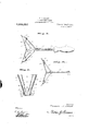
- Figure 1 is a, si ;le.elevatio-n of the device, the mold being in closed position;
- Fig. 2 is a plan view of the device, the mold. being in open position;
- Fig. 3 is ahorizontal sectional view taken on the line 33 in Fig. 1, the mold being shown in open position;
- Fig. 5 is o vertical t ansverse sectional View taken through the mold to disclose the cutters therein.
- each mold section i a rearwardly extending plate 17, the said plates being relatively hinged at their rear edges and at apoint diametrically opposite to the front and contacting edges of the mold sections.
- a housing 18 is provided at the apex of the mold, the said housing being preferably made in sections,cne section bemg formed with one of the mold sections 15 and the other section being formed with the other mold section 15, a pluralitof cutters 19 being journaled in the housing 18, one cutter being provided for each mold section 15 with the blades or sharpened portions of the cutters extending into the mold 14 as shown, suitable toothed wheels 20 being lceved to the cutters 19 adjacent their points ()1.
- Spenings 21 are provided in the sections of the housing 18 and idably extending therethrough are racks 529., the teeth of the said racks being in mesh with the toothed wheels 20 ot the cutters 1'9, the said racks being arranged to extend rearwardlv on both sides of the.
- the forward end of the tongue is normally spaced a distance from the rear edges of the plates 17 and in the use of the device described, the article is grasped by the handle 11 and dipped into the cream to till the mold 14-, it being readily seen that the cream forced into the mold will assume a conical shape.
- the holder made of baked batter as mentioned heretofor, is 'placed beneath the mold and pressure is brought against the thumb piece 26, thus operating the lever 25 against the action of the spring 27.
- a mold comprising separable mold sections having pivotal connection with the said members, plates formed with the mold sections and hinged at their rear edges, cutters jonrnaled on the said mold sections, a spring-engaged lever mounted to swing on the said bar, an actuating bar having connertion with the said lever and terminating at the forward end in a tongue movable with the actuating bar to engage the rear edges of the said platcs,and racks extending forwardly from the said actuating bar and having connection with the said cutters.
- an ice cream cone disher the combination with a handled bar. of spring-like members eXtendcCl from the forward end of the bar, a mold comprising separable mold sections having pivotal connection with the said members, plates formed with the mold sections and hinged at their rear edges, cutters journaled on the said mold sections, a spring-engaged lever mounted to swing on the said bar, anactuating bar having con nection with the said lever and terminating at the forward end in a tongue movable with the actuating bar to engage the rear edges of the said plates, racks having connection with the said actuating bar, and toothed wheels keyed to the said cutters anl in mesh with the teeth of the said racks.
- the comhinatim Will a handledbar, of spring-like members extended from the forward end of the bar, a mold comprising separable mold sections having pivotal connection with the said members,,plates formed with the mold sections and hii'iiged at their rear edges, cutters journaled on the said mold sections, a spring-engaged lever mounted to swing on the said bar, an actuating bar having connection.
Description
T. LBRANDT.
ICE CREAM GONE DISHER.
APPLICATION FILED JULY 10,1912. ggg gg Patented Aug. 5, 1913.
2 SHEETSSHEET 1.
maullvwemtoa Theodore J final; d5
T. J. BRANDT.
ICE CREAM GOES}: DISHER. APPLICATION FILED JULY10,1912.
Patented Aug. 5, 1915.
2 SHEETSSHBET 2.
THEODORE J. BRANDT, T5 GRESHATJI, OREGON.
KflE-CREAD'LCONE IFESHER.
Specification of Letters Patent.
Application filed July 10, 1912. Serial N0. 708,616.
To all whom it may concern Be it known that I, Tnnonoan JI BRANDT, a. citizen of the United States, residing at Gresham, in the county of lvlultnomah and State of Oregon, have invented new and useful improvements in lce- Cream- Cone Dishers, of which the following is a. speci fication.
An. object. of the invention is to provide a device for filling cones of ice cream.
The invention embodies, among other teatures, a device for use in forming whatcomnierciallv known an ice-cream cone and which consists of a cone of ice crean'i placed within a cone of batter which has been ureviouslv subjected to a baking process. For this reason the device includes a conical structure or mold formed oi? movable sectionsand into which the ice cream is pressed, after which the sections are moved apart or swung outwardly to release the cone of ice cream from the mold and permit the some to drop into the conical structure oi-holcl-er, i'ormeil of halted hatter.
in the tuilh-cr disclosure of the invention reference is to be had to the accompanying drawings, constituting a part of this speci fication, in which similar characters oi ref-"- erence denote corresponding parts in all the views, and in which:
Figure 1 is a, si ;le.elevatio-n of the device, the mold being in closed position; Fig. 2 is a plan view of the device, the mold. being in open position; Fig. 3 is ahorizontal sectional view taken on the line 33 in Fig. 1, the mold being shown in open position;
l a. horizontal sectional view taken on the line in Fig. 1; and Fig. 5 is o vertical t ansverse sectional View taken through the mold to disclose the cutters therein.
llc'ferriu' more particular y to the views, use is made of bar terminating at one end in handle 11, a plurality of spring-like membeis having rigid connection with the bar 10 a; the forward end thereof and extemlii'ig forwardly for pivotal connection with a mold 14 consisting of a plurality of similar mold sections 15, the mold 14 being conical in shape with one of the members 13 having pivotal connection with each of. the said mold sections, suitable straps 16 being rigidly secured to the mold sections and engaged by the forwald nds of the members 13 to form the pivotal c tion between the mold sections of the inembcic 13.
Formed with each mold section i a rearwardly extending plate 17, the said plates being relatively hinged at their rear edges and at apoint diametrically opposite to the front and contacting edges of the mold sections. A housing 18 is provided at the apex of the mold, the said housing being preferably made in sections,cne section bemg formed with one of the mold sections 15 and the other section being formed with the other mold section 15, a pluralitof cutters 19 being journaled in the housing 18, one cutter being provided for each mold section 15 with the blades or sharpened portions of the cutters extending into the mold 14 as shown, suitable toothed wheels 20 being lceved to the cutters 19 adjacent their points ()1. connection with the housing 18 Spenings 21 are provided in the sections of the housing 18 and idably extending therethrough are racks 529., the teeth of the said racks being in mesh with the toothed wheels 20 ot the cutters 1'9, the said racks being arranged to extend rearwardlv on both sides of the. plates 17 of the mold 1d, and having pivotal connection at their rear ends with an actuating bar provided with an inte grill, forwardly extending tongue 24, the said tongue being interposed between the racks :22 as shown, the rear end of the actusting bar 23 being arranged for pivotal 0on nection with a lever 25 mounted to swing on the bar 10, immediately in front of the non- (lle 11, the upper end oi" the said lever being bent rearwardly to form thumb piece 26 and the said lever being normally held in vertical position by an expansible spring 27 havin an end thereof secured to the bar 10 and the other end thereof engaging the lever 25.
The forward end of the tongue is normally spaced a distance from the rear edges of the plates 17 and in the use of the device described, the article is grasped by the handle 11 and dipped into the cream to till the mold 14-, it being readily seen that the cream forced into the mold will assume a conical shape. filled with ice cream, the holder, made of baked batter as mentioned heretofor, is 'placed beneath the mold and pressure is brought against the thumb piece 26, thus operating the lever 25 against the action of the spring 27. The lower end of the lever 25 Will thus be thrust forwardly and Will impart a forward movement to the actuat- When the mold has been properly int." bar 23 which in turn will move the racks 92 forwardly and over the toothed wheels 20, thus operating the cutters 19 in the mold 1- to loosen the cone of cream from the inner face of the mold. At the moment the cutters have been operated, the continued forward movement of the actuating bar will bring the forward end of the tongue 24: into engagementwith therear edges of the plates 17, thus bringing pressure to bear on the plates at their point of hinging and causing the mold 1% to separate, the mold section 15 constituting the mold 14 being relatively movable in an out ward direction a sufficient distance to permit 'thecone of ice cream to drop into the baked batter holder. it being understood that the mold sections, in moving outwardly, are
operated against the spring-like action of the members 13 so that when pressure is released on the lever 25, the action of the spring 97 will return the racks 22, and consequently The cutters 19, to normal position while the sprinedike action of the members '13 will cause the mold sections 15 to return to normal or closed position and form the mold 1a, the device being new in position to be again dipped into the cream for the purpose of forming another cone of ice cream.
lt will he understood that I do not limit myself to the construction as disclosed herein and shown in the (h-airings and that various changes may be made without departing from the spirit of the invention, the scope of the invention being defined in the appended claims.
Having thus described my invention, I
claim:
1. In an ice cream cone disher, the combination with a handled bar. of"'spring-like members extended from the forward end of the bar. a mold comprising separable mold sections having pivotal connection with the said members, plates formed with the mold sections and hinged at their rear edges, cutters jonrnaled on the said mold sections, a spring-engaged lever mounted to swing on the said bar, an actuating bar having connertion with the said lever and terminating at the forward end in a tongue movable with the actuating bar to engage the rear edges of the said platcs,and racks extending forwardly from the said actuating bar and having connection with the said cutters.
2. ln an ice cream cone disher, the combination with a handled bar. of spring-like members eXtendcCl from the forward end of the bar, a mold comprising separable mold sections having pivotal connection with the said members, plates formed with the mold sections and hinged at their rear edges, cutters journaled on the said mold sections, a spring-engaged lever mounted to swing on the said bar, anactuating bar having con nection with the said lever and terminating at the forward end in a tongue movable with the actuating bar to engage the rear edges of the said plates, racks having connection with the said actuating bar, and toothed wheels keyed to the said cutters anl in mesh with the teeth of the said racks.
3. In an ce cream cone dishcr, the comhinatim Will a handledbar, of spring-like members extended from the forward end of the bar, a mold comprising separable mold sections having pivotal connection with the said members,,plates formed with the mold sections and hii'iiged at their rear edges, cutters journaled on the said mold sections, a spring-engaged lever mounted to swing on the said bar, an actuating bar having connection. with the said lever and terminating at the forward end in a tongue movable with the actuating bar to engage the rear edges of the said plates, racks having connection with the said actuating bar, toothed wheels keyed to the said cutters and in mesh with the teeth of the said racks, and a housing;- for the said toothed wheels, the said housing consisting of two parts formed with the said mold sections and having the said racks slidable therein.
4. In an ice cream cone disher, the combination with'a handled bar, of spring lilze members extending forwardly from the bar, similar mold sections having pivotal connection with the said members, plates formed with the mold sections and hinged at their rear edges, an actuating bar movable to engage the said plates and swing the mold sections apart, a lever having piv otal connection with the said bar and the said actuating bar for moving the actuating bar forwardly to engage the said plates,
cutters journaled on the said mold sections, l
and means movable on the said actuating ba and engaging the said cutters to operate the same.
In testimony whereof I my signature in presence of two witnesses.
THEODORE J. BRANDT. \litnesses:
SILAS W. THORNTON, MARGARET THORNTON.
Priority Applications (1)
| Application Number | Priority Date | Filing Date | Title |
|---|---|---|---|
| US70861612A US1069226A (en) | 1912-07-10 | 1912-07-10 | Ice-cream-cone disher. |
Applications Claiming Priority (1)
| Application Number | Priority Date | Filing Date | Title |
|---|---|---|---|
| US70861612A US1069226A (en) | 1912-07-10 | 1912-07-10 | Ice-cream-cone disher. |
Publications (1)
| Publication Number | Publication Date |
|---|---|
| US1069226A true US1069226A (en) | 1913-08-05 |
Family
ID=3137463
Family Applications (1)
| Application Number | Title | Priority Date | Filing Date |
|---|---|---|---|
| US70861612A Expired - Lifetime US1069226A (en) | 1912-07-10 | 1912-07-10 | Ice-cream-cone disher. |
Country Status (1)
| Country | Link |
|---|---|
| US (1) | US1069226A (en) |
-
1912
- 1912-07-10 US US70861612A patent/US1069226A/en not_active Expired - Lifetime
Similar Documents
| Publication | Publication Date | Title |
|---|---|---|
| US1110946A (en) | Meat-chopper. | |
| US1069226A (en) | Ice-cream-cone disher. | |
| US1127548A (en) | Corn-cutter. | |
| US1938733A (en) | Nut cracker | |
| US850582A (en) | Culinary utensil. | |
| US2074337A (en) | Nutcracker | |
| US1798490A (en) | Ice-cream disher | |
| US836440A (en) | Culinary utensil. | |
| US1138533A (en) | Ice-cream-cone disher. | |
| US962576A (en) | Rake. | |
| US1688595A (en) | Ice-cream scoop | |
| US1112802A (en) | Ice-cream-cone scoop. | |
| US1132334A (en) | Rake. | |
| US874286A (en) | Machine for working the soil. | |
| US2236606A (en) | Dispensing fork | |
| US1481890A (en) | Dipper or scoop | |
| US1125534A (en) | Self-cleaning weed-cutter. | |
| US1242436A (en) | Nutcracker. | |
| US1141682A (en) | Ratchet driving mechanism for cutters. | |
| US1320885A (en) | Scoop | |
| US1024240A (en) | Culinary implement. | |
| US550556A (en) | Turner for griddle-cakes | |
| US1177961A (en) | Wrench. | |
| US1289989A (en) | Disk harrow. | |
| US1176636A (en) | Spade-cleaner. |