US10691843B2 - System and method for CNC machines and software - Google Patents
System and method for CNC machines and software Download PDFInfo
- Publication number
- US10691843B2 US10691843B2 US16/038,016 US201816038016A US10691843B2 US 10691843 B2 US10691843 B2 US 10691843B2 US 201816038016 A US201816038016 A US 201816038016A US 10691843 B2 US10691843 B2 US 10691843B2
- Authority
- US
- United States
- Prior art keywords
- machine
- physical
- work
- piece
- rendering
- Prior art date
- Legal status (The legal status is an assumption and is not a legal conclusion. Google has not performed a legal analysis and makes no representation as to the accuracy of the status listed.)
- Expired - Fee Related, expires
Links
Images


Classifications
-
- G—PHYSICS
- G05—CONTROLLING; REGULATING
- G05B—CONTROL OR REGULATING SYSTEMS IN GENERAL; FUNCTIONAL ELEMENTS OF SUCH SYSTEMS; MONITORING OR TESTING ARRANGEMENTS FOR SUCH SYSTEMS OR ELEMENTS
- G05B19/00—Program-control systems
- G05B19/02—Program-control systems electric
- G05B19/18—Numerical control [NC], i.e. automatically operating machines, in particular machine tools, e.g. in a manufacturing environment, so as to execute positioning, movement or co-ordinated operations by means of program data in numerical form
- G05B19/414—Structure of the control system, e.g. common controller or multiprocessor systems, interface to servo, programmable interface controller
-
- G—PHYSICS
- G06—COMPUTING OR CALCULATING; COUNTING
- G06F—ELECTRIC DIGITAL DATA PROCESSING
- G06F30/00—Computer-aided design [CAD]
- G06F30/10—Geometric CAD
- G06F30/12—Geometric CAD characterised by design entry means specially adapted for CAD, e.g. graphical user interfaces [GUI] specially adapted for CAD
-
- G—PHYSICS
- G05—CONTROLLING; REGULATING
- G05B—CONTROL OR REGULATING SYSTEMS IN GENERAL; FUNCTIONAL ELEMENTS OF SUCH SYSTEMS; MONITORING OR TESTING ARRANGEMENTS FOR SUCH SYSTEMS OR ELEMENTS
- G05B19/00—Program-control systems
- G05B19/02—Program-control systems electric
- G05B19/18—Numerical control [NC], i.e. automatically operating machines, in particular machine tools, e.g. in a manufacturing environment, so as to execute positioning, movement or co-ordinated operations by means of program data in numerical form
- G05B19/4093—Numerical control [NC], i.e. automatically operating machines, in particular machine tools, e.g. in a manufacturing environment, so as to execute positioning, movement or co-ordinated operations by means of program data in numerical form characterised by part programming, e.g. entry of geometrical information as taken from a technical drawing, combining this with machining and material information to obtain control information, named part program, for the NC machine
- G05B19/40937—Numerical control [NC], i.e. automatically operating machines, in particular machine tools, e.g. in a manufacturing environment, so as to execute positioning, movement or co-ordinated operations by means of program data in numerical form characterised by part programming, e.g. entry of geometrical information as taken from a technical drawing, combining this with machining and material information to obtain control information, named part program, for the NC machine concerning programming of machining or material parameters, pocket machining
-
- G—PHYSICS
- G06—COMPUTING OR CALCULATING; COUNTING
- G06F—ELECTRIC DIGITAL DATA PROCESSING
- G06F30/00—Computer-aided design [CAD]
-
- G—PHYSICS
- G05—CONTROLLING; REGULATING
- G05B—CONTROL OR REGULATING SYSTEMS IN GENERAL; FUNCTIONAL ELEMENTS OF SUCH SYSTEMS; MONITORING OR TESTING ARRANGEMENTS FOR SUCH SYSTEMS OR ELEMENTS
- G05B2219/00—Program-control systems
- G05B2219/30—Nc systems
- G05B2219/33—Director till display
- G05B2219/33099—Computer numerical control [CNC]; Software control [SWC]
-
- G—PHYSICS
- G05—CONTROLLING; REGULATING
- G05B—CONTROL OR REGULATING SYSTEMS IN GENERAL; FUNCTIONAL ELEMENTS OF SUCH SYSTEMS; MONITORING OR TESTING ARRANGEMENTS FOR SUCH SYSTEMS OR ELEMENTS
- G05B2219/00—Program-control systems
- G05B2219/30—Nc systems
- G05B2219/36—Nc in input of data, input key till input tape
- G05B2219/36268—From blank and finished entered shape, derive machining features
-
- G—PHYSICS
- G05—CONTROLLING; REGULATING
- G05B—CONTROL OR REGULATING SYSTEMS IN GENERAL; FUNCTIONAL ELEMENTS OF SUCH SYSTEMS; MONITORING OR TESTING ARRANGEMENTS FOR SUCH SYSTEMS OR ELEMENTS
- G05B2219/00—Program-control systems
- G05B2219/30—Nc systems
- G05B2219/36—Nc in input of data, input key till input tape
- G05B2219/36284—Use of database for machining parameters, material, cutting method, tools
-
- G—PHYSICS
- G06—COMPUTING OR CALCULATING; COUNTING
- G06F—ELECTRIC DIGITAL DATA PROCESSING
- G06F2119/00—Details relating to the type or aim of the analysis or the optimisation
- G06F2119/18—Manufacturability analysis or optimisation for manufacturability
-
- Y—GENERAL TAGGING OF NEW TECHNOLOGICAL DEVELOPMENTS; GENERAL TAGGING OF CROSS-SECTIONAL TECHNOLOGIES SPANNING OVER SEVERAL SECTIONS OF THE IPC; TECHNICAL SUBJECTS COVERED BY FORMER USPC CROSS-REFERENCE ART COLLECTIONS [XRACs] AND DIGESTS
- Y02—TECHNOLOGIES OR APPLICATIONS FOR MITIGATION OR ADAPTATION AGAINST CLIMATE CHANGE
- Y02P—CLIMATE CHANGE MITIGATION TECHNOLOGIES IN THE PRODUCTION OR PROCESSING OF GOODS
- Y02P90/00—Enabling technologies with a potential contribution to greenhouse gas [GHG] emissions mitigation
- Y02P90/02—Total factory control, e.g. smart factories, flexible manufacturing systems [FMS] or integrated manufacturing systems [IMS]
-
- Y02P90/265—
Definitions
- the present disclosure may include embodiments that were funded in part by government grant DARPA-BAA-11-19 MENTOR.
- the present disclosure relates generally to computer numerical control (CNC) machines and more particularly, but not exclusively, to CNC machines and software for CNC machines.
- CNC computer numerical control
- FIG. 1 is an exemplary perspective drawing illustrating an embodiment of a CNC milling machine in accordance with one embodiment.
- FIG. 2 is an exemplary network diagram illustrating an embodiment of a network comprising a milling machine, a laser cutter, and a CNC cutting machine in accordance with an embodiment.
- FIG. 3 is an exemplary data flow diagram illustrating data flow between a mill and a user device in accordance with one embodiment.
- FIG. 4 is an exemplary flow chart illustrating an embodiment of rendering a machine and work-piece.
- FIG. 5 is an exemplary data flow diagram illustrating data flow between a mill and a user device in accordance with another embodiment.
- FIG. 6 is an exemplary data flow diagram illustrating data flow between a mill and a user device in accordance with a further embodiment.
- FIG. 7 is an exemplary flow chart illustrating an embodiment of rendering a work-piece.
- FIG. 8 is an exemplary embodiment of a user interface depicting a rendering of a machine and work-piece.
- FIG. 9 is another exemplary embodiment of a user interface depicting a rendering of a machine and work-piece.
- FIG. 10 is still another exemplary embodiment of a user interface depicting a rendering of a machine and work-piece.
- FIG. 11 is a further exemplary embodiment of a user interface depicting a rendering of a machine and work-piece.
- FIG. 12 is a still further exemplary embodiment of a user interface depicting a rendering of a machine and work-piece.
- FIGS. 13 a - b depict an embodiment of a user interface for three dimensional editing of a virtual work-piece.
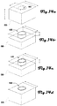
- FIGS. 14 a - d depict another embodiment of a user interface for three dimensional editing of a virtual work-piece
- FIG. 1 is an exemplary perspective drawing illustrating an embodiment of a CNC milling machine 100 in accordance with one embodiment.
- the mill 100 comprises a housing 105 that includes four sidewalls 110 ; namely, a front-wall 110 A, two peripheral walls 110 B, 110 C and a rear wall 110 D that collectively define a cavity 112 .
- the sidewalls further comprise windows 115 ; for example, the front-wall 100 A comprises a front window 115 A, the peripheral walls 110 B, 110 C comprise peripheral windows 115 B, 115 C.
- the peripheral walls 110 B, 110 C further comprise handles 120 A, 120 B at respective top ends of the peripheral walls 110 B, 110 C.
- the mill 100 may also comprise internal housing components that provide for three dimensional movement of an endmill 155 relative to a work-piece. As shown in FIG. 1 , the mill 100 further comprises an X-carriage 125 that translates within the cavity 112 on a pair of X-rods 130 that extend between the peripheral walls 110 B, 110 C. Additionally a Z-carriage 135 translates on a pair of Z-rods 140 disposed within the X-carriage. The Z-carriage 135 holds a motor 145 that rotates a chuck 150 that holds the endmill 155 . A Y-bed 160 translates along Y-rods 165 that extend between the front and rear walls 110 A, 110 D.
- the X-carriage 125 provides for movement of the endmill 155 along an X-axis and the Z-carriage 135 provides for movement of the endmill 155 along a Z-axis.
- the Y-bed 160 is configured to move a work-piece coupled to the Y-bed 160 along a Y-axis. Accordingly, the endmill 155 is operable to move in three dimensions relative to a work-piece on the bed 160 .
- Various components of the mill 100 may be housed within a cavity below the bed 160 , and a fan (not shown) may vent to a bottom of the mill 100 , and vented air may be expelled from a plurality of vent slots 175 at the bottom of the walls 110 and defined by a portion of the walls 110 that may further optionally include a plurality of feet 170 (e.g., feet 170 A, 170 B, 170 C) that set the mill 100 off from a surface.
- a fan (not shown) may vent to a bottom of the mill 100 , and vented air may be expelled from a plurality of vent slots 175 at the bottom of the walls 110 and defined by a portion of the walls 110 that may further optionally include a plurality of feet 170 (e.g., feet 170 A, 170 B, 170 C) that set the mill 100 off from a surface.
- feet 170 e.g., feet 170 A, 170 B, 170 C
- the mill 100 may be a desktop mill that is light, portable, and usable in homes and small workshops.
- some embodiments of a mill 100 have dimensions of approximately 10 inches cubed, with a weight of approximately 15 pounds.
- Such embodiments may provide for improved handling and configuration of a mill 100 .
- the mill 100 may be operated in a configuration with the feet 170 resting on a surface, it may also be desirable to rotate the mill 100 so that any one of the walls 110 is facing down, or such that the top of the mill 100 is facing down.
- Such configurations may be desirable because cuttings generated by the mill 100 during milling of a work-piece can fall through the windows 115 .
- Such configurations are not possible with conventional mills due to the size and weight of such mills and also due to incompatible shape and location of windows.
- FIG. 1 depicts open windows 115 on walls 110 of the housing 105 ; however, in some embodiments, the windows may be covered with a transparent or opaque material. In some embodiments, removable window coverings (not shown) may be selectively coupled with the windows 115 . For example, one or more coverings may be coupled with the housing 105 via magnets, slots, pins, hooks or the like.
- a mill 100 may be any suitable size and shape, and the embodiments of a mill shown and described herein should not be considered to be limiting as to the sizes and shapes of a mill 100 in accordance with the present invention.
- FIG. 2 is an exemplary network diagram illustrating an embodiment of a network 200 comprising a milling machine 100 , a CNC blade cutting machine 220 , a laser cutter 230 , and a user device 240 that are operably connected via a network 250 in accordance with an embodiment.
- the mill 100 may be any suitable mill including the mill 100 described and shown in FIG. 1 .
- the blade cutter 220 and laser cutter 230 may be any suitable blade or laser based cutting device.
- the user device 240 may include a laptop computer as depicted in FIG. 2 ; however, any suitable user device may be used in various embodiments, including a desktop computer, smart phone, gaming device, smart glasses, smart watch, or the like. Other suitable devices may be present in such a network, including any suitable machining device, paper printer, three-dimensional printer, robot, and the like, without limitation. Devices that may part of a network 200 in some embodiments, may be absent in some embodiments, or may be present in plurality in some embodiments.
- the network 250 may comprise any suitable wired or wireless network, including the Internet, a local area network (“LAN”), a wide area network (“WAN”) a Wi-Fi network, a BlueTooth network or the like.
- suitable devices 100 , 220 , 230 , and the like may, be directly connected to a user device 240 via a Universal Serial Bus (“USB”) connection.
- USB Universal Serial Bus
- a user that desires to manufacture a given product or part may create a network 200 of manufacturing devices that can be controlled via a single device and interface.
- any suitable device may be included or removed from the network 200 , and the identity and configuration of the connected manufacturing devices may be automatically determined as such devices join the network.
- Customized device networks 200 may be created for certain manufacturing applications 200 .
- a user may control a plurality of desktop manufacturing devices via a user device 240 to modify one or more work-piece in the plurality of manufacturing devices.
- Some embodiments include a device network 200 where all of the manufacturing devices, or the like, are proximate to the user device (e.g., in the same room).
- any of the devices 100 , 220 , 230 , 240 may be in disparate locations compared to one another.
- a user device 240 may control a plurality of manufacturing devices remotely over the Internet, and the manufacturing devices may or may not be in the same location from user device 240 or from each other.
- the following figures depict systems and methods for controlling and interacting with one or more manufacturing device. While the following example embodiments relate primarily to a mill 100 , the systems and methods discussed may be applied to any suitable network configuration having one or more suitable device or machine.
- FIG. 3 is an exemplary data flow diagram illustrating data flow between a mill 100 and a user device 240 in accordance with one embodiment.
- the data flow begins at 305 where a machine identifier is received from the mill 100 at the user device 240 , where a machine profile is determined at 310 .
- a machine identifier may be any suitable identifier in various embodiments.
- a machine identifier may be a global unique identifier (e.g., a Medium Access Control (“MAC”) address) that uniquely identifies a given device or machine.
- MAC Medium Access Control
- a machine identifier may include an indicator associated with a make, model, serial number, configuration, or the like, of a device or machine in addition to or in lieu of a MAC address.
- a portion of a machine identifier may be associated with a machine or device profile.
- a machine profile may include various information about a given machine, or a model of machine, including physical dimensions; three dimensional rendering data; date regarding possible machine configurations; machine limitation data; motor strength data; motor speed data; compatible endmill data; minimum and maximum chuck size data; and the like.
- Such a profile may include any suitable data that provides for rendering and/or operating of a machine as further described herein.
- the user device 240 may store a plurality of machine or device profiles and use suitable profile data based on one or more device or machine that may be operably connected with the user device 240 .
- machine or device profiles may be stored on a remote device (e.g., a server) and such profile data may be retrieved by the user device 240 when necessary. For example, where the user device 204 receives a machine identifier, a determination may be made that a suitable machine profile is not stored on the user device 240 , and a suitable machine profile present on a remote device may be identified and used either remotely or downloaded to the user device 240 .
- a rendering of the mill 100 is presented on the user device 240 , at 315 .
- work-piece data is received at the user device 240
- a rendering of the mill 100 is presented that further includes a work-piece rendering based on the received work-piece data.
- User interfaces and presentation of machine or device renderings including a work-piece rendering is illustrated and discussed in further detail herein. (See e.g., FIGS. 8-14 d )
- work-piece data may be input at the user device 240 .
- a user may input dimensions of a work-piece or other data that describes a work-piece in three dimensions.
- height, length and width may be provided by a user.
- work-piece data may comprise CAD data, parametric data, or other suitable data that indicates the shape and size of a work-piece.
- work-piece data may include data generated by a mill 100 or user device 240 .
- a work-piece may be cut by a mill 100 , and such cutting of the work-piece may be tracked such that when the cut work-piece is transferred to second machine or mill, the shape and cutting that occurred on the work-piece can be rendered in association with the second machine or mill.
- Such data may be stored on a server, a user device 240 , or on a suitable machine or device.
- work-piece data may be loaded from a memory on the user device 240 , or may be received from a server, machine or device.
- work-piece data may be physically or visually determined by sensors associated with the mill 100 .
- Work-piece data may also include data regarding one or more material that comprises a work-piece. For example, in various embodiments, it may be desirable to account for material properties when generating a cutting path and method for cutting a work-piece. Different materials (e.g., wood and metal) may have different physical properties that may require certain endmills, endmill rotational speed, endmill translational speed, lubrication, heat dissipation, or the like.
- a user may select one or more materials or characteristics of a work-piece.
- the user may generally indicate that a work-piece consists of a class of materials, such as wood or metal or may more specifically indicate the type of material that the work-piece is made of, such as by specifying that is made of aluminum or pine wood.
- materials or characteristics of a work-piece may be physically or visually determined by sensors associated with the mill 100 .
- a work-piece may comprise a plurality of materials in any suitable configuration, and data specifying the location and type of the plurality of materials and/or other data describing a given work-piece may be provided to the user device 240 .
- work-pieces may comprise one or more layers and be available to users in specific dimensions and configurations that are associated with a work-piece profile or the like. Users may then provide a work-piece profile or indicator, which comprises the specifications of the standardized work-piece.
- Work-piece data may also include data regarding position of the work-piece relative to the mill 100 , or the like.
- a work-piece may be coupled to the bed 160 of a mill 100 , and the work-piece may be milled by movement of the bed 160 and work-piece relative to movement of the endmill 155 .
- the position of the work-piece on the bed 160 must be known.
- Position data of a work-piece on the bed 160 may be obtained in any suitable way.
- a user may measure the location of the work-piece, the work-piece may be held by a frame, guide or template that provides for indication of position on the bed 160 , or position may be physically or visually determined by sensors associated with the mill 100 .
- machine state data is sent from the mill 100 to the user device 240 , at 330 , and a real-time rendering of the mill 100 is presented that is further based on the machine state data, at 345 .
- a real-time rendering of the work-piece is presented based on real-time machine state data.
- Machine state data may be any suitable data related to the position of portions of the mill 100 or component configurations of the mill 100 .
- machine state data may comprise an indication of the position of the X-carriage 125 on the X-rods; the position of the Z-carriage 135 on the Z-rods 140 ; and the position of the Y-bed 160 on the Y-rods.
- Machine state data may also comprise data such as an identifier of an endmill 155 that may be present in the chuck 150 , position of the endmill 155 , an identifier of a frame, guide or template present on the bed 160 , or the like.
- a rendering of the mill 100 may be generated that replicates the current state of the mill 100 . (See e.g., FIGS. 8-12 ). This may be desirable so that a user can view and manipulate a rendering that directly corresponds to the physical mill 100 .
- machine state data may be stored on a memory present in the mill 100 . In other embodiments, machine state data may be stored in removable memory, in other network locations or other locally or network-accessible locations.
- a rendering of the work-piece being milled in real-time See e.g., FIGS. 9 and 10 .
- the cutting of a work-piece may be determined and rendered to a user. It may therefore be assumed based on position data that the endmill is cutting (or has cut) the work-piece, when a portion of the endmill contacts the rendered work-piece; when a portion of the rendered endmill is within the boundaries of the rendered work-piece, or when a portion of the rendered endmill has previously been in contact with or within the boundaries of the rendered work-piece. Accordingly, cuts in the work-piece may be determined and rendered in real-time.
- present and historical work-piece state data may be stored in the mill 100 and/or at the user device 240 .
- real-time machine state data is received by the user device 240 and a real-time rendering of the mill 100 based on the real-time machine state data is presented.
- real-time machine state data may comprise an indication of the position of and movement of the X-carriage 125 on the X-rods; the position of and movement of the Z-carriage 135 on the Z-rods 140 ; and the position of and movement of the Y-bed 160 on the Y-rods.
- Real-time machine state data may also comprise data such as an identifier of an endmill 155 that may be present in the chuck 150 , the position and movement of an endmill 155 , an identifier of a frame, guide or template present on the bed 160 , or the like.
- a real-time rendering of the mill 100 may be generated that replicates the current state of the mill 100 , including real-time rendering of movement of various portions of the mill 100 . This may be desirable so that a user can view and manipulate a rendering that directly corresponds to the physical mill 100 in real-time.
- real-time machine state data may be stored on a memory present in the mill 100 . While machine state data and real-time machine state data may be determined based on the indicated position of moving components of the mill 100 , machine state data and real-time machine state data may also or alternatively be physically or visually determined by sensors associated with the mill 100 .
- FIG. 4 is an exemplary flow chart illustrating an embodiment of a method 400 of rendering a machine and work-piece.
- the method 400 begins in block 405 where a machine identifier is received, and in block 410 , a machine profile is determined. In block 415 , a rendering of the machine is presented based on the determined user profile. In block 420 , work-piece data is received, and in block 425 , a rendering of the machine is presented that further includes a rendering of a work-piece. In block 430 , machine state data is received, and in block 435 , a rendering of the machine is presented that further includes the configuration of the machine. In block 440 , real-time machine state data is received, and in block 445 , a rendering of the machine is presented that is further based on real-time machine state data.
- the method 400 continues to decision block 450 , where a determination is made whether real-time machine state data indicates a work-piece change, and if so, the method 400 continues to block 455 where the rendering of the work-piece is updated based on the real-time machine state data and the method 400 continues to decision block 460 .
- the method 400 continues to decision block 460 where a determination is made whether further real-time machine state data is received. If no further real-time machine state data is received, the method 400 continues to block 465 where the currently presented rendering is maintained, and the method 400 cycles back to decision block 460 , where the method 400 waits until further real-time machine state data is received, and if so, the method 400 cycles back to block 445 where a rendering based on the further real-time machine state data is received.
- a user device 240 may continuously receive real-time machine state data from a mill 100 and display a real-time rendering of the mill 100 as it moves and cuts a work-piece.
- the rendering may directly correspond to the movement and cutting that is occurring at the mill 100 and cuts to the work-piece may be determined based on a known location of the work-piece coupled to a portion of the mill 100 , based on known movement of portions of the mill 100 , and based on known location of the endmill 155 .
- FIG. 5 is an exemplary data flow diagram illustrating data flow between a mill 100 and a user device 240 in accordance with another embodiment wherein the mill 100 is controlled via the user device 240 .
- the communications begin at 505 where a desired configuration of the mill 100 is indicated via an interface, and at 510 , machine control instructions are generated based on the indicated desired configuration.
- the machine control instructions are sent to the mill 100 , at 515 and the mill configuration is modified at 520 .
- real-time machine state data is sent to the user device, at 525 , and a real-time rendering of the mill 100 is presented based on the real-time machine data, at 530 .
- a user may indicate a desired configuration of the mill in various suitable ways.
- the user device 240 may display an interface with a proportional three dimensional rendering that shows the position of physical mill 100 .
- a user may move the mill in real-time or near-real-time by clicking buttons, holding buttons dragging portions of the three dimensional rendering, or the like.
- the physical mill 100 will move in kind in real-time or near-real time.
- both the physical mill 100 and rendered mill will move in unison or near-unison.
- a desired sequence of configurations may be indicated and then provided to the mill 100 for execution.
- a user may provide a series of movement instructions via the interface, and these desired movements may be depicted by the rendering of the mill, but not yet performed by the physical mill 100 .
- the desired set of instructions may then be provided to the mill 100 (e.g., by clicking an “execute” or “send” button), and the mill 100 may then perform the instructed movements and the rendering of the mill on the user device 240 may depict such actions in real-time or near real-time.
- a desired configuration of the mill 100 may be indicated in various suitable ways.
- a user may directly import a CAD file that corresponds with a desired final cutting state of a work-piece.
- the user device 240 may determine a cutting path that mills the work-piece into the desired shape, and such a generated cutting path may be provided to the mill 100 .
- the cutting of the work-piece may be rendered in real-time or near-real time by the user device 240 .
- a user may edit a three dimensional rendering of a work-piece as described herein using graphical user interface tools or otherwise, and such editing may be used to generate a cutting path, which in turn can be provided to the mill 100 .
- FIG. 6 is an exemplary data flow diagram illustrating data flow between the mill 100 and user device 240 in accordance with a further embodiment, wherein a rendering of a work-piece is modified to generate a cutting path for the mill 100 .
- the user may designate a cutting path using other known data input operations, including through for example, a command line interface or customized script.
- the communications begin at 605 where a rendering of a work-piece is presented, and at 610 edits to the work-piece are received.
- a three dimensional rendering of a work-piece may be modified via an interface presented on the user device 240 .
- the modifications to the rendered work-piece may be used to determine or generate a cut path that will mill the work-piece in the she shape indicated by the modified rendering.
- the physical limitations, constraints or abilities of the mill 100 and/or endmill may be used when providing limitations, constraints or abilities for editing or modifying a work-piece rendering.
- some combinations of a mill 100 and endmill 155 may be incapable of forming overhanging structures, or the like. Accordingly, the ability to create such structures when editing a work-piece rendering may be prevented.
- a work-piece may have physical characteristics that make certain features structurally unsound or that cannot be produced within the tolerances of a given mill 100 and endmill 155 combinations. Accordingly, the ability to create such structures when editing a work-piece rendering may be prevented or a user may be warned against generating such structures.
- any suitable device or machine profile data may be used to determine limitations, constraints or abilities for editing or modifying a work-piece rendering, and such limitations, constraints or abilities for editing or modifying a work-piece rendering may be changed based on a given combination or configuration of a machine, device, endmill, cutting implement or the like.
- FIG. 7 is an exemplary flow chart illustrating an embodiment of a method 700 for rendering a work-piece.
- the method begins in block 705 where a rendering of a machine including a work-piece is presented, and in block 710 , edits to the work-piece are received.
- a work-piece cut path is generated based on the received edits to the rendering of the work-piece, and in block 720 , a rendering of the work-piece cut path associated with the rendering of the work-piece is presented. Presentation of a work-piece cut path is described and illustrated in further detail herein. (See e.g., FIGS. 8-10 ).
- machine control instructions are generated based on the work-piece cut path, and in block 730 work-piece cutting is initiated.
- real-time machine state data is received, and in block 740 a rendering of the work-piece cutting based on real-time machine state data is presented.
- the method 700 continues to decision block 745 , where a determination is made whether real-time machine state data indicates a work-piece change, and if so, the method 700 continues to block 750 where the rendering of the work-piece is updated based on the real-time machine state data and the method 700 continues to decision block 755 .
- the method 700 continues to decision block 755 where a determination is made whether further real-time machine state data is received. If no further real-time machine state data is received, the method 700 continues to block 760 where the currently presented rendering is maintained, and the method 700 cycles back to decision block 755 , where the method 700 waits until further real-time machine state data is received, and if so, the method 700 cycles back to block 740 where a rendering based on the further real-time machine state data is received.
- a user device 240 may continuously receive real-time machine state data from a mill 100 and display a real-time rendering of the mill 100 as it moves and cuts a work-piece.
- the rendering may directly correspond to the movement and cutting that is occurring at the mill 100 and cuts to the work-piece may be determined based on a known location of the work-piece coupled to a portion of the mill 100 ; may be determined based on known movement of portions of the mill 100 ; and may be determined based on a known location of the endmill 155 .
- FIGS. 8-12 depict exemplary user interfaces 800 A-E in accordance with various embodiments.
- the interface 800 A depicted in FIG. 8 illustrates an example of an interface depicting a preview of a cut work-piece.
- the interface 800 includes interface window 801 that presents a rendering of a machine 805 , which includes an endmill 855 , a bed 860 , a work-piece 880 coupled with the bed 860 , and a cut path 886 imposed on the work-piece 880 .
- the interface further includes a first menu 882 that may comprise selections and indications related to the work-piece, the endmill, cutting of the work-piece, and a preview of cutting the work-piece.
- the embodiment of the interface 800 A shown in FIG. 8 depicts an example of the interface 800 where a preview of the cut work-piece 880 is generated and displayed along with a generated and displayed cut path 886 .
- the endmill 855 is shown in a home position before the cutting begins, and the cut path line 886 shows where the endmill 855 will travel to generate the cut work-piece.
- Certain rendered portions of the machine 805 may be shown in more or less detail, and may be depicted as transparent, translucent or opaque in various embodiments.
- the endmill 855 , work-piece 880 and bed 860 may be depicted as being partially translucent so that their relation to other portions of the machine can be perceived. Such other portions of the machine 805 may be depicted in less detail as shown in FIG. 8 .
- the interface may depict a rendering of a machine 805 during cutting of the work-piece.
- FIG. 9 depicts an embodiment 800 B where the work-piece is being cut, but where the endmill 855 has been raised from the work-piece 880 .
- FIG. 10 depicts and embodiment 800 C where the work-piece 855 is shown cutting the work-piece 880 .
- the machine 805 is depicted before work-piece cut data is imported and displayed.
- the machine 805 is depicted in a pre-setup state.
- the interface 800 and milling machine 100 may be operable without an intermediary numerical control (NC) format.
- the interface and/or the machine 100 may read and/or convert a CAD drawing directly (without need for generating G-code, or the like).
- information that is generated by through user edits made through the interface 800 may be converted and exported directly in formats compatible with CAD programs or other data formats for use in other design or analysis software tools.
- FIG. 13 a depicts one embodiment where a vector drawing (e.g., in .svg format) is imported into the interface 800 ( FIGS. 8-12 ), and a rendering of the work-piece 855 ( FIGS. 8-12 ) and target work-piece state is generated along with a cutting path.
- CAD functionalities in the interface allow the rendering to be edited, which may change the target work-piece state and change the generated cutting path.
- a CAD interface may allow the user to draw and design a cylinder cut 1440 .
- FIG. 14 a depicts a rendered work-piece 880 where a cylindrical cavity 1410 is generated by indicating a circle on a two dimensional plane of the work-piece and extending the circle in a third dimension perpendicular to the two dimensional plane.
- a solid positive cylinder 1420 can be generated as depicted in FIG. 14 b.
- FIG. 14 c depicts a rendered work-piece 880 where a positive cylindrical body 1430 with a central negative cylindrical cavity is generated by further indicating a second circle on a two dimensional plane of the work-piece 880 and extending the circle in a third dimension perpendicular to the two dimensional plane.
- a negative cylindrical body 1430 with a central positive cylindrical body is generated as depicted in FIG. 14 d .
- parametric two-dimensional drawing functions may be used to render and manipulate a work-piece.
Landscapes
- Engineering & Computer Science (AREA)
- Physics & Mathematics (AREA)
- General Physics & Mathematics (AREA)
- Geometry (AREA)
- Human Computer Interaction (AREA)
- Theoretical Computer Science (AREA)
- Manufacturing & Machinery (AREA)
- Automation & Control Theory (AREA)
- Computer Hardware Design (AREA)
- Evolutionary Computation (AREA)
- General Engineering & Computer Science (AREA)
- Architecture (AREA)
- Mathematical Optimization (AREA)
- Pure & Applied Mathematics (AREA)
- Mathematical Analysis (AREA)
- Computational Mathematics (AREA)
- Numerical Control (AREA)
- Software Systems (AREA)
Abstract
Description
Claims (18)
Priority Applications (1)
| Application Number | Priority Date | Filing Date | Title |
|---|---|---|---|
| US16/038,016 US10691843B2 (en) | 2012-07-16 | 2018-07-17 | System and method for CNC machines and software |
Applications Claiming Priority (5)
| Application Number | Priority Date | Filing Date | Title |
|---|---|---|---|
| US201261672205P | 2012-07-16 | 2012-07-16 | |
| US201361879265P | 2013-09-18 | 2013-09-18 | |
| US201461950642P | 2014-03-10 | 2014-03-10 | |
| US14/489,258 US10055512B2 (en) | 2012-07-16 | 2014-09-17 | System and method for CNC machines and software |
| US16/038,016 US10691843B2 (en) | 2012-07-16 | 2018-07-17 | System and method for CNC machines and software |
Related Parent Applications (1)
| Application Number | Title | Priority Date | Filing Date |
|---|---|---|---|
| US14/489,258 Continuation US10055512B2 (en) | 2012-07-16 | 2014-09-17 | System and method for CNC machines and software |
Publications (2)
| Publication Number | Publication Date |
|---|---|
| US20190050498A1 US20190050498A1 (en) | 2019-02-14 |
| US10691843B2 true US10691843B2 (en) | 2020-06-23 |
Family
ID=65275092
Family Applications (2)
| Application Number | Title | Priority Date | Filing Date |
|---|---|---|---|
| US14/489,258 Expired - Fee Related US10055512B2 (en) | 2012-07-16 | 2014-09-17 | System and method for CNC machines and software |
| US16/038,016 Expired - Fee Related US10691843B2 (en) | 2012-07-16 | 2018-07-17 | System and method for CNC machines and software |
Family Applications Before (1)
| Application Number | Title | Priority Date | Filing Date |
|---|---|---|---|
| US14/489,258 Expired - Fee Related US10055512B2 (en) | 2012-07-16 | 2014-09-17 | System and method for CNC machines and software |
Country Status (1)
| Country | Link |
|---|---|
| US (2) | US10055512B2 (en) |
Cited By (5)
| Publication number | Priority date | Publication date | Assignee | Title |
|---|---|---|---|---|
| US20180357047A1 (en) * | 2016-01-27 | 2018-12-13 | Bonsai AI, Inc. | Interface for working with simulations on premises |
| US11762635B2 (en) | 2016-01-27 | 2023-09-19 | Microsoft Technology Licensing, Llc | Artificial intelligence engine with enhanced computing hardware throughput |
| US11775850B2 (en) | 2016-01-27 | 2023-10-03 | Microsoft Technology Licensing, Llc | Artificial intelligence engine having various algorithms to build different concepts contained within a same AI model |
| US11836650B2 (en) | 2016-01-27 | 2023-12-05 | Microsoft Technology Licensing, Llc | Artificial intelligence engine for mixing and enhancing features from one or more trained pre-existing machine-learning models |
| US11841789B2 (en) | 2016-01-27 | 2023-12-12 | Microsoft Technology Licensing, Llc | Visual aids for debugging |
Families Citing this family (6)
| Publication number | Priority date | Publication date | Assignee | Title |
|---|---|---|---|---|
| JP6563274B2 (en) * | 2015-08-20 | 2019-08-21 | 三菱重工業株式会社 | Production equipment, production equipment design method, and production equipment control method and manufacturing method |
| JP2018018251A (en) * | 2016-07-27 | 2018-02-01 | ファナック株式会社 | Numerical controller |
| CN106154977B (en) * | 2016-09-27 | 2018-03-27 | 重庆大学 | The determination methods at crucial moment in a kind of numerical control machine tool cutting work step overall process |
| JP6708690B2 (en) * | 2018-04-05 | 2020-06-10 | ファナック株式会社 | Display device |
| US20230315040A1 (en) * | 2020-09-24 | 2023-10-05 | Fanuc Corporation | Display device, and display method |
| CA235320S (en) * | 2024-07-24 | 2025-12-02 | Zhejiang Wanfeng Technology Dev Co Ltd | Multi-axis linkage casting deburring cnc machine |
Citations (32)
| Publication number | Priority date | Publication date | Assignee | Title |
|---|---|---|---|---|
| US4841822A (en) | 1986-05-08 | 1989-06-27 | Gerber Scientific, Inc. | Cutter head and knife for cutting sheet material |
| US5216614A (en) | 1991-04-05 | 1993-06-01 | Gerber Garment Technology, Inc. | Apparatus and method for automatically cutting a length of sheet work material segment-by-segment |
| US5492313A (en) | 1994-06-20 | 1996-02-20 | The Aerospace Corporation | Tangential linear flexure bearing |
| US6050556A (en) | 1997-03-10 | 2000-04-18 | Aisin Seiki Kabushiki Kaisha | Flexure bearing |
| US6129527A (en) | 1999-04-16 | 2000-10-10 | Litton Systems, Inc. | Electrically operated linear motor with integrated flexure spring and circuit for use in reciprocating compressor |
| US6192777B1 (en) | 1998-04-17 | 2001-02-27 | Gerber Garment Technology, Inc. | Method and apparatus for pattern matching with active visual feedback |
| US20020029134A1 (en) * | 1999-01-12 | 2002-03-07 | Siemens Ag | System and an associated method for operating and monitoring an automation system by means of virtual installation models |
| US20020133264A1 (en) * | 2001-01-26 | 2002-09-19 | New Jersey Institute Of Technology | Virtual reality system for creation of design models and generation of numerically controlled machining trajectories |
| US6559882B1 (en) * | 1999-09-02 | 2003-05-06 | Ncr Corporation | Domestic appliance |
| US20050107897A1 (en) * | 2003-11-14 | 2005-05-19 | Callaghan David M. | Dynamic browser-based industrial automation interface system and method |
| US20050155043A1 (en) * | 2004-01-08 | 2005-07-14 | Schulz Kurt S. | Human-machine interface system and method for remotely monitoring and controlling a machine |
| US20090000437A1 (en) | 2005-07-14 | 2009-01-01 | Provo Craft And Novelty, Inc. | Methods for Cutting |
| US20090000444A1 (en) | 2005-07-14 | 2009-01-01 | Provo Craft And Novelty, Inc. | Cutting Apparatus |
| US20090199690A1 (en) | 2008-02-11 | 2009-08-13 | Yi Sun | Method of controlling a robot for small shape generation |
| US20100063616A1 (en) * | 2008-09-05 | 2010-03-11 | Mori Seiki Co., Ltd. | Machining status monitoring method and machining status monitoring apparatus |
| US20100274380A1 (en) * | 2007-08-03 | 2010-10-28 | Hurco Companies, Inc. | Virtual Machine Manager |
| US7949501B1 (en) * | 2002-05-17 | 2011-05-24 | Northwestern University | Systems and methods for a real time machine simulator to explore the effects of rules used in a modular manufacturing or assembly system |
| US20110280999A1 (en) | 2009-12-23 | 2011-11-17 | Provo Craft And Novelty, Inc. | Foodstuff Crafting Apparatus, Components, Assembly, and Method for Utilizing the Same |
| US20110283849A1 (en) | 2009-02-13 | 2011-11-24 | Mimaki Engineering Co., Ltd. | Cutting plotter and cutting method thereof |
| US20120050256A1 (en) * | 2010-09-01 | 2012-03-01 | Disney Enterprises, Inc. | System and method for virtual camera control using motion control systems for augmented three dimensional reality |
| US8175861B2 (en) * | 2008-04-21 | 2012-05-08 | Mori Seiki Co., Ltd. | Machining simulation method and machining simulation apparatus |
| US20120221140A1 (en) * | 2011-02-28 | 2012-08-30 | Solidcam Ltd. | Computerized tool path generation |
| US20120247292A1 (en) | 2011-03-30 | 2012-10-04 | Brother Kogyo Kabushiki Kaisha | Cutting apparatus, cutting data processing device and computer-readable storage medium storing cutting control program therefor |
| US20120247929A1 (en) | 2011-04-01 | 2012-10-04 | Heber Gerald J | Conveyor Belt Take-Up Assembly and Method |
| US20120290122A1 (en) * | 2010-08-06 | 2012-11-15 | Fidia S.P.A. | Predictive control and virtual display system for a numerically controlled machine tool |
| US20120296463A1 (en) * | 2011-05-19 | 2012-11-22 | Alec Rivers | Automatically guided tools |
| US8345066B2 (en) * | 2004-04-02 | 2013-01-01 | Siemens Aktiengesellschaft | Device and method for simultaneously representing virtual and real ambient information |
| US20130131840A1 (en) * | 2011-11-11 | 2013-05-23 | Rockwell Automation Technologies, Inc. | Scalable automation system |
| US20140088746A1 (en) * | 2012-09-26 | 2014-03-27 | Apple Inc. | Contact patch simulation |
| US9448553B2 (en) * | 2012-06-19 | 2016-09-20 | D.P. Technology Corp. | Cam integrated CNC control of machines |
| US9524583B2 (en) * | 2011-11-03 | 2016-12-20 | Dassault Systemes | Simulation of the machining of a workpiece |
| US9643314B2 (en) * | 2015-03-04 | 2017-05-09 | The Johns Hopkins University | Robot control, training and collaboration in an immersive virtual reality environment |
-
2014
- 2014-09-17 US US14/489,258 patent/US10055512B2/en not_active Expired - Fee Related
-
2018
- 2018-07-17 US US16/038,016 patent/US10691843B2/en not_active Expired - Fee Related
Patent Citations (33)
| Publication number | Priority date | Publication date | Assignee | Title |
|---|---|---|---|---|
| US4841822A (en) | 1986-05-08 | 1989-06-27 | Gerber Scientific, Inc. | Cutter head and knife for cutting sheet material |
| US5216614A (en) | 1991-04-05 | 1993-06-01 | Gerber Garment Technology, Inc. | Apparatus and method for automatically cutting a length of sheet work material segment-by-segment |
| US5492313A (en) | 1994-06-20 | 1996-02-20 | The Aerospace Corporation | Tangential linear flexure bearing |
| US6050556A (en) | 1997-03-10 | 2000-04-18 | Aisin Seiki Kabushiki Kaisha | Flexure bearing |
| US6192777B1 (en) | 1998-04-17 | 2001-02-27 | Gerber Garment Technology, Inc. | Method and apparatus for pattern matching with active visual feedback |
| US20020029134A1 (en) * | 1999-01-12 | 2002-03-07 | Siemens Ag | System and an associated method for operating and monitoring an automation system by means of virtual installation models |
| US6129527A (en) | 1999-04-16 | 2000-10-10 | Litton Systems, Inc. | Electrically operated linear motor with integrated flexure spring and circuit for use in reciprocating compressor |
| US6559882B1 (en) * | 1999-09-02 | 2003-05-06 | Ncr Corporation | Domestic appliance |
| US20020133264A1 (en) * | 2001-01-26 | 2002-09-19 | New Jersey Institute Of Technology | Virtual reality system for creation of design models and generation of numerically controlled machining trajectories |
| US7949501B1 (en) * | 2002-05-17 | 2011-05-24 | Northwestern University | Systems and methods for a real time machine simulator to explore the effects of rules used in a modular manufacturing or assembly system |
| US20050107897A1 (en) * | 2003-11-14 | 2005-05-19 | Callaghan David M. | Dynamic browser-based industrial automation interface system and method |
| US20050155043A1 (en) * | 2004-01-08 | 2005-07-14 | Schulz Kurt S. | Human-machine interface system and method for remotely monitoring and controlling a machine |
| US8345066B2 (en) * | 2004-04-02 | 2013-01-01 | Siemens Aktiengesellschaft | Device and method for simultaneously representing virtual and real ambient information |
| US20090000437A1 (en) | 2005-07-14 | 2009-01-01 | Provo Craft And Novelty, Inc. | Methods for Cutting |
| US20090000444A1 (en) | 2005-07-14 | 2009-01-01 | Provo Craft And Novelty, Inc. | Cutting Apparatus |
| US20100274380A1 (en) * | 2007-08-03 | 2010-10-28 | Hurco Companies, Inc. | Virtual Machine Manager |
| US20090199690A1 (en) | 2008-02-11 | 2009-08-13 | Yi Sun | Method of controlling a robot for small shape generation |
| US8175861B2 (en) * | 2008-04-21 | 2012-05-08 | Mori Seiki Co., Ltd. | Machining simulation method and machining simulation apparatus |
| US20100063616A1 (en) * | 2008-09-05 | 2010-03-11 | Mori Seiki Co., Ltd. | Machining status monitoring method and machining status monitoring apparatus |
| US20110283849A1 (en) | 2009-02-13 | 2011-11-24 | Mimaki Engineering Co., Ltd. | Cutting plotter and cutting method thereof |
| US20110280999A1 (en) | 2009-12-23 | 2011-11-17 | Provo Craft And Novelty, Inc. | Foodstuff Crafting Apparatus, Components, Assembly, and Method for Utilizing the Same |
| US20120290122A1 (en) * | 2010-08-06 | 2012-11-15 | Fidia S.P.A. | Predictive control and virtual display system for a numerically controlled machine tool |
| US20120050256A1 (en) * | 2010-09-01 | 2012-03-01 | Disney Enterprises, Inc. | System and method for virtual camera control using motion control systems for augmented three dimensional reality |
| US20120221140A1 (en) * | 2011-02-28 | 2012-08-30 | Solidcam Ltd. | Computerized tool path generation |
| US20120247292A1 (en) | 2011-03-30 | 2012-10-04 | Brother Kogyo Kabushiki Kaisha | Cutting apparatus, cutting data processing device and computer-readable storage medium storing cutting control program therefor |
| US20120247929A1 (en) | 2011-04-01 | 2012-10-04 | Heber Gerald J | Conveyor Belt Take-Up Assembly and Method |
| US20120296463A1 (en) * | 2011-05-19 | 2012-11-22 | Alec Rivers | Automatically guided tools |
| US10067495B2 (en) * | 2011-05-19 | 2018-09-04 | Shaper Tools, Inc. | Automatically guided tools |
| US9524583B2 (en) * | 2011-11-03 | 2016-12-20 | Dassault Systemes | Simulation of the machining of a workpiece |
| US20130131840A1 (en) * | 2011-11-11 | 2013-05-23 | Rockwell Automation Technologies, Inc. | Scalable automation system |
| US9448553B2 (en) * | 2012-06-19 | 2016-09-20 | D.P. Technology Corp. | Cam integrated CNC control of machines |
| US20140088746A1 (en) * | 2012-09-26 | 2014-03-27 | Apple Inc. | Contact patch simulation |
| US9643314B2 (en) * | 2015-03-04 | 2017-05-09 | The Johns Hopkins University | Robot control, training and collaboration in an immersive virtual reality environment |
Non-Patent Citations (3)
| Title |
|---|
| "CNC Machine Simulation," Orplis, Mar. 24, 2009 [retrieved Nov. 14, 2017], https://www.youtube.com/watch?v=pJn-iSAcyro, 3 pages. |
| "CNC Vibrating Knife Corrugated Cutting Table," TTNET.NET Co., Ltd., copyright 2013 [retreived Jul. 12, 2013], www.ttnet.net/ttnet/gotoprd/MN550/080/0/551303238323.htm, 5 pages. |
| "Como Configure una fresadora en Vericut e activar G41 e G42 en el codigo G," Make it easy Tutoriales, May 28, 2013 [retrieved Nov. 14, 2017], https://www.youtube.com/watch?v=nl5Y3rYrV61, 5 pages. |
Cited By (7)
| Publication number | Priority date | Publication date | Assignee | Title |
|---|---|---|---|---|
| US20180357047A1 (en) * | 2016-01-27 | 2018-12-13 | Bonsai AI, Inc. | Interface for working with simulations on premises |
| US11762635B2 (en) | 2016-01-27 | 2023-09-19 | Microsoft Technology Licensing, Llc | Artificial intelligence engine with enhanced computing hardware throughput |
| US11775850B2 (en) | 2016-01-27 | 2023-10-03 | Microsoft Technology Licensing, Llc | Artificial intelligence engine having various algorithms to build different concepts contained within a same AI model |
| US11836650B2 (en) | 2016-01-27 | 2023-12-05 | Microsoft Technology Licensing, Llc | Artificial intelligence engine for mixing and enhancing features from one or more trained pre-existing machine-learning models |
| US11842172B2 (en) | 2016-01-27 | 2023-12-12 | Microsoft Technology Licensing, Llc | Graphical user interface to an artificial intelligence engine utilized to generate one or more trained artificial intelligence models |
| US11841789B2 (en) | 2016-01-27 | 2023-12-12 | Microsoft Technology Licensing, Llc | Visual aids for debugging |
| US11868896B2 (en) * | 2016-01-27 | 2024-01-09 | Microsoft Technology Licensing, Llc | Interface for working with simulations on premises |
Also Published As
| Publication number | Publication date |
|---|---|
| US10055512B2 (en) | 2018-08-21 |
| US20150105890A1 (en) | 2015-04-16 |
| US20190050498A1 (en) | 2019-02-14 |
Similar Documents
| Publication | Publication Date | Title |
|---|---|---|
| US10691843B2 (en) | System and method for CNC machines and software | |
| JP6868161B1 (en) | Information processing equipment, information processing methods and information processing programs | |
| JP6335925B2 (en) | Machine tool controller | |
| JP2011005625A (en) | Method and apparatus for grinding cutting tool | |
| JP2006107510A (en) | Automatic generation of tolerance schemes | |
| JPWO2014155723A1 (en) | Numerical controller | |
| JP2003150220A (en) | Simulation device | |
| CN111819504B (en) | Systems, methods and devices for tool path virtualization and optimization | |
| CN109383029A (en) | Three-dimensional printing apparatus and three-dimensional printing method | |
| JP2020015143A (en) | Tool management system, tool management device and tool management method | |
| WO2022004645A1 (en) | Post-processor, machining program generation method, cnc machining system, and program for generating machining program | |
| JP6865055B2 (en) | Machining load analysis device, machining load analysis program, and machining load analysis system | |
| CN108693831A (en) | The display methods of simulator, program creating device, control device and computer | |
| JP2007025945A (en) | Machining time prediction method and prediction device, and NC data editing device having machining time prediction function | |
| JP2019053718A (en) | Processing simulation equipment | |
| JP6710363B2 (en) | System, method, and program therefor for manufacturing furniture part members designed using a computer using a processing machine | |
| JP6987960B1 (en) | Information processing equipment | |
| JP2017168065A (en) | Material processing method, material processing program, and material processing device | |
| WO2023021729A1 (en) | Machining environment assist system and machining environment assist method | |
| US20190391561A1 (en) | Toolpath generation by demonstration for computer aided manufacturing | |
| CN115167285B (en) | Cutting path generation method, device and program product | |
| JP7303401B1 (en) | MACHINING SIMULATION DEVICE, MACHINE TOOL, MACHINE TOOL SYSTEM, MACHINING SIMULATION METHOD AND PROGRAM | |
| WO2020090058A1 (en) | Processing support system | |
| JP6775920B2 (en) | Prosthesis cutting data creation device and prosthesis preparation system | |
| JP2006240183A (en) | Mold making method and apparatus |
Legal Events
| Date | Code | Title | Description |
|---|---|---|---|
| FEPP | Fee payment procedure |
Free format text: ENTITY STATUS SET TO UNDISCOUNTED (ORIGINAL EVENT CODE: BIG.); ENTITY STATUS OF PATENT OWNER: SMALL ENTITY |
|
| FEPP | Fee payment procedure |
Free format text: ENTITY STATUS SET TO SMALL (ORIGINAL EVENT CODE: SMAL); ENTITY STATUS OF PATENT OWNER: SMALL ENTITY |
|
| STPP | Information on status: patent application and granting procedure in general |
Free format text: DOCKETED NEW CASE - READY FOR EXAMINATION |
|
| STPP | Information on status: patent application and granting procedure in general |
Free format text: NOTICE OF ALLOWANCE MAILED -- APPLICATION RECEIVED IN OFFICE OF PUBLICATIONS |
|
| AS | Assignment |
Owner name: OTHER MACHINE COMPANY, CALIFORNIA Free format text: ASSIGNMENT OF ASSIGNORS INTEREST;ASSIGNORS:STOCHOSKY, MICHAEL;GREEN, FORREST;CAUCHOIS, THOMAS;AND OTHERS;SIGNING DATES FROM 20140314 TO 20140318;REEL/FRAME:051348/0780 Owner name: OMC2 LLC, CALIFORNIA Free format text: ASSIGNMENT OF ASSIGNORS INTEREST;ASSIGNOR:OTHER MACHINE COMPANY;REEL/FRAME:051349/0094 Effective date: 20170501 |
|
| STPP | Information on status: patent application and granting procedure in general |
Free format text: DOCKETED NEW CASE - READY FOR EXAMINATION |
|
| STPP | Information on status: patent application and granting procedure in general |
Free format text: PUBLICATIONS -- ISSUE FEE PAYMENT VERIFIED |
|
| STCF | Information on status: patent grant |
Free format text: PATENTED CASE |
|
| FEPP | Fee payment procedure |
Free format text: MAINTENANCE FEE REMINDER MAILED (ORIGINAL EVENT CODE: REM.); ENTITY STATUS OF PATENT OWNER: SMALL ENTITY |
|
| LAPS | Lapse for failure to pay maintenance fees |
Free format text: PATENT EXPIRED FOR FAILURE TO PAY MAINTENANCE FEES (ORIGINAL EVENT CODE: EXP.); ENTITY STATUS OF PATENT OWNER: SMALL ENTITY |
|
| STCH | Information on status: patent discontinuation |
Free format text: PATENT EXPIRED DUE TO NONPAYMENT OF MAINTENANCE FEES UNDER 37 CFR 1.362 |
|
| FP | Lapsed due to failure to pay maintenance fee |
Effective date: 20240623 |