US1069174A - Garbage or refuse vehicle. - Google Patents
Garbage or refuse vehicle. Download PDFInfo
- Publication number
- US1069174A US1069174A US57875410A US1910578754A US1069174A US 1069174 A US1069174 A US 1069174A US 57875410 A US57875410 A US 57875410A US 1910578754 A US1910578754 A US 1910578754A US 1069174 A US1069174 A US 1069174A
- Authority
- US
- United States
- Prior art keywords
- cover
- cart
- refuse
- hinged
- garbage
- Prior art date
- Legal status (The legal status is an assumption and is not a legal conclusion. Google has not performed a legal analysis and makes no representation as to the accuracy of the status listed.)
- Expired - Lifetime
Links
Images


Classifications
-
- B—PERFORMING OPERATIONS; TRANSPORTING
- B65—CONVEYING; PACKING; STORING; HANDLING THIN OR FILAMENTARY MATERIAL
- B65F—GATHERING OR REMOVAL OF DOMESTIC OR LIKE REFUSE
- B65F3/00—Vehicles particularly adapted for collecting refuse
- B65F3/02—Vehicles particularly adapted for collecting refuse with means for discharging refuse receptacles thereinto
- B65F3/12—Conjoint motion of lids, flaps, and shutters on vehicle and on receptacle; Operation of closures on vehicle conjointly with tipping of receptacle
Definitions
- WITNESSES INVENTOR a In . ATTORNEY.
- Our; invention relates to garbage or refuse vehicles, and more particularly to suchvehicles having a closed body provided with suitable openings having removable covers,1througl1 which openings refuse cansmay be emptied into the wagon and removed in sucl1 manner as to prevent the escape of dust or obnoxious odors.
- One of the objects of our invention is to provide a simple and durable vehicle of the above character which maybe readily loaded and dumped.
- Another object of the invention is to pro vide means whereby the refuse cans may be conveniently hung on the vehicle. clear of thewheels, from which position'they may be swung bottom up over the openings. in the top of the vehicle body.
- Another object of the invention is to provide a hinge. between parts of the body cover, and a novel form of operating mechanism for swinging the hinged portion out of position when the vehicle is being dumped.
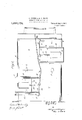
- FIG. 1 is a side elevation of a dump cart embodying our invention, and having the openings in its top in the form of hop-.
- Fig. "2 is a top plan view of the same;
- Fig. 3 is a front end elevation of a portion of the cart showing the hopper openings and the man ner of hanging the refuse can on the wagon in accordance with ourinvention;
- Fig. 4 is a front endview of a partof the cart body showing the can swung into position bottom up over the hopper opening, with suitable lever mechanism for operating the covers of the hopper and can;
- Fig. 5 1s a front end view of a part'of the cart body showing the an bottom up over the hopper with the sliding covers withdrawn;
- Fig. 6 isa cross sectional view taken online m-w Fig.
- Fig. 7 is a small side elevation of the cart body showing the hinged part of the cover in one of its raised positions, with means for raising and securing the hinged portion in said position;
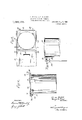
- Fig. 8 is a perspective. view of a novel form of refuse can used with our. cart showing the can with a sliding cover'partly withdrawn;
- Fig. 9 is a top plan view of the same show- .ing the'cover entirely withdrawn; Fig. 10
- Fig. 11 is an elevation of the can with the cover in the closed position
- Fig. 12 is a detail
- Figs. 1. and 2 1 is the body of a dump cart pivoted at 2 on a frame 3 which is supportedon wheels 4.
- the body of the cart is scoop shape having an inclined rear floor 5.
- the body is provided with an arched top 6 the rear portion 7 of which is hinged to the front portion by hinges 8, 8, so that itmay be swung out of position when the wagon is dumped.
- the cart shown is provided with two hoppers 9, 9, one on the right-hand side of the front portion 6 of the cart top, and the other on the left-hand side of the hinged portion 7.
- Each hopper is provided with a sliding cover 10 which slides back and forth in slideways 11 formed on top of the side walls of the hoppers (Figs. 2 and 6).
- any suitable mechanism may be utilized to move the cover back and forth in its slideway, such as a lever 12 pivoted to the side of the cart 13 and connected at its upper end through link 14 and crank 15 to a'stub shaft 16 mounted at the rear of the hopper and on which is rigidly secured a rodor lever 17the upper end ofvwhich passes through an opening in a horizontal rod 18 secured at the rear end of the cover 10.
- the garbage cans used in connection with the cart for collecting garbage or refuse form no part of this invention, and the same will be the subject matter of a separate the sheet metal top 19 are bent up to form slideways 21, 21 in which a sliding cover 22 moves back and forth to open and close the can.
- the front end of the sheet metal top is bent up to form a flange 23 for limiting the forward movement of the cover 22; while strips or tongues extending from the rear of the sheet metal top are bent up to .form hooks or hangers 24, and in these books horizontal straps 25 are secured.
- slideways 27 serve to aline the cover 22 with the slideways 21.
- the horizontal flanges on the slideways 27 are adapted to be engaged by a strip 28 secured to the front'end of the cover 22 to limit the rearward movement of the latter when it is drawn entirely out of the slideways 21, in which position the cover may be swung down in a vertical position as shown in Fig. 9.
- Each of the covers 22 is further provided with a suitable projection 29 for engaging a corresponding groove or recess 30 formed on the cover 10 of the hopper, so that when the can is swung bottom up over the hopper, the projection 29 will register with and engage in the groove 30, thus locking the sliding cover of the can with the sliding cover of the hopper, so that when the lever 12 is operated to move the sliding cover 11, the can cover 22 will slide with it, thus simultaneously uncovering the can and the hopper to permit the contents of the former to fall through the hopper into the body of the cart, after which the lever 12 may be operated to simultaneously close the can and hopper.
- each hopper is provided with one or more straps or guides 31, 31, in which a can carriage or supporting frame 33 slides back and forth.
- the carriage in the present instance is formed from a wrought iron bar, and comprises a front piece 34 substantially the width of the hopper, and side pieces 35, 35 which extend through the straps 31, 31.
- a suitable leaf spring 36 Upon the side of the hopper is secured a suitable leaf spring 36, the end of which is inseam bent in position to engage a notch 37 formed in one of the side pieces of the carriage, to hold the carriage in its raised position inside of the plane of the'wheel.
- the front end of the carriage 34 is reduced and made round in cross section at points 38, 38 to form a suitable supporting pivot for hooks 39, 39 on the garbage cans.
- a suitable guard piece 40 which, in the present form of the invention, consistsof a piece of sheet metal bent L-shaped and secured to the rear of the front piece 34 of the, carriage.
- any suitable device such as a latch 42 pivoted at the rear end of the hopper and engaging a pin or projection 43 on the can.
- the latch is provided with a handle 56 extending down to the side of the cart, by means of which the driver, when the can has been emptied, may
- the head of the latch is inclined and so positioned with respect to the projection 43 on the can that when the can is swung bottom up over the receptacle, the projection 43 will engage the inclined head of the latch and snap into position under the latch.
- a dog 48 pivotally mounted at the front end of the wagon on a suitable bracket 19; and adjacent this dog is pivoted a latch 50 having a handle 51.
- the latch 50 is provided with a spring 52 which normally holds the latch in the position shown in Fig. 7 against a stop 53, in which position the latch 50, by means of spring 52, presses against the toe of the dog 48 and holds it in position to engage a ring 54 in the chain 47.
- the driver takes hold of the handle 51 and moves it to the left against the pressure spring 52 thus rotating the latch on its pivot below the toe of the dog 48, and allowing the dog toswing about its pivot and release the chain!
- the sliding covers will be moved back in position to close the mouth of the hopper and the garbage can, after which lever 56 on the left ofthehopper may be moved to swing the latch 42 on its pivot to release the garbage can, whereupon the driver may swing the garbage can back into the position shown in Fig. 3,. and remove the same from the wagon.
- the driver takes hold of the chain 47 and pulls the same forward, swinging the lever 45 up into a vertical position, and raising the rear hinged portion 7 up into the position shown in Fig. 7 ,.in which position it is held by slipping ring 54 over the dog 48.
- a frame, a covered body pivoted on the frame arear cover portion hinged on the body, a connection from the hinged portion to the front of the cart for raising said portion, a dog pivoted at the front of the Wagon and cooperating with said connection to support the hinged portion, and a spring pressed latch holding the dog in its supporting position.
- a frame In a refuse cart, a frame, a covered body pivoted on the frame, a rear cover portion hinged on the body, a flexible connection from the hinged portion to the front of the cart for raising said cover portion, a dog pivoted at the front of the cart and engaging said flexible connection to support said hinged portion, a spring pressed latch engaging the 'dog and holding it in its support ing position, a-stop for the latch, a handle for moving the latch to release the dog, and a spring operating to snap I the dog into latching engagement with the latch when the flexible connection is released.
- a frame a covered body pivoted on the frame, a rear cover portion hinged on the body, a bracket secured to said hinged portion, a lever pivoted to the bracket, a connection from the lever to the front of the cart for raising said hinged cover, a dog pivoted at the front of the wagon and coiiperati'ng with said connection to support the hinged cover, and a spring pressed latch holding the dog in its supporting position.
- a frame a covered body pivoted on the frame, a rear cover portion hinged on the body, a vertical bracket, a lever pivoted at the rear of the bracket and having a part extending rearward there- 1:1 0
- a refuse cart the combination of a bin having one or more openings therein, a refuse can-supporting carriage mounted on said bin adjacent an opening and adapted to receive a refuse can and move in and out transversely of said bin therewith.
- a refuse cart the combination of a bin having one or more openings in its top, a refuse can supporting I carriage slidably mounted on the bin adjacent an opening and adapted to receive a refuse can and move in and out transversely of said bin therewith, and means for holding the carriage in its inward position adjacentthe opening.
- a refuse-can-supporting carriage comprising front and side pieces, and means on the side walls of the hopper slidably supporting the side pieces of the carriage whereby the carriage may be moved in and out toward and away from the hopper.
- a refuse cart the combination of a bin having one or more openings in its top in the form of hoppers, a refuse-can having supporting hooks adjacent its top, a supporting carriage for the can comprising front and side pieces, the front piece having pivot portions provided thereon on which the can hooks engage, a retaining guard on the carriage for the supporting hooks, and means on the side walls of the hopper slidably sup-' porting the side pieces of the carriage,
- a refuse cart in a refuse cart, the combination of a bin having one or more openings in its top in the form of hoppers, a refuse can having supporting hooks adjacent its top, a supporting carriage for the can comprising 11.
- a refuse cart the combination of a bin havingone or more openings in its top, a refuse can having supporting hooks adjacent its top, a supporting carriage for the can comprising front and side pieces, a retaining guard on the carriage for the supporting hooks, and means on the bin slidably supporting the side pieces of the carriage.
- a frame In a refuse cart, a frame, a covered body pivoted ontheframe, a rear cover portion hinged on the body to swing forward, an upright lever secured to the hinged cover by means of which the cover is raised in dumping.
- a frame In a refuse cart, a frame, a covered body pivoted on the frame, a rear cover portion hinged on the body to swing for ward, a vertical lever secured to the hinged cover adjacent its hinged end by means of which the driver may raise the hinged portion in dumping.
- a refuse cart a frame, a covered body pivoted on the frame, a rear cover portion hinged on the body to swing for ward, a hinged upright lever secured to the hinged cover by means of which the driver may raise the cover in dumping.
Description
0. PUTZEL & G. B. MARX.
GARBAGE OR REFUSE VEHICLE.
APPLICATION FILED AUG. 24,1910. 1,069,174, Patented Aug. 5, 1913.
INVENTORS 0. PUTZEL & G-QB. MARX.
GARBAGE 0R REFUSE VEHICLE.
APPLICATION FILED AUG. 24, 1910.
5 SHEETSSHEET 2.
WITNESSES: INVENTOR a In . ATTORNEY.
Patented Aug. 5, 1913.
G. PUTZEL & G. B. MARX.
GARBAGE 0R REFUSE VEHICLE.
APPLICATION FILED AUG. 24, 1910.
Patented Aug. 5, 1913.
5 SHEETSSHEET 3.
G. PUTZEL & G. B. MARX.
GARBAGE 0R REFUSE VEHICLE. APPLICATION FILED AUG. 24, 1910.
Patented Aug. 5, 1913.
5 SHEETS-SHEET 4 WITNESSES:
- ATTORN Y6.
G. PUTZBL & G. B. MARX.
GARBAGE OR REFUSE VEHICLE.
APPLICATION FILED AUG. 24, 1910.
Patented Aug. 5, 1913.
5 SHEETSSHEET 5.
INVENTbR s IINITED STATES PATENT OFFICE.
CHAR LES PUTZEL AND GEORGE B. MARX, OF NEW YORK, N. Y.
GARBAGE OR REFUSE VEHICLE.
Specification of Letters Patent.
Patented Aug. 5, 1913.
Application filed August 24, 1910. Serial No. 578,754.
and GEORGE B. MARX, both citizens of the United States, and residents of the city of New York, borough of Manhattan, county and State of New York, have invented certain new and useful Improvements in Garbage or Refuse Vehicles, of which the following is a specification.
Our; invention relates to garbage or refuse vehicles, and more particularly to suchvehicles having a closed body provided with suitable openings having removable covers,1througl1 which openings refuse cansmay be emptied into the wagon and removed in sucl1 manner as to prevent the escape of dust or obnoxious odors.
One of the objects of our invention is to provide a simple and durable vehicle of the above character which maybe readily loaded and dumped.
Another object of the invention is to pro vide means whereby the refuse cans may be conveniently hung on the vehicle. clear of thewheels, from which position'they may be swung bottom up over the openings. in the top of the vehicle body.
Another object of the invention is to provide a hinge. between parts of the body cover, and a novel form of operating mechanism for swinging the hinged portion out of position when the vehicle is being dumped.
' Our invention will best be understood from the following description taken in connection with the accompanying drawings showing the preferred embodiment of our invention, in which a Figure 1 is a side elevation of a dump cart embodying our invention, and having the openings in its top in the form of hop-.
pers, the body of the cart being shown in dotted lines in its dumped position; Fig. "2 is a top plan view of the same; Fig. 3 is a front end elevation of a portion of the cart showing the hopper openings and the man ner of hanging the refuse can on the wagon in accordance with ourinvention; Fig. 4 is a front endview of a partof the cart body showing the can swung into position bottom up over the hopper opening, with suitable lever mechanism for operating the covers of the hopper and can; Fig. 5 1s a front end view of a part'of the cart body showing the an bottom up over the hopper with the sliding covers withdrawn; Fig. 6 isa cross sectional view taken online m-w Fig. 5, with part of the can broken away and looking in the direction of the arrow; Fig. 7 is a small side elevation of the cart body showing the hinged part of the cover in one of its raised positions, with means for raising and securing the hinged portion in said position; Fig. 8 is a perspective. view of a novel form of refuse can used with our. cart showing the can with a sliding cover'partly withdrawn;
Fig. 9 is a top plan view of the same show- .ing the'cover entirely withdrawn; Fig. 10
is an elevation of the can showing the cover swung back on its hinge after being withdrawn; Fig. 11 is an elevation of the can with the cover in the closed position; and Fig. 12 is a detail,
Referring to-the drawings, Figs. 1. and 2: 1 is the body of a dump cart pivoted at 2 on a frame 3 which is supportedon wheels 4. The body of the cart is scoop shape having an inclined rear floor 5. The body is provided with an arched top 6 the rear portion 7 of which is hinged to the front portion by hinges 8, 8, so that itmay be swung out of position when the wagon is dumped. The cart shown is provided with two hoppers 9, 9, one on the right-hand side of the front portion 6 of the cart top, and the other on the left-hand side of the hinged portion 7. Each hopper is provided with a sliding cover 10 which slides back and forth in slideways 11 formed on top of the side walls of the hoppers (Figs. 2 and 6). Any suitable mechanism may be utilized to move the cover back and forth in its slideway, such as a lever 12 pivoted to the side of the cart 13 and connected at its upper end through link 14 and crank 15 to a'stub shaft 16 mounted at the rear of the hopper and on which is rigidly secured a rodor lever 17the upper end ofvwhich passes through an opening in a horizontal rod 18 secured at the rear end of the cover 10.
The garbage cans used in connection with the cart for collecting garbage or refuse form no part of this invention, and the same will be the subject matter of a separate the sheet metal top 19 are bent up to form slideways 21, 21 in which a sliding cover 22 moves back and forth to open and close the can. The front end of the sheet metal top is bent up to form a flange 23 for limiting the forward movement of the cover 22; while strips or tongues extending from the rear of the sheet metal top are bent up to .form hooks or hangers 24, and in these books horizontal straps 25 are secured. To the outer end of each strap 25 is pivotally mounted a second strap 26 the outer end of which is in the form of a-slideway 27 constructed to be in alinement with the slideway 21 when the cover 22 is in its horizontal position. These slideways 27 serve to aline the cover 22 with the slideways 21. The horizontal flanges on the slideways 27 are adapted to be engaged by a strip 28 secured to the front'end of the cover 22 to limit the rearward movement of the latter when it is drawn entirely out of the slideways 21, in which position the cover may be swung down in a vertical position as shown in Fig. 9. Each of the covers 22 is further provided with a suitable projection 29 for engaging a corresponding groove or recess 30 formed on the cover 10 of the hopper, so that when the can is swung bottom up over the hopper, the projection 29 will register with and engage in the groove 30, thus locking the sliding cover of the can with the sliding cover of the hopper, so that when the lever 12 is operated to move the sliding cover 11, the can cover 22 will slide with it, thus simultaneously uncovering the can and the hopper to permit the contents of the former to fall through the hopper into the body of the cart, after which the lever 12 may be operated to simultaneously close the can and hopper.
Due to the fact that unless the side of the body of the cart projected over the wheels, the latterwould interfere with the ready dumping of the garbage can into the hopper, it has heretofore been found advisable,,
if not necessary, to use low wheels on wagons and carts of the general character to which this invention relates, since, if high wheels were used, the hopper would be too high to be conveniently reached with the garbage can. Tn order to be able to utilize high wheels on wagons of the general character above described, we have provided the following means by which the above described apparatus may be readily and conveniently used on high wheeled wagons, as shown in the accompanying drawings. The side of each hopper is provided with one or more straps or guides 31, 31, in which a can carriage or supporting frame 33 slides back and forth. The carriage in the present instance, is formed from a wrought iron bar, and comprises a front piece 34 substantially the width of the hopper, and side pieces 35, 35 which extend through the straps 31, 31. Upon the side of the hopper is secured a suitable leaf spring 36, the end of which is inseam bent in position to engage a notch 37 formed in one of the side pieces of the carriage, to hold the carriage in its raised position inside of the plane of the'wheel. The front end of the carriage 34 is reduced and made round in cross section at points 38, 38 to form a suitable supporting pivot for hooks 39, 39 on the garbage cans.
In order to prevent the books 39, 39 from slipping off of the front piece 3 1 of the carriage when the can is being swung up in position over the hopper, we provide a suitable guard piece 40 which, in the present form of the invention, consistsof a piece of sheet metal bent L-shaped and secured to the rear of the front piece 34 of the, carriage. When the garbage can is swung bottom up over the hopper opening, as shown in Fig. 6, the slideways 21 of the can rest firmly on top of the slideways 11 of the hopper mouth and between vertical flanges 41 secured on top of the slideways 11.
In order to hold the garbage can firmly down upon the hopper, We use any suitable device such as a latch 42 pivoted at the rear end of the hopper and engaging a pin or projection 43 on the can. The latch is provided with a handle 56 extending down to the side of the cart, by means of which the driver, when the can has been emptied, may
release the latch. The head of the latch is inclined and so positioned with respect to the projection 43 on the can that when the can is swung bottom up over the receptacle, the projection 43 will engage the inclined head of the latch and snap into position under the latch.
in order to dump the contents of the wagon after it has been loaded, it is necessary to raise the hinged portion 7 of the top of the body, and to permit the. driver to raise and lower the hinged portion without leaving his seat, we have provided the following apparatus: At the hinged end of the cover portion 7, we provide a suitable standard or bracket 44 to which is pivoted a bent lever 45 having a portion 4-6 bent substantially at right angles to the general direction of the lever; and from this lever a chain 47 passes to the front of the wagon, where it is permanently secured, the chain being of sufiicient length to permit the hinged portion to be closed and allow the lever to drop down in the position shown in lFig. 1. ln order to support the hinged portion 7 in one or more of its raised posi-. tions, we provide a dog 48 pivotally mounted at the front end of the wagon on a suitable bracket 19; and adjacent this dog is pivoted a latch 50 having a handle 51. The latch 50 is provided with a spring 52 which normally holds the latch in the position shown in Fig. 7 against a stop 53, in which position the latch 50, by means of spring 52, presses against the toe of the dog 48 and holds it in position to engage a ring 54 in the chain 47. Whenjt is desired to drop the hinged portion 7, the driver takes hold of the handle 51 and moves it to the left against the pressure spring 52 thus rotating the latch on its pivot below the toe of the dog 48, and allowing the dog toswing about its pivot and release the chain! As soon as the dog 48' is relieved of the weight of the hinged portion 7, a suitable spring 55 throws the head of the dog 48 forward, at which time the heel of the dog snaps back into position past the head of latch 50, where upon the latch again engages the toe of the dog and holds the latter in position to again receive the chain for supporting the hinged portion 7.' 1 v The operation of the embodiment of our invention above described is as follows: The garbage can to be emptied is lifted in the position shown in Fig. 3, where'it is suspended, bymeans of the hooks 39, from the front bar 34 of the carriage 33. When the can is in this position, the driver takes hold of it and swings it up in the position shown,
in Fig. 4, during which movement the car riage 33 is forced inward to the position shown in Fig. 4, in which position it is held in place by the spring 36. The cover .of the garbage can is now lying parallel with and directly over the sliding cover on the hopper, in which position the projection 29 on the cover of the can engages the groove 30 on the cover 10 of the hopper. The handle 12 is now pulled outward from the side of the wagon, causing the rod 17 Y to swing upward on its shaft 16, as shown in Fig. 5, withdrawing the sliding cover 10 and with it the garbage cover '22, whereupon the contents of the can will fall into the-wagon. If the handle 12 is now moved in toward the wagon, the sliding covers will be moved back in position to close the mouth of the hopper and the garbage can, after which lever 56 on the left ofthehopper may be moved to swing the latch 42 on its pivot to release the garbage can, whereupon the driver may swing the garbage can back into the position shown in Fig. 3,. and remove the same from the wagon. In orderto dump thewagon, the driver takes hold of the chain 47 and pulls the same forward, swinging the lever 45 up into a vertical position, and raising the rear hinged portion 7 up into the position shown in Fig. 7 ,.in which position it is held by slipping ring 54 over the dog 48. After the wagon is dumped, the driver, by moving handle 51 against the spring 52, releases the dog 48 and allows the hinged portion to drop back in its closed position, whereupon the pivoted lever 45 drops back in the position shown in Fig. 1, where it is out of the way of projecting objects and the operatin parts of the wagon. By constructing the lever 45 in the manner shown, we
are enabled to get a long leveragein raising the hinged portion, and yet avoid the disadvantages of the lever projecting up in the air at all times when not in use. 1 Llk8-1 wise, the bent portion 46 of the lever-holds by the. chain.
We have shown and described our inven' tion in the form now best known to us, .but obviously various changes and modifications may be made therein, and We do not wish."
to be understood as limiting ourselves to any particular arrangement or construction other than asset forth in .the appended claims.
Having thus descrlbed our invention, what 1 we claim as new and desire 'to secure by Letters Patent, is:
1. In a refuse cart, a frame, a covered body pivoted on the frame,a rear cover portion hinged on the body, a connection from the hinged portion to the front of the cart for raising said portion, a device engaging said connection to support the hinged portion, and a spring pressed handle for'releasing said device to drop the hinged portion. 2. Ina refuse cart, a frame, a covered body pivoted on the frame, arear cover portion hinged on the body, a connection from the hinged portion to the front of the cart for raising said portion, a dog pivoted at the front of the Wagon and cooperating with said connection to support the hinged portion, and a spring pressed latch holding the dog in its supporting position.
3. In a refuse cart, a frame, a covered body pivoted on the frame, a rear cover portion hinged on the body, a flexible connection from the hinged portion to the front of the cart for raising said cover portion, a dog pivoted at the front of the cart and engaging said flexible connection to support said hinged portion, a spring pressed latch engaging the 'dog and holding it in its support ing position, a-stop for the latch, a handle for moving the latch to release the dog, and a spring operating to snap I the dog into latching engagement with the latch when the flexible connection is released. v
4. In a refuse cart, a frame, a covered body pivoted on the frame, a rear cover portion hinged on the body, a bracket secured to said hinged portion, a lever pivoted to the bracket, a connection from the lever to the front of the cart for raising said hinged cover, a dog pivoted at the front of the wagon and coiiperati'ng with said connection to support the hinged cover, and a spring pressed latch holding the dog in its supporting position.
5. In a refuse cart, a frame, a covered body pivoted on the frame, a rear cover portion hinged on the body, a vertical bracket, a lever pivoted at the rear of the bracket and having a part extending rearward there- 1:1 0
.. 0 1t in position so that it may be readilyraised j from whereby the lever, when released, will gravitate from its raised position, a flexible connection from said lever to the front of the cart for raising said hinged cover, a dog pivoted at the front of the wagon and engaging the flexible connection to support said hinged cover, and a spring pressed latch holding the dog in its supporting position.
(3. In a refuse cart, the combination of a bin having one or more openings therein, a refuse can-supporting carriage mounted on said bin adjacent an opening and adapted to receive a refuse can and move in and out transversely of said bin therewith.
7. ln a refuse cart, the combination of a bin having one or more openings in its top, a refuse can supporting I carriage slidably mounted on the bin adjacent an opening and adapted to receive a refuse can and move in and out transversely of said bin therewith, and means for holding the carriage in its inward position adjacentthe opening.
8. in a refuse cart the combination of a bin having one or more openings in its top in the form of hoppers, a refuse-can-supporting carriage comprising front and side pieces, and means on the side walls of the hopper slidably supporting the side pieces of the carriage whereby the carriage may be moved in and out toward and away from the hopper.
9. ln a refuse cart, the combination of a bin having one or more openings in its top in the form of hoppers, a refuse-can having supporting hooks adjacent its top, a supporting carriage for the can comprising front and side pieces, the front piece having pivot portions provided thereon on which the can hooks engage, a retaining guard on the carriage for the supporting hooks, and means on the side walls of the hopper slidably sup-' porting the side pieces of the carriage,
i0. in a refuse cart, the combination of a bin having one or more openings in its top in the form of hoppers, a refuse can having supporting hooks adjacent its top, a supporting carriage for the can comprising 11. In a refuse cart, the combination of a bin havingone or more openings in its top, a refuse can having supporting hooks adjacent its top, a supporting carriage for the can comprising front and side pieces, a retaining guard on the carriage for the supporting hooks, and means on the bin slidably supporting the side pieces of the carriage.
12. In a refuse cart, a frame, a covered body pivoted ontheframe, a rear cover portion hinged on the body to swing forward, an upright lever secured to the hinged cover by means of which the cover is raised in dumping.
13. In a refuse cart, a frame, a covered body pivoted on the frame, a rear cover portion hinged on the body to swing for ward, a vertical lever secured to the hinged cover adjacent its hinged end by means of which the driver may raise the hinged portion in dumping.
14.. lln a refuse cart, a frame, a covered body pivoted on the frame, a rear cover portion hinged on the body to swing for ward, a hinged upright lever secured to the hinged cover by means of which the driver may raise the cover in dumping.
in testimony whereof, we have signed our names to this specification, in the presence of two subscribing witnesses.
CHARLES PUTZEL. .GEURGE B. MARK.
Priority Applications (1)
| Application Number | Priority Date | Filing Date | Title |
|---|---|---|---|
| US57875410A US1069174A (en) | 1910-08-24 | 1910-08-24 | Garbage or refuse vehicle. |
Applications Claiming Priority (1)
| Application Number | Priority Date | Filing Date | Title |
|---|---|---|---|
| US57875410A US1069174A (en) | 1910-08-24 | 1910-08-24 | Garbage or refuse vehicle. |
Publications (1)
| Publication Number | Publication Date |
|---|---|
| US1069174A true US1069174A (en) | 1913-08-05 |
Family
ID=3137412
Family Applications (1)
| Application Number | Title | Priority Date | Filing Date |
|---|---|---|---|
| US57875410A Expired - Lifetime US1069174A (en) | 1910-08-24 | 1910-08-24 | Garbage or refuse vehicle. |
Country Status (1)
| Country | Link |
|---|---|
| US (1) | US1069174A (en) |
Cited By (1)
| Publication number | Priority date | Publication date | Assignee | Title |
|---|---|---|---|---|
| US2652946A (en) * | 1950-03-20 | 1953-09-22 | Guy M Beatty | Cleanout gate valve |
-
1910
- 1910-08-24 US US57875410A patent/US1069174A/en not_active Expired - Lifetime
Cited By (1)
| Publication number | Priority date | Publication date | Assignee | Title |
|---|---|---|---|---|
| US2652946A (en) * | 1950-03-20 | 1953-09-22 | Guy M Beatty | Cleanout gate valve |
Similar Documents
| Publication | Publication Date | Title |
|---|---|---|
| US5011036A (en) | Front loading, foot operated refuse bin | |
| US2949199A (en) | Containers for self-loading vehicles | |
| US4405278A (en) | Self-emptying dump box | |
| US3032216A (en) | Container dumping attachment for refuse trucks | |
| US2895238A (en) | Dump scoop | |
| US430355A (en) | Bag filler and holder | |
| US1069174A (en) | Garbage or refuse vehicle. | |
| US1776034A (en) | Dust cart | |
| US2471874A (en) | Dump car | |
| US2797832A (en) | Hand trucks | |
| US1180292A (en) | Combined refuse vehicle-compartment and refuse-receptacle. | |
| US1026465A (en) | Refuse-wagon. | |
| US576727A (en) | The nor | |
| US1560108A (en) | Car and unloader | |
| US415958A (en) | clark | |
| US1106523A (en) | Dumping-wagon or analogous container. | |
| US1111052A (en) | Refuse-vehicle. | |
| US2570244A (en) | Dump truck scraper | |
| US1030884A (en) | Dumping-wagon. | |
| US1292670A (en) | Cart and loader. | |
| US570060A (en) | The morris peters co | |
| US465328A (en) | smith | |
| JPS5845375B2 (en) | Tailgate opening/closing device for container handling vehicles | |
| US2116311A (en) | Garbage receptacle | |
| US844891A (en) | Dumping-vehicle. |