US1069173A - Machine for making lasts. - Google Patents
Machine for making lasts. Download PDFInfo
- Publication number
- US1069173A US1069173A US7208101A US1901072081A US1069173A US 1069173 A US1069173 A US 1069173A US 7208101 A US7208101 A US 7208101A US 1901072081 A US1901072081 A US 1901072081A US 1069173 A US1069173 A US 1069173A
- Authority
- US
- United States
- Prior art keywords
- last
- jaw
- clamp
- lasts
- block
- Prior art date
- Legal status (The legal status is an assumption and is not a legal conclusion. Google has not performed a legal analysis and makes no representation as to the accuracy of the status listed.)
- Expired - Lifetime
Links
Images


Classifications
-
- B—PERFORMING OPERATIONS; TRANSPORTING
- B27—WORKING OR PRESERVING WOOD OR SIMILAR MATERIAL; NAILING OR STAPLING MACHINES IN GENERAL
- B27M—WORKING OF WOOD NOT PROVIDED FOR IN SUBCLASSES B27B - B27L; MANUFACTURE OF SPECIFIC WOODEN ARTICLES
- B27M3/00—Manufacture or reconditioning of specific semi-finished or finished articles
- B27M3/20—Manufacture or reconditioning of specific semi-finished or finished articles of lasts; of shoes, e.g. sabots; of parts of shoes, e.g. heels
Definitions
- lever is pointed, and a scale is formed on the heel rest to 'indicate the position of the lever.
- An arm (Z7 is pivoted on the heel rest beneath the lever, and is engaged by a flat spring which co-acts with flat surfaces upon the arm to hold the arm either in a vertical position, where the rearward end of 'the lever is 'elevated and thegage held out of contact with the last, or in an inclined posi tion, where the lever is free to move.
- the slide d has a vertical apron d8 whose lower edge is guided in a guideway d on the bracket l).
- U on the apron are horizontal guides 1 in Y'which is mounted a slide I.
- the latter slide is connected by a dle is swiveled to a yoke 3, to which a link- 4 is pivoted, the lower end of the link being pivoted to a treadle 5.
- An arm i projects' from the back plate B, and supports a pin which engages a slot in a levert that is pivoted on the apron d8.
- the forward end of thelever is provided 'with a lug 8, which 'is adapted to rest upon the upper surface of an arm 9 on the yoke and to prevent the rising of the yoke and routing tool except when such lug is opposite a slot 1 in the yoke when the latter is free to rise and carry the routing tool.
- a lever 11 is pivoted on the ⁇ apron and has a slot which is engaged by a pin 12 that .is supported by an arm 13, the latter being fastened to the table.
- a lever 2' is pivoted on an arm z'l* projecting from the apron and one end thereof 'is adapted to be acted upon by the upper flat surface of an arm il on the yoke.
- the opposite end ofthe lever is connected to a link 19 whose upper end is pivoted to a rod z' which is mounted in a socket in a thrust arm 18.
- the rod 11 has a cross pin which projects through slots in the thrust arm, and' which is normally held at the upper end of said slots by a spring 20 interposed between the ends of such pin and a flange on the thrust arm.
- the thrust arm' passes through a bearing in the slide d, and is bent over to beer upon the upper surface of the last.
- a horizontal circular saw is mounted in such position,
- vA guide a extends along the tableA in front of the row of brackets, and a seco-nd guide a is secured to the table perpendicular to the guide a at the left end thereof.
- a shaft L is mounted inhorizontal bearings on the table, and guides Z and Z are-secured to the v table perpendicularly to the said shaft.
- a saw Z2 is mounted upon the shaft L, and such saw is provided with teeth upon its outer periphery, having their cutting edges parallel to the shaft, and also with teeth projecting laterally from the face of the saw, and having their cutting edges per pendicular to the said shaft.
- a lug Z3 vis formed on-a plate which is adjustably fas tened y,on the guide Z by a screw passing through a slot in the said plate.
- To the .right of the shaft L,'a'shaft M is mounted in bearings on the table, that are. slightly inlclined to. the horizontal, and such shaft carries a circular saw m.
- a guide m perpendicular to the shaft is secured upon the,
- a clamp N is provided for holding the last.
- the frame of such clamp consists ,of a, rectangular base, having sides rising vertically therefrom, the sides being connected by a cross-piece at thetop.
- the sides are provided with vertical guides, on which are mounted upper and loper heads n* and am, respectively that are provided with clamp jaws.
- the upper head is reciprocated by means of a hand screw, that is journaled" therein.
- the lower head is adjusted vertically ⁇ by means of a pair of wedges n whichl are received in inclined slots in the underside of the lower head, that are connected ⁇ by a cross piecem?, and which are adjusted by means of a hand screw as that is journaled in a lug fastened to the base, and is threaded intothe crossv piece n2.
- a lock nut n4 is threaded on the screw n3.
- the upper holder a5 is pivoted between lugs that are screwed to the upper head.
- Such holder is preferably curved' rearward and downwardand is provided with a V-shaped notch vthat is adapted to engage the comb of the last.
- a screw n is threaded into the ga e and is adapted to bear upon a lug 'n.7 ormed 4in one of the bearings of the gage to limit the downward movement thereof.
- clamp jaws arc separated, the last is placed between them, and the clamp is placed in the angle between the guides a and a.
- the heel of the last is'held firmly on the heel rest and in engagement with the forked spring (Z4.
- the arm d? is drawn down to leave the bottom gage (ZB free to come in Contact with the lower portion of the instep.
- The'wedges yn. and lff-are then adjusted until the lever d points to the marl; on its scale which indicates that the instep is at the proper level to correctly position 'the cuts'in the fore-part and forward portion of the heelpart of the last.
- The-last is tipped laterally until it has the proper vertical position.
- the side gage n is then moved outward to contact with the last by moving the wedge n downward, and is then clamped by the thumb screw in the holder n. The hand screw of the clamp is then turned, thus forcing the upper gage and the seat for the anvil heel sea-t of the last.
- the bottom orv instep gage will thus be seen to be usedonly in positioning the wedges correctly for the first last of a series of lasts to be cut, and the wedges can then be afterward properly adjusted for the other lasts of the series, by the use of the now properlyadjusted scale plates.
- the last being now iirmly and properly held in the clamp and the heel rest, the treadle is ing the routing tool to enter the last atthe forward portion of the intended slot in the heel part.
- the hand lever is then drawn forward, causing the routing tool to pass rearward, the level of the routingy tool being determined by the level of the lug 8 on the levert'7 coming in contact with the upper surface of the arm is. on the yoke.
- the routing tool thus passes rearward until the depressed, causlug on said lever is opposite the slotor opening 1 in the said arm, when the routing tool can be forced upward by a further depressionof the treadle, thus causing the routing tool to bore the hole O for the jack pin socket, and causing the countersink to countersink the lower end thereof.
- the routingV tool rises, the lever 15 is moved by the arm il to yieldingly bear down the thrust arm upon the upper side of the last,
- the clamp is now moved to the right along the guide a past the saw e, and the latter cuts away the material A,as indicated by the lines o and oto form the The clamp, upon continuing the movement in the same direction, vcarries the last past the saw 7 and the saw-cut 02 forming the beveled forward face of the heel part is4 made. Further movement of the clamp along the guide a causes the saw g to sever the now-completed heel part from the fore part as indicated by the lines o3. The clamp is then moved along the guide Z carrying the having upper and' lower cylindrical surfaces concentric with a point above said block, the surfaces between which said Jaw moves being curved to correspond to said Jaw, and
- a concave cylindricali seat formed in said base, a jaw mounted in said seat and having upper and ylower cylindrical surfaces concentric with a point above said block, and ablock having a convex cylindrical surface adapted to bear upon the upper side of said jaw, said block being adapted to support a last.
- a clamp forI a last consisting of a frame, aniupper clamping jaw, means on said frame for moving said jaw toward the base thereof, a concave cylindrical seat formed in said base, a jaw mounted in said seat and having upper and lower cylindrical surfaces concentric with a point above said block, a block having a convex cylindrical surface adapted to bear 'upon the upper side y of said jaw, said block being adapted to support a last, and a spring tending to move said lower jaw toward the position of the last.
- a tool for making lasts the combination of a frame, a clamp jaw and means for forcing such jaw toward the last, said jaw having convex points or projections formed thereon by which it can adapt itself to Athe irregular surface of the last, 'said jaw being slidably mounted on said means for forci'.' g it toward the last to move in a directie i1 transverse to the clamping movement, whereby the jaw can rst adapt itself to the last and thenbe clamped in adjusted position as it is forced against the last- 13.
- a clamp jaw so shaped as to contact with the last at a plurality of spaced points, and means for'forcing such ⁇ jaw toward the object to be clamped, such jaw and said means having opposing surfaces which are disposed transversely to the direction of pressure of said means, such surfaces being capable of being brought into irm contact by said means, and gages for positioning the last on its support so arranged as to be unaffected by the clamping action, said clamping means accommodating themsleves to and i clamping the last in the position determined by said gages.
- a tool for making lasts the combination of a clamp jaw, a block having a connection with said jaw can tilt, a slide torwhich said, block is swiveled, a head on which such slide is mounted, and means for forcing such head by which the latter surfaces agreeing with toward Ythe object -to be clamped, such jaw and block, said block and slide, and such slide and said head having opposing surfaces disposed transversely to the line of pressure of suc-h forcing means, and said parts being capable of forcing such surfaces into firm contact with each other, Substanf tially als and for the purpose described.
- the combi nation of a heel rest a clamp for engaging phefore-.part of the last, guides for positionng the clamp and heel rest relative to each other, whereby the last can rst be adjusted in the heel rest and clamp and then secured in the clamp, and whereby the clamp can then be detached from the heel rest and used for presenting the last to the cutters.
- a clamp forlasts the combination of a frame, a support for the sole ofgthe last adjustably carried by said frame, a jaw above the last, said jaw being forked -at its' forward and rearward ends and having 'a' convex, upper surface, said forked ⁇ ends of said jaw being adapted to Contact witha last, at. spaced points upon opposite sides of the comb and toe portion, a block having a concave surface adapted to fit the upper I surface of said jaw, and means for forcingsaid block toward the last.
- a clamp for lasts the combination of a frame, a support for the last, upper and lower jaws having their surfaces most remote from the last conveXly curved on the arcs of circles whose centers are between the Jaws', said jaws having faces constructed and arranged to contact with and hold a last, supports for said. jaws having concave and adapted to engage said conveX surfaces, and means for forcing said jaws together.
- a clamp for lasts the combination of a frame, asupport for the sole of the last, said support being formed in two''aparts, a slideway formed between said parts and curved from a center above the support, a curved jaw seated in said slideway, and. means for forcingdhe last down upon'saiJL support.
- a clamp for lasts the ,combination of a. frame; a support for the sole of the last, a head movable up and down above 'the last., a block transverselyslidable upon said head, a block swiveled to said first-mentioned block, said last-mentioned block havin a concave lower surface, an upper jaw forked at its forward and rearward endsand hav ing a convex upper surface adapted tot said concave surface on said last-mentioned bloc means for loosely supporting said clamp Yrom said block, and means for forcing said head toward the last.
- a'base adapted to support a. last, gages for the heel, comb and side of the last, which gages are adapted to occupy fixed iso l nai-ily position the toot-shaped contour of g inseam positions relative to said base, clamping jaws, and means for moving said Ajaws against a last While positioned against said gages, said jaws and means being so con-v structed as to permit said jaws to automaticall y adji :t themselves to the last before being ⁇ clamped and to then cause them to be clamped.
- a clamp jaw and a head that are i laterallux7 immovaloln With relation to the obt iec to be clamped, and a second clamp jaw nterposed 7oetifecn and laterally movable with relation to id tirstementioned jaw and iidvhead, such irst-ineniioned jan' and said i wad being capable of movement toward 1 wh other to clamp them between such sec-- ond jaw, substantiall)Y and for the purpose described.
Description
E. J, PR'EDLE. MACHINE FOR MAXIM LASTS,
,APPLICATION FILED AUG. 14, 1G01.
E E. PRINDLE.- MACHINE FOR MAKING LASTS,
APPLICATION FILED AUG. 14, i901.
aented Aug. 5, 1913.
l0 SHEETS-*SHEET 2.
MAKING LASTS.
E FOR PPLCATlON FILED AUG. 14, 1991,
E J. PRINDLE. MACHINE ma mmm LASTS.
a Y r APPLICATION FILED AUG.14. 1901. L u 1 @@Qpfgg Patented Aug, 5, 1&3.
10 SHEETS-SHEET 5.
E. J. PRINDLE.
MACHINE FOR MAKING LASTS. APPLICATION FILED AUG 14. 1901.
ggggyyg, Patente Aug. 5, 1913.
10 SHEETS-SHEET 6,
MACHINE EUR MAKNG LASTS,
AEPLIGATIOH FILED man, 1vol.
10 SHEETSFSE instep of the last. lever is pointed, and a scale is formed on the heel rest to 'indicate the position of the lever. An arm (Z7 is pivoted on the heel rest beneath the lever, and is engaged by a flat spring which co-acts with flat surfaces upon the arm to hold the arm either in a vertical position, where the rearward end of 'the lever is 'elevated and thegage held out of contact with the last, or in an inclined posi tion, where the lever is free to move.
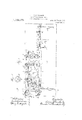
The slide d has a vertical apron d8 whose lower edge is guided in a guideway d on the bracket l). U on the apron are horizontal guides 1 in Y'which is mounted a slide I. The latter slide is connected by a dle is swiveled to a yoke 3, to which a link- 4 is pivoted, the lower end of the link being pivoted to a treadle 5. An arm i projects' from the back plate B, and supports a pin which engages a slot in a levert that is pivoted on the apron d8. The forward end of thelever is provided 'with a lug 8, which 'is adapted to rest upon the upper surface of an arm 9 on the yoke and to prevent the rising of the yoke and routing tool except when such lug is opposite a slot 1 in the yoke when the latter is free to rise and carry the routing tool. A lever 11 is pivoted on the` apron and has a slot which is engaged bya pin 12 that .is supported by an arm 13, the latter being fastened to the table. The
upper end of the said lever carries a set screw which is adapted to be struck by and to limit the forward movement of the slide I. The rearward movement of the said slide is limited by a set screw i on the apron cZS.
A lever 2' is pivoted on an arm z'l* projecting from the apron and one end thereof 'is adapted to be acted upon by the upper flat surface of an arm il on the yoke. The opposite end ofthe lever is connected to a link 19 whose upper end is pivoted to a rod z' which is mounted in a socket in a thrust arm 18. The rod 11 has a cross pin which projects through slots in the thrust arm, and' which is normally held at the upper end of said slots by a spring 20 interposed between the ends of such pin and a flange on the thrust arm. The thrust arm'passes through a bearing in the slide d, and is bent over to beer upon the upper surface of the last. On the slide e of the bracket E, a horizontal circular saw is mounted in such position,
The rearward end of the and is of such thickness as to cut away the material of the lastV to formthe anvil heel seat as the last is moved past such saw. On the slide f of the bracketF a circular saw f is mounted in a forwardly inclined position so as to form the sawpcut on the forward face of the heel partof the last. On the slide g of the bracket G is mounted a vertical circular saw g in position to sever the heel part from the fore-part of the last' and form the vertical surface of the forepart. vA guide a extends along the tableA in front of the row of brackets, and a seco-nd guide a is secured to the table perpendicular to the guide a at the left end thereof. Preferably, beyond the bracket G a shaft L is mounted inhorizontal bearings on the table, and guides Z and Z are-secured to the v table perpendicularly to the said shaft. A saw Z2 is mounted upon the shaft L, and such saw is provided with teeth upon its outer periphery, having their cutting edges parallel to the shaft, and also with teeth projecting laterally from the face of the saw, and having their cutting edges per pendicular to the said shaft. A lug Z3 vis formed on-a plate which is adjustably fas tened y,on the guide Z by a screw passing through a slot in the said plate. To the .right of the shaft L,'a'shaft M is mounted in bearings on the table, that are. slightly inlclined to. the horizontal, and such shaft carries a circular saw m. A guide m perpendicular to the shaft is secured upon the,
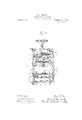
table. A clamp N is provided for holding the last. iThe frame of such clamp consists ,of a, rectangular base, having sides rising vertically therefrom, the sides being connected by a cross-piece at thetop. The sides are provided with vertical guides, on which are mounted upper and loper heads n* and am, respectively that are provided with clamp jaws. The upper head is reciprocated by means of a hand screw, that is journaled" therein. The lower head is adjusted vertically`by means of a pair of wedges n whichl are received in inclined slots in the underside of the lower head, that are connected` by a cross piecem?, and which are adjusted by means of a hand screw as that is journaled in a lug fastened to the base, and is threaded intothe crossv piece n2. A lock nut n4 is threaded on the screw n3. The upper holder a5 is pivoted between lugs that are screwed to the upper head. Such holder is preferably curved' rearward and downwardand is provided with a V-shaped notch vthat is adapted to engage the comb of the last. A screw n is threaded into the ga e and is adapted to bear upon a lug 'n.7 ormed 4in one of the bearings of the gage to limit the downward movement thereof. A-springn? coiled about a pin passing througlrears in thegag and eX- tending into the bearings, has one end bearing position, is capable of resolution. into (l) a tilting movement longitudinally of the last,
which movement is permittedL by the connection between the jaw and the block 71.22 consisting of the arc-shaped flanges 11,26 and the grooves 11,28; (2) an axial movement, which movement is permitted by the swiveling of the block w22 to the slide n2, and (3) a movement transversely of the last, which movement is permitted by the connection between such slide and the head n* consistblocks n.34 and the head uw.
ing of the plates on the slides and the grooves on the head. During such movement of the said head thelower clamp jaw ns1 which is normally thrust out of its recess by the spring a is forced by contact with the last back into the recess between the Further movement of the lower head causes the spring plate n to come against the sole oi' the last, preferably the ball thereof. The final tightening of the screwlorces the upper surface' of the upper clamp jaw into firm contact with the under surface of the block M2, thus locking such parts together, and preventing the screw, the spring plate w33 is bent by the sole of the lest, causing the lower clamp jaw tobe impinged upon by and firmly held between the arc-shaped seat in said head and the blocks n attached to such spring plate. The last has now been firmly clamped.
In the operation of my machine, the
! clamp jaws arc separated, the last is placed between them, and the clamp is placed in the angle between the guides a and a. The heel of the last is'held firmly on the heel rest and in engagement with the forked spring (Z4. The arm d? is drawn down to leave the bottom gage (ZB free to come in Contact with the lower portion of the instep. The'wedges yn. and lff-are then adjusted until the lever d points to the marl; on its scale which indicates that the instep is at the proper level to correctly position 'the cuts'in the fore-part and forward portion of the heelpart of the last. The-last is tipped laterally until it has the proper vertical position. The side gage n is then moved outward to contact with the last by moving the wedge n downward, and is then clamped by the thumb screw in the holder n. The hand screw of the clamp is then turned, thus forcing the upper gage and the seat for the anvil heel sea-t of the last.
down upon the comb of the last, and bringing the comb and the rear portion of the heel in a line through the center of the clamp, and causing the clamp jaws to firmly grasp the last. The scale plates for the side gage and for the pointers' on the wedges are then adjusted, so that the number corresponding to the length of the last is opposite the mark on the wedge of the side gage pointer on the wedge n", respectively. These scales, now having been properly positioned for one size of last, can be used to properly position the wedges n and the side gage n for other lasts ofthe same proportions, by merely adjusting the side gage wedge and the pointer on the wedge n to numbers on the scale plates corresponding to the length of the last. The bottom orv instep gage will thus be seen to be usedonly in positioning the wedges correctly for the first last of a series of lasts to be cut, and the wedges can then be afterward properly adjusted for the other lasts of the series, by the use of the now properlyadjusted scale plates. The last, being now iirmly and properly held in the clamp and the heel rest, the treadle is ing the routing tool to enter the last atthe forward portion of the intended slot in the heel part. The hand lever is then drawn forward, causing the routing tool to pass rearward, the level of the routingy tool being determined by the level of the lug 8 on the levert'7 coming in contact with the upper surface of the arm is. on the yoke. The routing tool thus passes rearward until the depressed, causlug on said lever is opposite the slotor opening 1 in the said arm, when the routing tool can be forced upward by a further depressionof the treadle, thus causing the routing tool to bore the hole O for the jack pin socket, and causing the countersink to countersink the lower end thereof. As the routingV tool rises, the lever 15 is moved by the arm il to yieldingly bear down the thrust arm upon the upper side of the last,
to counteract the tendency 'of the routingtool to raise the last.- At the same time the routing tool is passing rearward, the drill H is forced through the last laterally to form the hole for the pin which secures the hinge in the last. The clamp is now moved to the right along the guide a past the saw e, and the latter cuts away the material A,as indicated by the lines o and oto form the The clamp, upon continuing the movement in the same direction, vcarries the last past the saw 7 and the saw-cut 02 forming the beveled forward face of the heel part is4 made. Further movement of the clamp along the guide a causes the saw g to sever the now-completed heel part from the fore part as indicated by the lines o3. The clamp is then moved along the guide Z carrying the having upper and' lower cylindrical surfaces concentric with a point above said block, the surfaces between which said Jaw moves being curved to correspond to said Jaw, and
means for forcing the last upon said block,l
base thereof, a concave cylindricali seat formed in said base, a jaw mounted in said seat and having upper and ylower cylindrical surfaces concentric with a point above said block, and ablock having a convex cylindrical surface adapted to bear upon the upper side of said jaw, said block being adapted to support a last.
11. A clamp forI a last consisting of a frame, aniupper clamping jaw, means on said frame for moving said jaw toward the base thereof, a concave cylindrical seat formed in said base,a jaw mounted in said seat and having upper and lower cylindrical surfaces concentric with a point above said block, a block having a convex cylindrical surface adapted to bear 'upon the upper side y of said jaw, said block being adapted to support a last, and a spring tending to move said lower jaw toward the position of the last.
l2. In a tool for making lasts, the combination of a frame, a clamp jaw and means for forcing such jaw toward the last, said jaw having convex points or projections formed thereon by which it can adapt itself to Athe irregular surface of the last, 'said jaw being slidably mounted on said means for forci'.' g it toward the last to move in a directie i1 transverse to the clamping movement, whereby the jaw can rst adapt itself to the last and thenbe clamped in adjusted position as it is forced against the last- 13. In a tool for making lasts, the combinationof a clamp jaw so shaped as to contact with the last at a plurality of spaced points, and means for'forcing such` jaw toward the object to be clamped, such jaw and said means having opposing surfaces which are disposed transversely to the direction of pressure of said means, such surfaces being capable of being brought into irm contact by said means, and gages for positioning the last on its support so arranged as to be unaffected by the clamping action, said clamping means accommodating themsleves to and i clamping the last in the position determined by said gages.
14. I n a tool for making lasts, the combination of a clamp jaw, a block having a connection with said jaw can tilt, a slide torwhich said, block is swiveled, a head on which such slide is mounted, and means for forcing such head by which the latter surfaces agreeing with toward Ythe object -to be clamped, such jaw and block, said block and slide, and such slide and said head having opposing surfaces disposed transversely to the line of pressure of suc-h forcing means, and said parts being capable of forcing such surfaces into firm contact with each other, Substanf tially als and for the purpose described.
15. In a tool for making lasts, the combi nation of a heel rest, a clamp for engaging phefore-.part of the last, guides for positionng the clamp and heel rest relative to each other, whereby the last can rst be adjusted in the heel rest and clamp and then secured in the clamp, and whereby the clamp can then be detached from the heel rest and used for presenting the last to the cutters.
16. In a clamp forlasts, the combination of a frame, a support for the sole ofgthe last adjustably carried by said frame, a jaw above the last, said jaw being forked -at its' forward and rearward ends and having 'a' convex, upper surface, said forked `ends of said jaw being adapted to Contact witha last, at. spaced points upon opposite sides of the comb and toe portion, a block having a concave surface adapted to fit the upper I surface of said jaw, and means for forcingsaid block toward the last.
17.` In a clamp for lasts, the combination of a frame, a support for the last, upper and lower jaws having their surfaces most remote from the last conveXly curved on the arcs of circles whose centers are between the Jaws', said jaws having faces constructed and arranged to contact with and hold a last, supports for said. jaws having concave and adapted to engage said conveX surfaces, and means for forcing said jaws together.
18'. In a clamp for lasts, the combination of a frame, asupport for the sole of the last, said support being formed in two''aparts, a slideway formed between said parts and curved from a center above the support, a curved jaw seated in said slideway, and. means for forcingdhe last down upon'saiJL support.
19. In a clamp for lasts, the ,combination of a. frame; a support for the sole of the last, a head movable up and down above 'the last., a block transverselyslidable upon said head, a block swiveled to said first-mentioned block, said last-mentioned block havin a concave lower surface, an upper jaw forked at its forward and rearward endsand hav ing a convex upper surface adapted tot said concave surface on said last-mentioned bloc means for loosely supporting said clamp Yrom said block, and means for forcing said head toward the last.
20. In a machinefor making lasts, the combination of a'base adapted to support a. last, gages for the heel, comb and side of the last, which gages are adapted to occupy fixed iso l nai-ily position the toot-shaped contour of g inseam positions relative to said base, clamping jaws, and means for moving said Ajaws against a last While positioned against said gages, said jaws and means being so con-v structed as to permit said jaws to automaticall y adji :t themselves to the last before being` clamped and to then cause them to be clamped.
2l. ln a tool for making lasts, he combii nation et' a clamp jaw7 and means for torcim; such jaw toward the object to he l clamped, said jaw being automaticalliy adjustable t amstel-sel)Y to the direction 0I pressure ot said means, substantially as and for the purpose described.
in a tool for making lasts, the combination of a clamp jaw and a head that are i laterallux7 immovaloln With relation to the obt iec to be clamped, and a second clamp jaw nterposed 7oetifecn and laterally movable with relation to id tirstementioned jaw and iidvhead, such irst-ineniioned jan' and said i wad being capable of movement toward 1 wh other to clamp them between such sec-- ond jaw, substantiall)Y and for the purpose described.
23. In machine for making,r lasts, the combination of a hase, a last-supporting suri'ace on said hase` a tool supported in said machine7 a heel gage adaoted to prelimithe last relative to said tool and liaiset and clamping means haring relatively niofableY members constructed to engage the last at a plurality of spaced points and automatically adjust themselves to the shape and position of the last to permit the last to accurately clamped to said hase after beingv positioned thereon.
2li. ln a machine t'or making lastsv` the combination ot' a heel rest, a hase, a 'tool supported in said machine, a lastsupporting surtace'on said base, a gage on said heel restadapted to preliniinarily position the tootshaped contour ot the last relative to said tool and base, and clamping means comprising an upper jar; constructed to engage a last at a pluralitf,v of' Aspaced points7 and a lower jaw, said iaa's being movable to adapt themselves to the shape of the last, and means to actuate ondefcf said jaus to clamp the last to the. base and against. the other jaw, after the last has hema positioned on said base. l
ln testimonyv that l claim the toregoing l have hereunto sety me* hand this 14th day of August, A. D. 1901.
EDXVIN J. RDLE.
v\\itnesses:
'HENRY C. HAZARD5 JAS. E. HUICHINSON.
Priority Applications (2)
| Application Number | Priority Date | Filing Date | Title |
|---|---|---|---|
| US7208101A US1069173A (en) | 1901-08-14 | 1901-08-14 | Machine for making lasts. |
| US248568A US898989A (en) | 1901-08-14 | 1905-03-06 | Last-block. |
Applications Claiming Priority (1)
| Application Number | Priority Date | Filing Date | Title |
|---|---|---|---|
| US7208101A US1069173A (en) | 1901-08-14 | 1901-08-14 | Machine for making lasts. |
Publications (1)
| Publication Number | Publication Date |
|---|---|
| US1069173A true US1069173A (en) | 1913-08-05 |
Family
ID=3137411
Family Applications (1)
| Application Number | Title | Priority Date | Filing Date |
|---|---|---|---|
| US7208101A Expired - Lifetime US1069173A (en) | 1901-08-14 | 1901-08-14 | Machine for making lasts. |
Country Status (1)
| Country | Link |
|---|---|
| US (1) | US1069173A (en) |
-
1901
- 1901-08-14 US US7208101A patent/US1069173A/en not_active Expired - Lifetime
Similar Documents
| Publication | Publication Date | Title |
|---|---|---|
| US2085236A (en) | Workholder for saws | |
| US2085235A (en) | Workholder for shapers | |
| US1069173A (en) | Machine for making lasts. | |
| US1787191A (en) | Woodworking machine | |
| US667933A (en) | Machine for sawing lasts. | |
| US2336972A (en) | Lever action table saw set device | |
| US2659332A (en) | Welding jig for repairing plowshares | |
| US658152A (en) | Device for sharpening horseshoes. | |
| US2786397A (en) | Keyseating machine | |
| US1223324A (en) | Surface-trimming machine. | |
| US1161058A (en) | Machine for operating on heels. | |
| US554721A (en) | Saw-set | |
| US979219A (en) | Leather stripping and trimming machine. | |
| US2437565A (en) | Leather skiving device | |
| US2251908A (en) | Heel grading machine | |
| US1872388A (en) | Machine for operating upon heels | |
| USRE13565E (en) | Heel-breasting machine | |
| US2072109A (en) | Method of and apparatus for spooling heels | |
| US1907678A (en) | Centering device for heel blocks | |
| US1348440A (en) | Bench-saw | |
| US51587A (en) | Improvement in machines for cutting corks | |
| US1626924A (en) | Machine for trimming the edges of bearing or like sections | |
| US2538252A (en) | Last and insole gauging mechanism | |
| US2493850A (en) | Saw set | |
| US1202220A (en) | Shoe-support. |