US10691100B2 - Method, device for machine processing trajectory space detection and numerical control machine - Google Patents
Method, device for machine processing trajectory space detection and numerical control machine Download PDFInfo
- Publication number
- US10691100B2 US10691100B2 US15/523,368 US201515523368A US10691100B2 US 10691100 B2 US10691100 B2 US 10691100B2 US 201515523368 A US201515523368 A US 201515523368A US 10691100 B2 US10691100 B2 US 10691100B2
- Authority
- US
- United States
- Prior art keywords
- trajectory
- point
- space area
- specified space
- curved surface
- Prior art date
- Legal status (The legal status is an assumption and is not a legal conclusion. Google has not performed a legal analysis and makes no representation as to the accuracy of the status listed.)
- Active, expires
Links
Images


Classifications
-
- G—PHYSICS
- G05—CONTROLLING; REGULATING
- G05B—CONTROL OR REGULATING SYSTEMS IN GENERAL; FUNCTIONAL ELEMENTS OF SUCH SYSTEMS; MONITORING OR TESTING ARRANGEMENTS FOR SUCH SYSTEMS OR ELEMENTS
- G05B19/00—Program-control systems
- G05B19/02—Program-control systems electric
- G05B19/18—Numerical control [NC], i.e. automatically operating machines, in particular machine tools, e.g. in a manufacturing environment, so as to execute positioning, movement or co-ordinated operations by means of program data in numerical form
- G05B19/406—Numerical control [NC], i.e. automatically operating machines, in particular machine tools, e.g. in a manufacturing environment, so as to execute positioning, movement or co-ordinated operations by means of program data in numerical form characterised by monitoring or safety
- G05B19/4061—Avoiding collision or forbidden zones
-
- G—PHYSICS
- G05—CONTROLLING; REGULATING
- G05B—CONTROL OR REGULATING SYSTEMS IN GENERAL; FUNCTIONAL ELEMENTS OF SUCH SYSTEMS; MONITORING OR TESTING ARRANGEMENTS FOR SUCH SYSTEMS OR ELEMENTS
- G05B2219/00—Program-control systems
- G05B2219/30—Nc systems
- G05B2219/40—Robotics, robotics mapping to robotics vision
- G05B2219/40339—Avoid collision
-
- G—PHYSICS
- G05—CONTROLLING; REGULATING
- G05B—CONTROL OR REGULATING SYSTEMS IN GENERAL; FUNCTIONAL ELEMENTS OF SUCH SYSTEMS; MONITORING OR TESTING ARRANGEMENTS FOR SUCH SYSTEMS OR ELEMENTS
- G05B2219/00—Program-control systems
- G05B2219/30—Nc systems
- G05B2219/40—Robotics, robotics mapping to robotics vision
- G05B2219/40519—Motion, trajectory planning
Definitions
- Embodiments of the present disclosure generally relate to machine processing application technology, and in particular relate to a method, devices and a numerical control machine for detecting machine processing trajectory space.
- an area (usually a cuboid or a cylinder) is specified before transmitting a motion instruction to a machine or a robot, so as to indicate that a trajectory is overtravel when the trajectory exceeds the specified area (in the case that the area is a safe area) or enters the area (in the case that the area is a prohibited area), which is a detection process known as safe area detection.
- the trajectory is determined to be within the specified area or outside the specified area through the spatial geometry algorithm directly, in which the presumed conditions are individually made based on different positional relationships between the trajectory and the specified area, and then the determination is performed. Therefore, the algorithm will be quite large, the complexity of the determination of the geometric space relationship will exponentially increases because of the complexity of the geometric shape, and the presumption is likely to miss some possible cases.
- the technical problem to be solved by the present disclosure is to provide a method, devices, a numerical control machine, and a computer storage medium for detecting machine processing trajectory space, so that the analysis based on the relationship between spatial geometries is not necessary when determining the spatial geometry relationship between a trajectory and a specified space area, which reduces the complexity of the algorithm, and improve the flexibility and expansibility.
- the present disclosure provides a method for detecting machine processing trajectory space.
- the present disclosure also provides a device for detecting machine processing trajectory space.
- the calculating unit is configured to calculate the point set U i of the trajectory AB on the inner side of each curved surface S i based on a first inequality as follows:
- the present disclosure also provides a numerical control machine.
- the numerical control machine includes a machine body and a numerical control system installed on the machine body.
- the numerical control system includes a machine processing trajectory space detecting module.
- the numerical control system further includes: an alarm module configured to issue an alarm information when the positional relationship between the trajectory AB and the specified space area determined by the machine processing trajectory space detecting module does not meet a predetermined safety relationship.
- the present disclosure also provides a machine processing trajectory space detecting device.
- the device includes a memory and a processor connected to the memory.
- the processor is further configured to: utilize a first inequality as follows to calculate the point set U i of the trajectory AB on the inner side of each curved surface S i :
- the present disclosure also provides a computer storage medium.
- the computer storage medium includes computer program codes, where the computer program codes cause a computer processor to execute a machine processing trajectory space detecting method when the computer program codes are executed by the computer processor.
- the disclosure provides a method, devices, numerical control machines, and a computer storage medium for detecting machine processing trajectory space, which express the spatial curve via a univariate function so as to participate in the operation of the space area for the curve, express the point sets of any portion of the trajectory via the trajectory parameter set, determines the position of the individual curved surfaces forming the space area and the trajectory, and eventually determine the positions of the space area and the curve. Consequently, the defect of algorithm explosion caused by the space geometry operation which needs to analysis the specific area and straight line type is overcame, which reduces the quantity of operations, and has high reusability.
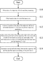
- FIG. 1 is a flow chart of a machine processing trajectory space detecting method according to a first embodiment of the present disclosure.
- FIG. 2 is a flow chart of a machine processing trajectory space detecting method according to a second embodiment of the present disclosure.
- FIG. 3 is a flow chart of a method for determining a positional relationship between a trajectory and a specified space area according to an embodiment of the present disclosure.
- FIG. 4 is a schematic diagram of determining the position of any point on the trajectory in the case that the trajectory is a straight line.
- FIG. 5 is a schematic diagram of determining a point set of the trajectory on an inner side of a curved surface in the case that the trajectory is a straight line.
- FIG. 6 is a schematic diagram of determining the position of any point on the trajectory in the case that the trajectory is an arc.
- FIG. 7 is a schematic diagram of the relationship between the range of ⁇ and the trajectory parameter u.
- FIG. 8 is a schematic diagram of determining a point set of the trajectory on an inner side of a curved surface in the case that the trajectory is an arc.
- FIG. 9 is a schematic diagram of determining the position of any point on the trajectory in the case that the trajectory is a parabola.
- FIG. 10 is a schematic diagram of the structure of a machine processing trajectory space detecting device according to an embodiment of the present disclosure.
- FIG. 11 is a schematic diagram of the structure of a numerical control machine according to an embodiment of the present disclosure.
- FIG. 12 is a schematic diagram of the structure of a numerical control system according to an embodiment of the present disclosure.
- FIG. 13 is a schematic diagram of the structure of a machine processing trajectory space detecting device according to another embodiment of the present disclosure.
- FIG. 1 a flow chart of a machine processing trajectory space detecting method according to a first embodiment of the present disclosure is depicted.
- the method may include the following blocks.
- FIG. 2 a flow chart of a machine processing trajectory space detecting method according to a second embodiment of the present disclosure is depicted.
- the method may include the following blocks.
- trajectory AB may be a straight line, an arc, a parabola, etc.
- any spatial area can enclose a plurality of curved surfaces to form, for example, a cuboid which is formed by enclosing six planes, in which normal vectors of the six planes point to the direction of the center of the cuboid; a cylinder is which formed by enclosing a cylindrical curved surface and two bottom surfaces, in which normal vectors of the two bottom surfaces points to the direction of the center of the cylinder, and a plane normal vector of the cylindrical curved surface points inwardly toward the cylinder.
- the step S 23 can specifically include: utilizing a first inequality as follows to calculate the point set U i of the trajectory AB on the inner side of each curved surface S i :
- M is a projection point of the point P on the curved surface S i , is a normal vector of the curved surface S i pointing to the inner side of the specified space area, and passes through the point M.
- FIG. 3 a flow chart of a method for determining a positional relationship between a trajectory and a specified space area according to an embodiment of the present disclosure is depicted.
- the method may include the following blocks.
- any point on the trajectory AB is assumed as P.
- the point A is a start point of the trajectory AB
- the point B is an end point of the trajectory AB.
- the trajectory parameter u is directly proportional to the distance between the point P and the start point A, and the value of the trajectory parameter u is 0 when the point P coincides with the point A.
- the trajectory parameter u is zero
- the position of the point P is the position of the start point A.
- the trajectory parameter u is positive
- the position of a point which the start point A points to the direction of the unit direction vector is the position of the point P; when the track parameter u is negative, the position of a point which the start point A points to a direction contrary to the unit direction vector is the position of the point P.
- M is a projection point of the point P on the curved surface S i , is a normal vector of the curved surface S i pointing to the inner side of the specified space area, and passes through the point M.
- the range of the trajectory parameter u that is, the point set U i of the straight line AB on the inner side of the surface S i , is obtained by solving the inequality (3).
- the trajectory AB corresponding to the obtained data is an arc
- an arc from the start point A to the end point B which is in a counterclockwise direction is assumed as the arc AB
- O is the center of a circle where the arc AB is
- R is the radius of the circle O.
- the position of P is obtained by rotating a vector counterclockwise for an angle ⁇ with O as the center and R as the radius.
- the position of the point P can be expressed as:
- a cosine value cos ⁇ of the angle ⁇ is calculated based on the coordinate of the point P and the formula (4), and the trajectory parameter u can be expressed using the cosine value cos ⁇ based on the range of 0:
- the position of the point P is determined based on the formula (4) and (5):
- the point M is a projection point of the point P on the curved surface S i
- the point set of the arc AB on the side of the normal vector is determined to satisfy the following inequality based on the first inequality and the formula (8) and (9):
- the range of the trajectory parameter u that is, the point set U i of the arc AB on the inner side of the surface S i , is obtained by solving the inequality (10) and (11).
- FIG. 9 a schematic diagram of determining the position of any point on the trajectory in the case that the trajectory is a parabola is depicted.
- the trajectory AB corresponding to the obtained data is a parabola
- an unit vector which is in the axis direction of the parabola AB is assumed as and an unit direction vector which is in a same plane and perpendicular to the axis direction is assumed as and a
- b and c are the constants of the parabola AB
- the position of the point P can be expressed as:
- the point M is a projection point of the point P on the curved surface S i , is the normal vector of the surface S i pointing to the inner side of the specified space area, and 0 passes through the point M.
- a point set of the parabola AB on a side of the normal vector that is, the point set U i of the parabola AB on the inner side of the surface S i is determined based on the first inequality and the formula (12).
- the device 30 includes:
- a first obtaining unit 31 configured to obtain the data of the trajectory AB of the machine processing.
- a second obtaining unit 32 configured to obtain the spatial data of the specified space area.
- a position determining unit 35 configured to determine the positional relationship between the trajectory AB and the specified space area based on the point sets U i obtained by the calculating unit 34 .
- the calculating unit 34 is configured to calculate the point set U i of the trajectory AB on the inner side of each curved surface S i based on the first inequality as follows:
- M is a projection point of the point P on the curved surface S i , is a normal vector of the curved surface S i pointing to the inner side of the specified space area, and passes through the point M.
- the position determining unit 35 determines that the trajectory AB is on the inner side of the specified space area.
- the position determining unit 35 determines that the trajectory AB is completely outside the specified space area.
- U T is a set of the point sets of the trajectory AB.
- the numerical control machine 40 includes a machine body 41 and a numerical control system 42 installed on the machine body 41 .
- the numerical control system 42 includes a machine processing trajectory space detecting module 43 .
- the machine processing trajectory space detecting module 43 includes:
- a first obtaining unit 430 configured to obtain the data of the trajectory AB of the machine processing.
- a second obtaining unit 431 configured to obtain the spatial data of the specified space area.
- a position determining unit 434 configured to determine the positional relationship between the trajectory AB and the specified space area based on the point sets U i obtained by the calculating unit 433 .
- the numerical control system 42 further includes: an alarm module 44 configured to issue an alarm information when the positional relationship between the trajectory AB and the specified space area determined by the machine processing trajectory space detecting module 43 does not meet a predetermined safety relationship.
- the device 50 in this embodiment is a terminal, which may be a computer.
- the device 50 includes a receiver 51 , a processor 52 , a transmitter 53 , a read only memory 54 , a random access memory 55 , and a bus 56 .
- the receiver 51 is configured to receive data.
- the processor 52 is configured to control the operation of the device 50 , which may be a CPU (Central Processing Unit).
- the processor 52 may be an integrated circuit chip with signal processing capability.
- the processor 52 may also be a general purpose processor, a digital signal processor (DSP), an application specific integrated circuit (ASIC), a field programmable gate array (FPGA), other programmable logic devices, a discrete gate, a transistor logic device, or a discrete hardware component.
- the general purpose processor may be a microprocessor or any conventional processor.
- the transmitter 53 is configured to transmit data.
- the memory may include the read-only memory 54 and the random access memory 55 , and provide instructions and data to the processor 52 .
- a portion of the memory may also include a nonvolatile random access memory (NVRAM).
- NVRAM nonvolatile random access memory
- bus 56 may include a power bus, a control bus, and a status signal bus.
- various buses are designated as the bus 56 in the figure.
- the memory stores the following elements, executable modules or data structures, or their subsets or expansion sets:
- operation instructions include a variety of operation instructions utilized to achieve a variety of operations.
- operation system includes various system programs utilized to implement various basic services and handle hardware-based tasks.
- the processor 52 performs the following operations by calling operation instructions stored in the memory (the operation instructions can be stored in the operation system):
- the processor 52 can be configured to utilize the first inequality as follows to calculate the point set U i of the trajectory AB on the inner side of each curved surface S i :
- M is a projection point of the point P on the curved surface S i
- M is a normal vector of the curved surface S i pointing to the inner side of the specified space area, and passes through the point M.
- the trajectory AB is determined to be on the inner side of all the curved surfaces S i , thereby determining that the trajectory AB is on the inner side of the specified space area, wherein U T is a set of the point sets of the trajectory AB.
- the trajectory AB is determined to be completely outside the specified space area.
- U T is a set of the point sets of the trajectory AB.
- the present disclosure also provides a computer storage medium.
- the computer storage medium includes computer program codes.
- the computer program codes cause a computer processor to execute a machine processing trajectory space detecting method when the computer program codes are executed by the computer processor.
- the method includes:
- the disclosure provides a method, devices, a numerical control machine, and a computer storage medium for detecting machine processing trajectory space, which express the spatial curve via a univariate function so as to participate in the operation of the space area for the curve, express the point sets of any portion of the trajectory via the trajectory parameter set, determines the position of the individual curved surfaces forming the space area and the trajectory, and eventually determine the positions of the space area and the curve. Consequently, the defect of algorithm explosion caused by the space geometry operation which needs to analysis the specific area and straight line type is overcame, which reduces the quantity of operations, and has high reusability.
Landscapes
- Engineering & Computer Science (AREA)
- Human Computer Interaction (AREA)
- Manufacturing & Machinery (AREA)
- Physics & Mathematics (AREA)
- General Physics & Mathematics (AREA)
- Automation & Control Theory (AREA)
- Numerical Control (AREA)
- Processing Or Creating Images (AREA)
Abstract
Description
where, P is any point on the trajectory AB, M is a projection point of the point P on the curved surface Si,
where, P is any point on the trajectory AB, M is a projection point of the point P on the curved surface Si,
where, P is any point on the trajectory AB, M is a projection point of the point P on the curved surface Si,
where, P is any point on the trajectory AB, M is a projection point of the point P on the curved surface Si,
Claims (4)
Applications Claiming Priority (4)
| Application Number | Priority Date | Filing Date | Title |
|---|---|---|---|
| CN201410594724 | 2014-10-29 | ||
| CN201410594724.3A CN104391481B (en) | 2014-10-29 | 2014-10-29 | Machining movement locus space detection method, device and Digit Control Machine Tool |
| CN201410594724.3 | 2014-10-29 | ||
| PCT/CN2015/092551 WO2016066052A1 (en) | 2014-10-29 | 2015-10-22 | Method and device for spatially detecting machining movement trail of machine, and numerical control machine tool |
Publications (2)
| Publication Number | Publication Date |
|---|---|
| US20170343981A1 US20170343981A1 (en) | 2017-11-30 |
| US10691100B2 true US10691100B2 (en) | 2020-06-23 |
Family
ID=52609399
Family Applications (1)
| Application Number | Title | Priority Date | Filing Date |
|---|---|---|---|
| US15/523,368 Active 2036-11-25 US10691100B2 (en) | 2014-10-29 | 2015-10-22 | Method, device for machine processing trajectory space detection and numerical control machine |
Country Status (3)
| Country | Link |
|---|---|
| US (1) | US10691100B2 (en) |
| CN (1) | CN104391481B (en) |
| WO (1) | WO2016066052A1 (en) |
Families Citing this family (4)
| Publication number | Priority date | Publication date | Assignee | Title |
|---|---|---|---|---|
| CN104391481B (en) * | 2014-10-29 | 2018-01-23 | 北京配天技术有限公司 | Machining movement locus space detection method, device and Digit Control Machine Tool |
| CN109213079B (en) * | 2017-06-29 | 2020-10-23 | 深圳模德宝科技有限公司 | Control method and device for automatic production |
| CN108021098B (en) * | 2017-12-05 | 2019-07-19 | 华中科技大学 | A kind of tool path optimization method automatically generating tire-mold safety cylinder body |
| CN110569027B (en) * | 2019-09-10 | 2021-09-14 | 联想(北京)有限公司 | Flow chart layout method and device applied to electronic equipment and electronic equipment |
Citations (8)
| Publication number | Priority date | Publication date | Assignee | Title |
|---|---|---|---|---|
| JP2001242921A (en) | 2000-03-01 | 2001-09-07 | Canon Inc | Processing device control device, processing device control method, processing system, and storage medium |
| US20100063612A1 (en) * | 2008-09-05 | 2010-03-11 | Chung Yuan Christian University | System and method for the on-machine 2-d contour measurement |
| CN102063546A (en) | 2011-01-04 | 2011-05-18 | 山东理工大学 | Rapid generating method of numerical control machining tool path of product triangular Bezier curved surface model |
| CN103279608A (en) | 2013-05-28 | 2013-09-04 | 南京航空航天大学 | Fast searching positioning method for machining operations of large-scaled complex parts |
| CN104391481A (en) * | 2014-10-29 | 2015-03-04 | 北京配天技术有限公司 | Machine processing movement track space detection method and device thereof and numerically-controlled machine tool |
| US20150205283A1 (en) * | 2014-01-21 | 2015-07-23 | Mitsubishi Electric Research Laboratories, Inc. | Method for Generating Trajectory for Numerical Control Process |
| US20160187866A1 (en) * | 2014-10-23 | 2016-06-30 | Fanuc Corporation | Numerical control apparatus |
| US20180207799A1 (en) * | 2015-07-09 | 2018-07-26 | Siemens Aktiengesellschaft | Trajectory determination method for non-productive movements |
Family Cites Families (3)
| Publication number | Priority date | Publication date | Assignee | Title |
|---|---|---|---|---|
| DE102004062163A1 (en) * | 2004-12-20 | 2006-06-22 | Dr. Johannes Heidenhain Gmbh | Method for determining a possible collision of at least two mutually movable objects |
| ATE504869T1 (en) * | 2006-09-30 | 2011-04-15 | Abb Technology Ag | METHOD AND SYSTEM FOR DESIGNING AND CHECKING SAFETY AREAS OF A ROBOT |
| JP5073065B2 (en) * | 2009-01-15 | 2012-11-14 | 三菱電機株式会社 | Collision determination device and collision determination program |
-
2014
- 2014-10-29 CN CN201410594724.3A patent/CN104391481B/en active Active
-
2015
- 2015-10-22 US US15/523,368 patent/US10691100B2/en active Active
- 2015-10-22 WO PCT/CN2015/092551 patent/WO2016066052A1/en not_active Ceased
Patent Citations (8)
| Publication number | Priority date | Publication date | Assignee | Title |
|---|---|---|---|---|
| JP2001242921A (en) | 2000-03-01 | 2001-09-07 | Canon Inc | Processing device control device, processing device control method, processing system, and storage medium |
| US20100063612A1 (en) * | 2008-09-05 | 2010-03-11 | Chung Yuan Christian University | System and method for the on-machine 2-d contour measurement |
| CN102063546A (en) | 2011-01-04 | 2011-05-18 | 山东理工大学 | Rapid generating method of numerical control machining tool path of product triangular Bezier curved surface model |
| CN103279608A (en) | 2013-05-28 | 2013-09-04 | 南京航空航天大学 | Fast searching positioning method for machining operations of large-scaled complex parts |
| US20150205283A1 (en) * | 2014-01-21 | 2015-07-23 | Mitsubishi Electric Research Laboratories, Inc. | Method for Generating Trajectory for Numerical Control Process |
| US20160187866A1 (en) * | 2014-10-23 | 2016-06-30 | Fanuc Corporation | Numerical control apparatus |
| CN104391481A (en) * | 2014-10-29 | 2015-03-04 | 北京配天技术有限公司 | Machine processing movement track space detection method and device thereof and numerically-controlled machine tool |
| US20180207799A1 (en) * | 2015-07-09 | 2018-07-26 | Siemens Aktiengesellschaft | Trajectory determination method for non-productive movements |
Also Published As
| Publication number | Publication date |
|---|---|
| US20170343981A1 (en) | 2017-11-30 |
| CN104391481A (en) | 2015-03-04 |
| CN104391481B (en) | 2018-01-23 |
| WO2016066052A1 (en) | 2016-05-06 |
Similar Documents
| Publication | Publication Date | Title |
|---|---|---|
| US10691100B2 (en) | Method, device for machine processing trajectory space detection and numerical control machine | |
| US11470821B2 (en) | Method for monitoring pet by robot based on grid map and chip | |
| US10429408B2 (en) | Vehicle monitoring module | |
| US11385059B2 (en) | Method for determining heading of unmanned aerial vehicle and unmanned aerial vehicle | |
| EP3423849B1 (en) | Ultra-fast autonomous clock monitoring circuit for safe and secure automotive applications | |
| WO2021082225A1 (en) | Vehicle attitude detection method and device, vehicle-mounted terminal, vehicle and medium | |
| CN115053145A (en) | Method and system for locating a transponder of a wireless communication object and personal protection system | |
| CN115556827A (en) | Course angle determination method and device of automatic driving vehicle and electronic equipment | |
| CN112689842B (en) | A target detection method and device | |
| CN107450069A (en) | Moving Object Detection device, program and recording medium | |
| CN109238282B (en) | Robot positioning detection method and device and computer readable medium | |
| CN114631035A (en) | Method for acquiring point cloud clustering wave gate, radar, movable platform and storage medium | |
| CN104346306A (en) | System and method of high integrity DMA operation | |
| CN114926413A (en) | Method and device for detecting wafer surface defects, computer equipment and storage medium | |
| CN113050612B (en) | Medium printed with positioning mark, image processing method and automatic guided vehicle | |
| CN119993892A (en) | A pre-alignment eccentricity calibration method, device, equipment and medium based on wafer pre-alignment device | |
| CN114913208A (en) | Method and device for determining tail end extension track and electronic equipment | |
| EP3781964B1 (en) | Determining a location of a mobile device | |
| CN110202571B (en) | Method, device and equipment for setting sensor address and storage medium | |
| CN112415500B (en) | Target object position detection method and related device | |
| US20250028036A1 (en) | Positioning method and multi-radar positioning system | |
| US20260080690A1 (en) | Free space detection and park-able free space detection for occupancy grids using sensor measurements | |
| CN111563358B (en) | Method, apparatus and storage medium for inserting pairing graph | |
| CN116225035A (en) | Gesture monitoring method and device, storage medium and unmanned equipment | |
| López | Parabolic surfaces in hyperbolic space with constant Gaussian curvature |
Legal Events
| Date | Code | Title | Description |
|---|---|---|---|
| AS | Assignment |
Owner name: SHENZHEN A&E INTELLIGENT TECHNOLOGY INSTITUTE CO., LTD., CHINA Free format text: ASSIGNMENT OF ASSIGNORS INTEREST;ASSIGNOR:CHEN, XIAOYING;REEL/FRAME:042187/0958 Effective date: 20170420 Owner name: SHENZHEN A&E INTELLIGENT TECHNOLOGY INSTITUTE CO., Free format text: ASSIGNMENT OF ASSIGNORS INTEREST;ASSIGNOR:CHEN, XIAOYING;REEL/FRAME:042187/0958 Effective date: 20170420 |
|
| STPP | Information on status: patent application and granting procedure in general |
Free format text: DOCKETED NEW CASE - READY FOR EXAMINATION |
|
| STPP | Information on status: patent application and granting procedure in general |
Free format text: NON FINAL ACTION MAILED |
|
| STPP | Information on status: patent application and granting procedure in general |
Free format text: RESPONSE TO NON-FINAL OFFICE ACTION ENTERED AND FORWARDED TO EXAMINER |
|
| STPP | Information on status: patent application and granting procedure in general |
Free format text: NOTICE OF ALLOWANCE MAILED -- APPLICATION RECEIVED IN OFFICE OF PUBLICATIONS |
|
| STPP | Information on status: patent application and granting procedure in general |
Free format text: PUBLICATIONS -- ISSUE FEE PAYMENT VERIFIED |
|
| STCF | Information on status: patent grant |
Free format text: PATENTED CASE |
|
| MAFP | Maintenance fee payment |
Free format text: PAYMENT OF MAINTENANCE FEE, 4TH YR, SMALL ENTITY (ORIGINAL EVENT CODE: M2551); ENTITY STATUS OF PATENT OWNER: SMALL ENTITY Year of fee payment: 4 |