US10690533B2 - Illumination pattern system and methods for 3D-time of flight systems - Google Patents
Illumination pattern system and methods for 3D-time of flight systems Download PDFInfo
- Publication number
- US10690533B2 US10690533B2 US15/858,411 US201715858411A US10690533B2 US 10690533 B2 US10690533 B2 US 10690533B2 US 201715858411 A US201715858411 A US 201715858411A US 10690533 B2 US10690533 B2 US 10690533B2
- Authority
- US
- United States
- Prior art keywords
- axis
- illumination
- output beam
- volume
- distal end
- Prior art date
- Legal status (The legal status is an assumption and is not a legal conclusion. Google has not performed a legal analysis and makes no representation as to the accuracy of the status listed.)
- Active
Links
Images


Classifications
-
- G—PHYSICS
- G01—MEASURING; TESTING
- G01F—MEASURING VOLUME, VOLUME FLOW, MASS FLOW OR LIQUID LEVEL; METERING BY VOLUME
- G01F17/00—Methods or apparatus for determining the capacity of containers or cavities, or the volume of solid bodies
-
- G—PHYSICS
- G01—MEASURING; TESTING
- G01B—MEASURING LENGTH, THICKNESS OR SIMILAR LINEAR DIMENSIONS; MEASURING ANGLES; MEASURING AREAS; MEASURING IRREGULARITIES OF SURFACES OR CONTOURS
- G01B11/00—Measuring arrangements characterised by the use of optical techniques
- G01B11/24—Measuring arrangements characterised by the use of optical techniques for measuring contours or curvatures
- G01B11/25—Measuring arrangements characterised by the use of optical techniques for measuring contours or curvatures by projecting a pattern, e.g. one or more lines, moiré fringes on the object
- G01B11/2513—Measuring arrangements characterised by the use of optical techniques for measuring contours or curvatures by projecting a pattern, e.g. one or more lines, moiré fringes on the object with several lines being projected in more than one direction, e.g. grids, patterns
-
- G—PHYSICS
- G01—MEASURING; TESTING
- G01B—MEASURING LENGTH, THICKNESS OR SIMILAR LINEAR DIMENSIONS; MEASURING ANGLES; MEASURING AREAS; MEASURING IRREGULARITIES OF SURFACES OR CONTOURS
- G01B11/00—Measuring arrangements characterised by the use of optical techniques
-
- G—PHYSICS
- G01—MEASURING; TESTING
- G01S—RADIO DIRECTION-FINDING; RADIO NAVIGATION; DETERMINING DISTANCE OR VELOCITY BY USE OF RADIO WAVES; LOCATING OR PRESENCE-DETECTING BY USE OF THE REFLECTION OR RERADIATION OF RADIO WAVES; ANALOGOUS ARRANGEMENTS USING OTHER WAVES
- G01S17/00—Systems using the reflection or reradiation of electromagnetic waves other than radio waves, e.g. lidar systems
- G01S17/88—Lidar systems specially adapted for specific applications
- G01S17/89—Lidar systems specially adapted for specific applications for mapping or imaging
- G01S17/894—Three-dimensional [3D] imaging with simultaneous measurement of time-of-flight at a two-dimensional [2D] array of receiver pixels, e.g. time-of-flight cameras or flash lidar
-
- G—PHYSICS
- G01—MEASURING; TESTING
- G01S—RADIO DIRECTION-FINDING; RADIO NAVIGATION; DETERMINING DISTANCE OR VELOCITY BY USE OF RADIO WAVES; LOCATING OR PRESENCE-DETECTING BY USE OF THE REFLECTION OR RERADIATION OF RADIO WAVES; ANALOGOUS ARRANGEMENTS USING OTHER WAVES
- G01S7/00—Details of systems according to groups G01S13/00, G01S15/00, G01S17/00
- G01S7/48—Details of systems according to groups G01S13/00, G01S15/00, G01S17/00 of systems according to group G01S17/00
- G01S7/481—Constructional features, e.g. arrangements of optical elements
- G01S7/4814—Constructional features, e.g. arrangements of optical elements of transmitters alone
- G01S7/4815—Constructional features, e.g. arrangements of optical elements of transmitters alone using multiple transmitters
-
- G—PHYSICS
- G02—OPTICS
- G02B—OPTICAL ELEMENTS, SYSTEMS OR APPARATUS
- G02B5/00—Optical elements other than lenses
- G02B5/02—Diffusing elements; Afocal elements
- G02B5/0205—Diffusing elements; Afocal elements characterised by the diffusing properties
Definitions
- Three-dimensional (3D) sensors are used to measure loads within vehicle trailers and shipping containers.
- 3D sensors for example, measure distances from a back-wall of a trailer/container to the nearest load-wall inside that trailer/container. From these distances, operators can determine such metrics as the available storage space within a volume
- SL sensors structured light (SL) 3D sensors used in Trailer Monitor Units (TMUs) mounted on vehicle trailers.
- TMUs Trailer Monitor Units
- SL sensors a projector projects an image into a volume (of the trailer/container), multiple cameras capture renditions of the projected image, and these renditions are image processed to determine relative distances of the back wall and objects in the volume.
- the process requires complex and time-consuming image processing, and the results are often inaccurate.
- SL sensors are highly dependent on the light intensity in a volume. Yet, light intensity changes dramatically with the number of objects in the volume, or when differently shaped or differently sized objects are placed in the volume. The result is that conventional 3D sensors are of limited effectiveness in “smart” shipping application, where accurate assessment of trailer loads is desired.
- FIG. 1 is a schematic illustration of a prior art illumination system.
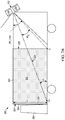
- FIGS. 2A and 2B are example schematic illustrations of a top view and a side view, respectively, of a vehicle trailer with an example illumination system producing an example illumination pattern, in accordance with some embodiments.
- FIG. 3 is a schematic of an example illumination system, in accordance with some embodiments.
- FIG. 4 is an illustration of an example illumination pattern criterion, in accordance with some embodiments.
- FIGS. 5A and 5B are further examples illumination pattern criteria, with varying shape factors, in accordance with some embodiments.
- FIG. 6 illustrates another example vehicle trailer having an illumination system like that of FIG. 3 used for time-of-flight sensing applications, in accordance with some embodiments.
- the embodiments of the present disclosure are directed to techniques for illuminating a volume with an illumination pattern that maintains illumination irradiances for sufficient on and off axis illumination of objects within a volume, such as a vehicle trailer or shipping container.
- an illumination system includes a light source positioned at a proximal end of a volume, where the illumination system is configured to emit an output beam into the volume.
- the volume may be a shipping trailer, such as vehicle trailer, or a shipping container, or some other volume within which multiple objects for shipping may be placed.
- the illumination system may further include a diffuser positioned to receive the output beam from the illumination system. The diffuser may diffuse that output beam so that the output beam extends from a distal end plane of the volume to an interstitial plane in the volume, such as a plane of the nearest object placed within the volume.
- the diffuser may be configured such that the output beam has a threshold illumination intensity such that the irradiance produced at a lateral off-axis extent of the distal end plane is above a threshold irradiance amount, and the diffuser may be further configured such that the illumination intensity of the output beam produces an irradiance at a lateral off-axis extent of the interstitial plane at or above this threshold irradiance amount at the lateral off-axis extent of the distal end plane.
- the result is the illumination of a volume, also termed herein an illumination volume, that satisfies a minimum irradiance threshold condition throughout the depth and lateral extent of that illumination volume.
- a system for monitoring a volume. That system may include a processor, a memory, and an optical sensor, as well as an illumination system as described, all at a proximal end of the volume.
- the light source is an infrared light source and the optical sensor is an infrared sensor.
- the processor controls the optical sensor to measure infrared radiation reflected from an object within the volume.
- the processor can determine distances of objects within the volume from the measured infrared radiation.
- the processor can control the illumination intensity of the light source based on the measured infrared radiation.
- the system is a time-of-flight system that measures distances of objects in the volume, by using a time-of-flight measurement.
- FIG. 1 is a diagram of a conventional illumination system 100 , as used for 3D sensors such as those used in video game environments.
- a light source 101 which is commonly a laser light source, produces an output beam 102 , while a diffuser 104 receives that output beam and converts it to an affected output beam 102 ′ that evenly displaces the beam over solid angle volume 106 , thereby forming a uniform irradiance of a flat screen 108 .
- Such a conventional configuration is useful for gaming applications, which are short-range applications.
- the uniform irradiance at the screen 108 is important to optimize detection of an object in the solid angle volume 106 . For example, as a gaming controller is moved anywhere within the volume, the 3D sensor can detect the gaming controller with the same accuracy. This uniformity is achievable, in part, because over the short distances of gaming applications, e.g., 5 m or shorter, the 3D sensor can operate effectively without use of a high intensity light out.
- FIGS. 2A and 2B illustrate a schematic of an illumination system environment 200 in accordance with various example embodiments herein.
- FIG. 2A illustrates a top view of the illumination system environment 200
- FIG. 2B illustrates a side view.
- the environment 200 may be implemented in trailer-based vehicle shipping application, as shown.
- the environment 200 includes a vehicle trailer 202 having a distal end 204 , nearest to a vehicle cab 206 , and a proximal end 208 , at which personnel typically will access the trailer 202 by loading/offload objects for/from shipping.
- proximal end 208 For loading the vehicle trailer 202 , typically personnel will access the proximal end 208 carrying objects onto a bed of the vehicle trailer 202 , for example, using a forklift or other container carrier.
- autonomous vehicles may be used to carry objects into the vehicle trailer 202 .
- Initial objects are typically loaded against a back wall (at a distal end plane) 210 of the vehicle trailer 202 , and subsequent objects are loaded until some or all of the back wall 210 is covered with objects.
- Objects will continue to be placed within the vehicle trailer 202 until a shipping volume within the vehicle trailer 202 is completed.
- the environment 200 further includes an illumination system 212 positioned at the proximal end 208 .
- the illumination system 212 comprises a light source 214 that generates an output beam that is to be provided into the volume of the vehicle trailer 202 .
- the light source 214 may contain one or more laser light sources, one or more light emitting diodes (LEDs), a combination thereof, or other suitable light source.
- a diffuser 216 is also included within the illumination system 212 and is positioned to receive an output beam from the light source 214 and diffuse that output beam, in accordance with examples herein.
- the illumination system 212 with the combined light source 214 and diffuser 216 , is configured to illuminate an illumination volume 218 within the vehicle trailer 202 , where that illumination volume 218 extends from the back wall 210 to an interstitial plane 220 located between the distal end 204 and the proximal end 208 .
- the interstitial plane 220 is marked with the points “A” and “C” in FIGS. 2A and 2B , respectively, where point “A” indicates a lateral off-axis extent of the interstitial plane 220 , from an illumination x-axis 222 , indicated by an off-axis angle, ⁇ x.
- the point “C” indicates another lateral off-axis extent of the interstitial plane 220 , from an illumination y-axis 224 , indicated by off-axis angle, ⁇ y.
- a lateral off-axis extent is indicated by the point “A O ” measured from the illumination x-axis 222
- the illumination system 212 is configured to provide an output beam with an illumination intensive pattern that illuminates the volume 218 , where that illumination pattern meets particular pattern criteria, and where the criteria are based on obtaining a desired irradiance over an illumination volume that extends from the back wall 20 to the interstitial plane 220 .
- a first illumination intensity criterion is that the illumination system 212 be configured to maximize irradiance of the vehicle trailer 202 , in particular at the back wall 210 (maximum back wall irradiance), while maintaining that irradiance (and thus the illumination intensity from the light source) at or below prescribed safety levels for personnel.
- Various examples of safety levels may be used to define the maximum back wall irradiance.
- An example safety level for a laser light source is to have a maximum illumination intensity from the laser source as set forth in the requirements of Class 1 for lasers, defined by 21 Code of Federal Regulations 1040 (21 C.F.R. 1040) in the United States, or as set forth internationally by the International Electrotechnical Commission (EIC) under regular EIC 60825. Either of these may be considered as defining a maximum permissible accessible emission limit.
- a second illumination intensity criterion is to maintain an off-axis extent irradiance of the interstitial plane 220 (i.e., at points “A” and/or “C”) at or above a minimum irradiance established at the back wall. While other design criteria may be established, these two criteria, it has been found, allow for suitably strong irradiances at the back wall 210 , while maintaining a minimum useful irradiance over the entire illumination volume 218 , including over the entire depth and lateral extent, such that the entire illumination volume 218 is sufficiently illuminated for time of flight 3D sensor measurements.
- FIG. 3 illustrates an example implementation of an illumination system, such as the illumination system 212 , formed as trailer monitoring unit configured to satisfy the aforementioned illumination pattern criteria.
- Illumination system 300 includes a processor 302 and memory 304 configured to perform any of the functions described herein.
- the illumination system 300 includes a light source 306 and a diffuser 308 positioned to receive an output beam from the light source 306 and alter that beam to produce the desired illumination pattern projected into the vehicle trailer 202 .
- the processor 302 is communicatively coupled to the light source 306 to control operation thereof.
- the diffuser 308 may be a static element configured to produce a single desired illumination pattern.
- the diffuser 308 may be a thin film structure or a bulk structure, a flexible structure or rigid structure, by way of example. In other embodiments, the diffuser 308 may be a dynamic element that can be changed to produce different illumination patterns under different conditions. In some such embodiments, the diffuser 308 may be an electronically-controlled element, e.g., an electronically-controlled light shaping diffuser available from Luminit of Torrance, Calif., that is communicatively coupled to the processor 302 for controlling which illumination pattern is generated by the diffuser 308 .
- the illumination system 300 further includes an optical sensor 310 communicatively coupled to the processor 302 for performing time-of-flight measurements and other functions, as described herein.
- the diffuser 308 is configured to produce an illumination intensity as follows.
- the illumination intensity of the output beam from the illumination system 300 is indicated by I( ⁇ ), where ⁇ is measured from a central (illumination) axis where the illumination intensity is highest and where output beam produces the highest irradiance at any plane within the volume (i.e., where the illumination axis interest that plane).
- I( ⁇ ) the illumination intensity of the output beam from the illumination system 300
- ⁇ is measured from a central (illumination) axis where the illumination intensity is highest and where output beam produces the highest irradiance at any plane within the volume (i.e., where the illumination axis interest that plane).
- the diffuser 308 may be configured to satisfy standard EIC EN60825-1:2014, in which the accessible emission limit (AEL) is expressed in terms of radiation power within a 7 mm diameter detector (maximum size of eye pupil) at 100 mm from the diffuser surface (closest eye accommodation distance).
- AEL limits radiation intensity (power per solid angle) of illumination source Imax:
- I max AEL ⁇ ⁇ ⁇ 3.5 ⁇ ⁇ mm 2 100 ⁇ ⁇ mm 2 ( 1 )
- the AEL is linearly proportional to angular size of the laser spot on diffuser as seen from 100 mm distance.
- ⁇ When the viewing angle to diffuser (between eye sight and diffuser normal) ⁇ increases, angular spot size decreases. Therefore, AEL is a function of the viewing angle ⁇ to the diffuser.
- a conservative estimation of EIC EN60825-1:2014 was applied, such that AEL was treated as proportional to cosine angle ⁇ , resulting in an expression of the maximum illumination intensity, per angle, of the diffused output beam: I max ( ⁇ ) ⁇ cos( ⁇ ) (2)
- This relationship contrasts with conventional distribution, like of FIG. 1 , in which the radiation intensity increased with angle ⁇ to ensure uniform irradiance at the distal plane.
- the expression (3) provides the illumination intensity that is to be maintained over a range of off-axis angles whether in the x-direction (horizontal illumination intensity) or in the y-direction (vertical illumination intensity).
- I x ( ⁇ ) the suitable angles, as defined in FIGS.
- ⁇ x0 ⁇ x ⁇ x0 and ⁇ y ⁇ 0 are such that ⁇ x0 ⁇ x ⁇ x0 and ⁇ y ⁇ 0.
- the suitable angles are such that ⁇ y0 ⁇ y ⁇ y0 .
- these illumination intensity expressions are satisfied for any angle, ⁇ , for light illuminating an illumination volume, that is, ⁇ xA ⁇ x ⁇ xA and ⁇ y ⁇ 0 for the interstitial plane along the x-axis and ⁇ yC ⁇ y ⁇ yC for the interstitial plane along the y-axis.
- ⁇ xA and ⁇ yA will depend on the diffuser and are shown by ⁇ x_max and ⁇ y_max , in the illustrated example. These maximum angles also determine the nearest position of the interstitial plane to the proximal end, and thus the maximum angles define the maximum size of the illumination volume measured from the back wall.
- the diffuser 308 is further configured to produce an output beam with an illumination intensity criteria, I min ( ⁇ ), that minimizes off-axis irradiance over the illumination volume.
- I min an illumination intensity criteria
- the irradiance at the off-axis extent of the interstitial plane 220 i.e., at point “A,” should be equal to or larger than irradiance at the back wall 210 at the corresponding off-axis extent (point “A O ”).
- irradiance, Ea at the point “A” is defined.
- the irradiance, Ea as function of vehicle trailer width, W, angle ⁇ x , and source illumination intensity I( ⁇ x ), is expressed as follows:
- Ea ⁇ ( ⁇ x ) I ⁇ ( ⁇ x ) ⁇ cos ⁇ ( ⁇ x ) [ .5 ⁇ ⁇ W sin ⁇ ( ⁇ x ) ] 2 ( 4 )
- Ea should not decrease with angle ⁇ x. Therefore, Ea can be expressed as:
- I x ⁇ ( ⁇ x ) ⁇ I x_min ⁇ ( ⁇ x ) I x ⁇ ( ⁇ x ⁇ ⁇ 0 ) ⁇ cos ⁇ ⁇ ( ⁇ x ⁇ ⁇ 0 ) ⁇ sin ⁇ ( ⁇ x ⁇ ⁇ 0 ) 2 cos ⁇ ⁇ ( ⁇ x ) ⁇ sin ⁇ ( ⁇ x ) 2 ( 6 )
- irradiance, Ec of a bottom of the interstation plane 220 (at point C) should be equal to or larger than irradiance of at point “C O ,” at the back wall. From that similar condition, we determine a vertical intensity that the illumination patter from the diffuser 308 is to follow, in various embodiments as expression (7):
- I y ⁇ ( ⁇ y ) ⁇ I y_min ⁇ ( ⁇ y ) I y ⁇ ( ⁇ y ⁇ ⁇ 0 ) ⁇ cos ⁇ ⁇ ( ⁇ ) ⁇ sin ⁇ ( ⁇ ) 2 cos ⁇ ⁇ ( ⁇ + ⁇ y ) ⁇ sin ⁇ ( ⁇ + ⁇ y ) 2 ( 7 )
- ⁇ is the tilt of the illumination system mounted at a proximal end of a vehicle trailer, as shown by way of example in FIG. 2B .
- FIG. 4 is an illustration of an intensity acceptability region 400 for a horizontal illumination intensity of an output beam emitted into a vehicle trailer, as determined by the illumination system in accordance with various embodiments.
- the acceptability region 400 is bounded, at the upper end, by a maximum illumination intensity curve 402 and, at the lower end, by a minimum illumination intensity curve 404 .
- the curves 402 and 404 were determined from the example expressions (3) and (6). It will be appreciated, however, that these expressions are merely examples, and that other expressions (or illumination intensity criteria) may be used to determine the maximum curve 402 and minimum curve 404 . While FIG.
- FIG. 4 illustrates an acceptability region for a horizontal illumination intensity
- a similar profile would exist for a vertical illumination intensity, expect that in the illustrated example the diffuser is positioned to produce output beam at an angle relative to longitudinal y-axis.
- an acceptability region of irradiance may be also be defined, and would have a similar profile, albeit as a measure of irradiance as a function of off-axis angle.
- FIGS. 5A and 5B illustrate a plurality of example intensity acceptability regions, each determined by a design criterion factor and each of which may be used for more general scenarios of some embodiments herein.
- FIG. 5A illustrates illumination intensity acceptability regions for a horizontal illumination intensity of an output beam emitted into a vehicle trailer.
- FIG. 5B illustrates illumination intensity acceptability regions for vertical illumination intensity of that output beam.
- the illumination pattern criteria for the acceptability regions in FIGS. 5A and 5B satisfy the following expressions:
- I x ⁇ ( ⁇ x , kx ) min ⁇ [ cos ⁇ ( ⁇ x ) , ( cos ⁇ ⁇ ( ⁇ x ⁇ ⁇ 0 ) ⁇ sin ⁇ ( ⁇ x ⁇ ⁇ 0 ) 2 cos ⁇ ⁇ ( ⁇ x ) ⁇ sin ⁇ ( ⁇ x ) 2 ) kx ] ( 8 )
- I y ⁇ ( ⁇ y , ky : if ⁇ ⁇ ⁇ y ⁇ 0 , cos ⁇ ( ⁇ y ) , min ⁇ [ cos ⁇ ( ⁇ y ) , ( cos ⁇ ⁇ ( ⁇ ) ⁇ sin ⁇ ( ⁇ ) 2 cos ⁇ ⁇ ( ⁇ y + ) ⁇ sin ⁇ ( ⁇ y + ⁇ ) 2 ) ky ] ] ( 9 ) ⁇ I ⁇ ( 0
- the expressions (8) and (9) each depend on an additional design criterion, shape factor, expressed as kx for the horizontal axis shape factor and ky for the vertical axis shape factor.
- the shape factor, k is used to further define the resulting illumination intensity generated by a diffuser.
- the shape factor can range from 0 to 1.
- the result is a minimum illumination intensity, as shown in FIGS. 5A and 5B .
- the largest maximum intensity curve 604 corresponds to a shape factor of 0.
- expression (8) can singularly define the minimum and maximum horizontal illumination intensity conditions, by virtue of having different shape factors.
- the same is true for expression (9) regarding vertical illumination intensity conditions.
- the shape factor, k is a variable that can be used to trade off efficient of illumination of a back wall versus non-uniformity of intensity as an interstitial plane with the vehicle trailer.
- a processor may be programed to adjust the shape factor to a desired value for the particular vehicle trailer to be illuminated.
- Vehicle trailer variables such as length, width, and height may be used by the processor to determine a desired shape factor, which is then used to determine a diffusion profile for the diffusor.
- the processor may then communicate the desired diffusion profile to the diffusor.
- the illumination system 300 may be used for time-of-flight 3D sensor measurements with a vehicle trailer, an example of which is described in relation to FIG. 6 . These time-of-flight measurements may be used to identify objects within the vehicle trailer, to identify an interstitial plane corresponding to the nearest object in the vehicle trailer, to determine a consumed volume within a vehicle trailer, to determine an available volume within the vehicle trailer, to determine dimensions of objects with the trailer, and/or other applications.
- the light source 306 is an infrared laser source and the optical sensor 310 is a time-of-flight 3D image sensor configured to measure infrared light reflected (i.e., radiance) from within a vehicle trailer 600 , e.g., off a back wall and off of objects in the vehicle trailer.
- the processor 302 controls the light source 306 and the diffuser 308 to produce an illumination output beam having a desired illumination intensity pattern.
- the processor 302 controls the optical sensor 310 to then collect infrared image data from within the vehicle trailer and analyze that image data, either within the optical sensor 310 or within the processor 302 , to determine 3D image data, from which the various characteristic values can be determined for the vehicle trailer and objects therein.
- the illumination system 300 can determine a location of a back wall 602 of the vehicle trailer 600 , as well as locations of side walls 604 , top wall 606 , and bottom wall 608 . From there, the illumination system 300 can determine the overall volume of the vehicle trailer 600 .
- the illumination system 300 can also determine a location of a closest object 609 within the vehicle trailer 600 , from which the illumination system 300 can identify the location of an interstitial plane 610 . From there, the illumination system 300 can determine, applying the techniques herein, an illumination volume 612 and the illumination pattern needed to satisfy illumination criteria (and/or irradiance criteria) stored within the memory 304 .
- a light source may include two laser emitters, each having a different diffuser, where one laser emitter-diffuser pair may produce a first shape factor, k 1 , illumination pattern and a different laser emitter-diffuser pair may produce a second shape factor, k 2 , illumination pattern, where k 1 ⁇ k 2 , where k 1 >k 2 or where k 1 ⁇ k 2 , for example.
- a processor within the illumination system would then determine which laser emitter-diffusion pair is used to produce the desired illumination volume.
- the processor may be programed to control each of the pairs to fill different portions of the illumination volume, such that the entire volume is filled from combining the output beam from each.
- one pair is used to illuminate a back wall to satisfy a desired first illumination criterion, while the other pair is used to illuminate an interstitial plane to satisfy a desired second illumination criterion.
- both pairs may be used to illuminate a back wall, and only one of the pairs is used to illuminate an interstitial plane.
- the present techniques provide example systems and methods for an illumination system that produces an illumination intensity pattern that can minimize the number of light sources needed for long distance, e.g., 10 m to 20 m, 3D time-of-flight applications, including the 24 ft to 53 ft vehicle trailer length size common in vehicle shipping applications.
- the techniques herein may be implemented in trailer monitoring units have time-of-flight 3D sensors, although they are not limited to such applications, but rather may be used in any number of applications in which illumination criteria for a illumination volume are to be maintained.
- a includes . . . a”, “contains . . . a” does not, without more constraints, preclude the existence of additional identical elements in the process, method, article, or apparatus that comprises, has, includes, contains the element.
- the terms “a” and “an” are defined as one or more unless explicitly stated otherwise herein.
- the terms “substantially”, “essentially”, “approximately”, “about” or any other version thereof, are defined as being close to as understood by one of ordinary skill in the art, and in one non-limiting embodiment the term is defined to be within 10%, in another embodiment within 5%, in another embodiment within 1% and in another embodiment within 0.5%.
- the term “coupled” as used herein is defined as connected, although not necessarily directly and not necessarily mechanically.
- a device or structure that is “configured” in a certain way is configured in at least that way, but may also be configured in ways that are not listed.
- processors such as microprocessors, digital signal processors, customized processors and field programmable gate arrays (FPGAs) and unique stored program instructions (including both software and firmware) that control the one or more processors to implement, in conjunction with certain non-processor circuits, some, most, or all of the functions of the method and/or apparatus described herein.
- processors or “processing devices” such as microprocessors, digital signal processors, customized processors and field programmable gate arrays (FPGAs) and unique stored program instructions (including both software and firmware) that control the one or more processors to implement, in conjunction with certain non-processor circuits, some, most, or all of the functions of the method and/or apparatus described herein.
- FPGAs field programmable gate arrays
- unique stored program instructions including both software and firmware
- an embodiment can be implemented as a computer-readable storage medium having computer readable code stored thereon for programming a computer (e.g., comprising a processor) to perform a method as described and claimed herein.
- Examples of such computer-readable storage mediums include, but are not limited to, a hard disk, a CD-ROM, an optical storage device, a magnetic storage device, a ROM (Read Only Memory), a PROM (Programmable Read Only Memory), an EPROM (Erasable Programmable Read Only Memory), an EEPROM (Electrically Erasable Programmable Read Only Memory) and a Flash memory.
Landscapes
- Physics & Mathematics (AREA)
- General Physics & Mathematics (AREA)
- Engineering & Computer Science (AREA)
- Optics & Photonics (AREA)
- Computer Vision & Pattern Recognition (AREA)
- Computer Networks & Wireless Communication (AREA)
- Radar, Positioning & Navigation (AREA)
- Remote Sensing (AREA)
- Fluid Mechanics (AREA)
- Electromagnetism (AREA)
- Length Measuring Devices By Optical Means (AREA)
- Circuit Arrangement For Electric Light Sources In General (AREA)
Abstract
Description
The AEL is linearly proportional to angular size of the laser spot on diffuser as seen from 100 mm distance. When the viewing angle to diffuser (between eye sight and diffuser normal) θ increases, angular spot size decreases. Therefore, AEL is a function of the viewing angle θ to the diffuser. A conservative estimation of EIC EN60825-1:2014 was applied, such that AEL was treated as proportional to cosine angle θ, resulting in an expression of the maximum illumination intensity, per angle, of the diffused output beam:
I max(θ)∝ cos(θ) (2)
This relationship contrasts with conventional distribution, like of
I(θ)≤I max(θ)=I O cos(θ) (3)
where IO is the on-axis illumination intensity, i.e., at θ=0. The expression (3) provides the illumination intensity that is to be maintained over a range of off-axis angles whether in the x-direction (horizontal illumination intensity) or in the y-direction (vertical illumination intensity). In the example the x-direction, and considering irradiance at the back wall, i.e., Ix(θ), the suitable angles, as defined in
Ea should not decrease with angle θx. Therefore, Ea can be expressed as:
where L is the length of back wall to the diffuser, e.g., the length of the vehicle trailer.
where α is the tilt of the illumination system mounted at a proximal end of a vehicle trailer, as shown by way of example in
where like definitions to that of
Claims (7)
I(θ)≤I max(θ)=I O cos(θ),
I(θ)≤I max(θ)=I O cos(θ),
Priority Applications (3)
| Application Number | Priority Date | Filing Date | Title |
|---|---|---|---|
| US15/858,411 US10690533B2 (en) | 2017-12-29 | 2017-12-29 | Illumination pattern system and methods for 3D-time of flight systems |
| DE102018131853.7A DE102018131853B4 (en) | 2017-12-29 | 2018-12-12 | Illumination pattern system and associated methods for 3D time-of-flight systems |
| FR1874339A FR3076897B1 (en) | 2017-12-29 | 2018-12-28 | LIGHTING PATTERN GENERATION SYSTEM AND METHODS FOR 3D FLIGHT TIME SYSTEMS |
Applications Claiming Priority (1)
| Application Number | Priority Date | Filing Date | Title |
|---|---|---|---|
| US15/858,411 US10690533B2 (en) | 2017-12-29 | 2017-12-29 | Illumination pattern system and methods for 3D-time of flight systems |
Publications (2)
| Publication Number | Publication Date |
|---|---|
| US20190204134A1 US20190204134A1 (en) | 2019-07-04 |
| US10690533B2 true US10690533B2 (en) | 2020-06-23 |
Family
ID=66816915
Family Applications (1)
| Application Number | Title | Priority Date | Filing Date |
|---|---|---|---|
| US15/858,411 Active US10690533B2 (en) | 2017-12-29 | 2017-12-29 | Illumination pattern system and methods for 3D-time of flight systems |
Country Status (3)
| Country | Link |
|---|---|
| US (1) | US10690533B2 (en) |
| DE (1) | DE102018131853B4 (en) |
| FR (1) | FR3076897B1 (en) |
Families Citing this family (1)
| Publication number | Priority date | Publication date | Assignee | Title |
|---|---|---|---|---|
| WO2024168419A1 (en) * | 2023-02-17 | 2024-08-22 | Binsentry Inc. | Method of mapping bulk material in a bin using machine learning |
Citations (11)
| Publication number | Priority date | Publication date | Assignee | Title |
|---|---|---|---|---|
| US4677473A (en) * | 1985-06-21 | 1987-06-30 | Matsushita Electric Works, Ltd. | Soldering inspection system and method therefor |
| US5473436A (en) * | 1993-01-12 | 1995-12-05 | Kabushiki Kaisha Toshiba | Surface shape measurement device with slit plate and single photoelectric converter |
| US5598280A (en) * | 1993-03-23 | 1997-01-28 | Dai Nippon Printing Co., Ltd. | Film lens and a surface light source using the same |
| US6542236B1 (en) * | 1998-08-27 | 2003-04-01 | Samsung Electronics Co., Ltd. | Illuminating and optical apparatus for inspecting soldering of printed circuit board |
| US20050264796A1 (en) * | 2003-09-10 | 2005-12-01 | Shaw Eugene L | Non-destructive testing and imaging |
| US7545516B2 (en) * | 2005-12-01 | 2009-06-09 | University Of Waterloo | Full-field three-dimensional measurement method |
| US20090147239A1 (en) * | 2005-09-02 | 2009-06-11 | Neptec | Apparatus and method for tracking an object |
| US20100103676A1 (en) * | 2008-10-28 | 2010-04-29 | Noeth Raymond A | Energy efficient illumination apparatus and method for illuminating surfaces |
| US20100177164A1 (en) * | 2005-10-11 | 2010-07-15 | Zeev Zalevsky | Method and System for Object Reconstruction |
| US20110043768A1 (en) * | 2009-04-10 | 2011-02-24 | Kenji Nakayama | Image display apparatus |
| US20150167934A1 (en) * | 2008-10-28 | 2015-06-18 | Raymond A. Noeth | Energy efficient illumination apparatus and method for illuminating surfaces |
Family Cites Families (1)
| Publication number | Priority date | Publication date | Assignee | Title |
|---|---|---|---|---|
| MX389489B (en) | 2015-11-18 | 2025-03-20 | Symbol Technologies Llc | METHODS AND SYSTEMS FOR ESTIMATING CONTAINER FILLING. |
-
2017
- 2017-12-29 US US15/858,411 patent/US10690533B2/en active Active
-
2018
- 2018-12-12 DE DE102018131853.7A patent/DE102018131853B4/en active Active
- 2018-12-28 FR FR1874339A patent/FR3076897B1/en active Active
Patent Citations (11)
| Publication number | Priority date | Publication date | Assignee | Title |
|---|---|---|---|---|
| US4677473A (en) * | 1985-06-21 | 1987-06-30 | Matsushita Electric Works, Ltd. | Soldering inspection system and method therefor |
| US5473436A (en) * | 1993-01-12 | 1995-12-05 | Kabushiki Kaisha Toshiba | Surface shape measurement device with slit plate and single photoelectric converter |
| US5598280A (en) * | 1993-03-23 | 1997-01-28 | Dai Nippon Printing Co., Ltd. | Film lens and a surface light source using the same |
| US6542236B1 (en) * | 1998-08-27 | 2003-04-01 | Samsung Electronics Co., Ltd. | Illuminating and optical apparatus for inspecting soldering of printed circuit board |
| US20050264796A1 (en) * | 2003-09-10 | 2005-12-01 | Shaw Eugene L | Non-destructive testing and imaging |
| US20090147239A1 (en) * | 2005-09-02 | 2009-06-11 | Neptec | Apparatus and method for tracking an object |
| US20100177164A1 (en) * | 2005-10-11 | 2010-07-15 | Zeev Zalevsky | Method and System for Object Reconstruction |
| US7545516B2 (en) * | 2005-12-01 | 2009-06-09 | University Of Waterloo | Full-field three-dimensional measurement method |
| US20100103676A1 (en) * | 2008-10-28 | 2010-04-29 | Noeth Raymond A | Energy efficient illumination apparatus and method for illuminating surfaces |
| US20150167934A1 (en) * | 2008-10-28 | 2015-06-18 | Raymond A. Noeth | Energy efficient illumination apparatus and method for illuminating surfaces |
| US20110043768A1 (en) * | 2009-04-10 | 2011-02-24 | Kenji Nakayama | Image display apparatus |
Also Published As
| Publication number | Publication date |
|---|---|
| US20190204134A1 (en) | 2019-07-04 |
| FR3076897B1 (en) | 2021-08-27 |
| DE102018131853B4 (en) | 2025-01-23 |
| DE102018131853A1 (en) | 2019-07-04 |
| FR3076897A1 (en) | 2019-07-19 |
Similar Documents
| Publication | Publication Date | Title |
|---|---|---|
| US11105898B2 (en) | Adaptive illumination system for 3D-time of flight sensor | |
| US8743348B2 (en) | Optical distance detection system | |
| US9188532B2 (en) | Inspection apparatus | |
| US10962644B1 (en) | Dynamic laser power control in light detection and ranging (LiDAR) systems | |
| US20180120434A1 (en) | Apparatus and method for detecting obstacle | |
| KR20190077032A (en) | Laser illumination device and peripheral surveillance sensor equipped with it | |
| US10816663B2 (en) | Distance measuring device and distance measuring method | |
| EP4224204B1 (en) | Measurement apparatus, control apparatus, and control method | |
| US10690533B2 (en) | Illumination pattern system and methods for 3D-time of flight systems | |
| JP2018515747A (en) | Method and apparatus for determining surface data and / or measurement data relating to the surface of an at least partly transparent object | |
| JP2018515747A5 (en) | ||
| JP2019105580A (en) | X-ray diffraction measurement device and x-ray diffraction measurement system | |
| EP3287737B1 (en) | System and method for parallax-based determination of dimension related to an object | |
| US20170069110A1 (en) | Shape measuring method | |
| US10101199B2 (en) | Inspection apparatus | |
| EP4206727A1 (en) | Lidar device and operating method thereof | |
| JP2008180646A (en) | Shape measuring apparatus and shape measuring method | |
| US20250093513A1 (en) | Identification system, identification method, and storage medium | |
| US20250044443A1 (en) | Determination device and determination method | |
| KR20240074399A (en) | Range calibration device and method of lidar device | |
| CN113924470A (en) | Sample measuring device and sample measuring method | |
| US20240134010A1 (en) | Optical sensing device, optical sensing system, andoptical sensing method | |
| JP2016029350A (en) | Sensor attachment angle detector and sensor attachment angle detection program | |
| JP2025538448A (en) | LIDAR CALIBRATION APPARATUS AND METHOD | |
| US10824052B2 (en) | Lens cap for optical projectors |
Legal Events
| Date | Code | Title | Description |
|---|---|---|---|
| FEPP | Fee payment procedure |
Free format text: ENTITY STATUS SET TO UNDISCOUNTED (ORIGINAL EVENT CODE: BIG.); ENTITY STATUS OF PATENT OWNER: LARGE ENTITY |
|
| AS | Assignment |
Owner name: SYMBOL TECHNOLOGIES, LLC, NEW YORK Free format text: ASSIGNMENT OF ASSIGNORS INTEREST;ASSIGNORS:GUREVICH, VLADIMIR;SHI, DAVID T.;REEL/FRAME:044607/0185 Effective date: 20171228 |
|
| STPP | Information on status: patent application and granting procedure in general |
Free format text: RESPONSE TO NON-FINAL OFFICE ACTION ENTERED AND FORWARDED TO EXAMINER |
|
| STPP | Information on status: patent application and granting procedure in general |
Free format text: FINAL REJECTION MAILED |
|
| STPP | Information on status: patent application and granting procedure in general |
Free format text: NOTICE OF ALLOWANCE MAILED -- APPLICATION RECEIVED IN OFFICE OF PUBLICATIONS |
|
| STPP | Information on status: patent application and granting procedure in general |
Free format text: PUBLICATIONS -- ISSUE FEE PAYMENT VERIFIED |
|
| STCF | Information on status: patent grant |
Free format text: PATENTED CASE |
|
| MAFP | Maintenance fee payment |
Free format text: PAYMENT OF MAINTENANCE FEE, 4TH YEAR, LARGE ENTITY (ORIGINAL EVENT CODE: M1551); ENTITY STATUS OF PATENT OWNER: LARGE ENTITY Year of fee payment: 4 |