US10688972B2 - Manually-operable hydraulic stabilizing system - Google Patents
Manually-operable hydraulic stabilizing system Download PDFInfo
- Publication number
- US10688972B2 US10688972B2 US15/912,030 US201815912030A US10688972B2 US 10688972 B2 US10688972 B2 US 10688972B2 US 201815912030 A US201815912030 A US 201815912030A US 10688972 B2 US10688972 B2 US 10688972B2
- Authority
- US
- United States
- Prior art keywords
- pump
- actuator
- chamber
- piston
- pilot
- Prior art date
- Legal status (The legal status is an assumption and is not a legal conclusion. Google has not performed a legal analysis and makes no representation as to the accuracy of the status listed.)
- Expired - Fee Related, expires
Links
- 230000000087 stabilizing effect Effects 0.000 title claims abstract description 27
- 239000012530 fluid Substances 0.000 claims abstract description 79
- 238000006073 displacement reaction Methods 0.000 claims description 9
- 230000000295 complement effect Effects 0.000 claims description 5
- GUIJLPKNGJMXKV-AZUAARDMSA-N rod-188 Chemical group C1=CC(C)=CC=C1S(=O)(=O)N1[C@@H]([C@H]2OC(=O)CC2)C2=CC=CC=C2CC1 GUIJLPKNGJMXKV-AZUAARDMSA-N 0.000 description 4
- 238000010586 diagram Methods 0.000 description 3
- 230000000740 bleeding effect Effects 0.000 description 1
- 230000008878 coupling Effects 0.000 description 1
- 238000010168 coupling process Methods 0.000 description 1
- 238000005859 coupling reaction Methods 0.000 description 1
- 230000003247 decreasing effect Effects 0.000 description 1
- 230000000694 effects Effects 0.000 description 1
- 239000011435 rock Substances 0.000 description 1
- 230000006641 stabilisation Effects 0.000 description 1
- 238000011105 stabilization Methods 0.000 description 1
- 239000000725 suspension Substances 0.000 description 1
Images


Classifications
-
- B—PERFORMING OPERATIONS; TRANSPORTING
- B60—VEHICLES IN GENERAL
- B60S—SERVICING, CLEANING, REPAIRING, SUPPORTING, LIFTING, OR MANOEUVRING OF VEHICLES, NOT OTHERWISE PROVIDED FOR
- B60S9/00—Ground-engaging vehicle fittings for supporting, lifting, or manoeuvring the vehicle, wholly or in part, e.g. built-in jacks
- B60S9/02—Ground-engaging vehicle fittings for supporting, lifting, or manoeuvring the vehicle, wholly or in part, e.g. built-in jacks for only lifting or supporting
- B60S9/10—Ground-engaging vehicle fittings for supporting, lifting, or manoeuvring the vehicle, wholly or in part, e.g. built-in jacks for only lifting or supporting by fluid pressure
-
- B—PERFORMING OPERATIONS; TRANSPORTING
- B60—VEHICLES IN GENERAL
- B60P—VEHICLES ADAPTED FOR LOAD TRANSPORTATION OR TO TRANSPORT, TO CARRY, OR TO COMPRISE SPECIAL LOADS OR OBJECTS
- B60P3/00—Vehicles adapted to transport, to carry or to comprise special loads or objects
- B60P3/32—Vehicles adapted to transport, to carry or to comprise special loads or objects comprising living accommodation for people, e.g. caravans, camping, or like vehicles
- B60P3/36—Auxiliary arrangements; Arrangements of living accommodation; Details
Definitions
- a recreational vehicle (RV) or trailer tends to rock on its suspension when persons move around inside the vehicle. It is known to provide such a vehicle with a stabilizing system to mitigate this tendency.
- a typical stabilizing system may include four independent stabilizing jacks, each located at or near one of the four corners of the vehicle, namely, the left front, right front, left rear, and right rear corners.
- Each such stabilizing jack typically includes a base mounted to the vehicle and a foot extendable and retractable from the base. The foot may be extended to a deployed position in which the foot is engaged with the ground on which the vehicle is situated, and it may be retracted to a retracted (or travel) position in which the foot is sufficiently distanced from the ground to allow the vehicle to be readily towed or driven.
- each of the stabilizing jacks is independently and manually operated.
- FIG. 1 is a perspective view of a hydraulically-operated stabilizing jack according to the present disclosure
- FIG. 2 is an end elevation view of the stabilizing jack of FIG. 1 ;
- FIG. 3 is a cross-sectional side view of the jack of FIG. 1 ;
- FIG. 4 is a hydraulic schematic diagram of a hydraulic stabilizing system configured to operate a plurality of hydraulically-operated stabilizing jacks according to the present disclosure
- FIG. 5A is a perspective partial phantom view of a fluid transfer pump according to the present disclosure.
- FIG. 5B is a perspective view of a fluid transfer pump according to the present disclosure.
- FIG. 5C is a side cross sectional view of a fluid transfer pump according to the present disclosure.
- FIG. 6 is a cross-sectional side view of another hydraulically-operated stabilizing jack according to the present disclosure.
- FIG. 7 is a hydraulic schematic diagram of another hydraulic stabilizing system configured to operate a plurality of hydraulically-operated stabilizing jacks according to the present disclosure
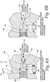
- FIG. 8A is a cross-sectional view of an illustrative pilot-operated directional valve as may be used in the system of FIG. 7 ;
- FIG. 8B is another cross-sectional view of an illustrative pilot-operated directional valve as may be used in the system of FIG. 7 ;
- FIG. 9 is a hydraulic schematic diagram of a further illustrative hydraulic stabilizing system configured to operate a plurality of hydraulically-operated stabilizing jacks according to the present disclosure.
- FIGS. 1-5 show an illustrative hydraulically-operated stabilizing system 10 or parts thereof according to the present disclosure.
- the system includes four stabilizing jacks 12 that may be installed on an RV, trailer, or other vehicle.
- the jacks 12 may be referred to herein individually as the first through fourth jacks 12 A- 12 D or the jacks 12 n and collectively as the jacks 12 n .
- the various components of the jacks 12 n may be referred to herein individually or collectively by appending their respective reference characters in a similar manner.
- the system 10 may include more or fewer than four jacks 12 n.
- each jack 12 n includes a base 14 configured for attachment to another structure, for example, an RV, a trailer, or another vehicle.
- the interior of the base 14 defines a channel 16 carrying a trunnion 18 .
- a linear hydraulic actuator 20 is connected to the base 14 .
- the actuator 20 is operably connected to the trunnion 18 and is configured to selectively displace the trunnion within the channel 16 .
- the trunnion 18 may be configured, for example, to slide within the channel 16 .
- the trunnion 18 may include wheels configured to roll within the channel 16 .
- Each jack 12 n also includes a strut (or struts) 22 pivotally connected to the base 14 , and a leg 24 having a first end and a second end.
- the first end of the leg 24 is operably connected to the trunnion 18 .
- the second end of the leg 24 may be connected to a foot 26 , pivotally (as shown) or otherwise.
- the strut 22 is pivotally connected to the leg 24 between the first end and the second end of the leg.
- the actuator 20 includes an actuator cylinder 28 having a first end and a second end, an actuator piston 30 slidably engaged within the actuator cylinder, and an actuator piston rod 32 connected to the actuator piston.
- the actuator piston rod 32 is extendable and retractable with respect to the actuator cylinder 28 through an end cap of the actuator cylinder in response to displacement of the actuator piston 30 within the actuator cylinder.
- extension of the actuator piston rod 32 from the actuator cylinder 28 would cause the leg 24 to articulate so that the second end of the leg (and the foot 26 connected thereto) extends from the base 14 , and that retraction of the actuator piston rod into the actuator cylinder would cause the leg to articulate so that the second end of the leg (and the foot connected thereto) retracts toward the base.
- the actuator cylinder 28 and the actuator piston 30 cooperate to define an actuator first chamber 38 (which may sometimes be referred to herein as the actuator extend chamber or the non-rod side of the actuator piston) and an actuator second chamber 40 (which may sometimes be referred to herein as the actuator retract chamber or the rod side of the actuator piston).
- a pilot-operated check valve 42 having first and second flow ports is connected to the actuator retract chamber 40 with the flow ports in fluid communication therewith.
- the pilot-operated check valve 42 further has a pilot port in fluid communication with a corresponding hydraulic extend line, as will be discussed further below.
- the actuator extend chamber 38 has a maximum volume defined by the interior of the actuator cylinder 28 and the free surface of the actuator piston 30 when the actuator piston rod 32 is fully extended from the actuator cylinder (or when the actuator piston is fully displaced toward the second end of the actuator cylinder).
- the actuator retract chamber 40 has a maximum volume defined by the interior of the actuator cylinder 28 , the surface of the actuator piston 30 to which the actuator piston rod 32 is attached, and the actuator piston rod when the actuator piston rod is fully retracted into the actuator cylinder (or when the actuator piston is fully displaced toward the first end of the actuator cylinder).
- An actuator volume ratio (or actuator rod head ratio) may be defined by the maximum actuator retract chamber volume divided by the maximum actuator extend chamber volume.
- the system 10 includes a fluid transfer pump 44 configured to selectively provide hydraulic fluid to, and selectively receive hydraulic fluid from the actuator extend chamber 38 and the actuator retract chamber 40 .
- the pump 44 includes a pump hydraulic cylinder 46 having a first end and a second end, a pump piston 48 slidably engaged within the pump cylinder, and a pump piston rod 50 connected to the pump piston.
- the pump cylinder 46 and the pump piston 48 cooperate to define a pump first chamber 52 (which may sometimes be referred to herein as the pump extend chamber or the non-rod side of the pump piston) and an actuator second chamber 54 (which may sometimes be referred to herein as the pump retract chamber or the rod side of the pump piston).
- the pump piston rod 50 is connected to and extends from one side (the rod side) of the pump piston 48 and through an end cap of the pump cylinder 46 .
- the pump piston rod 50 is connected to the pump piston 48 in a fluid-tight manner, for example, by a continuous weld.
- the pump piston rod 50 is extendable and retractable with respect to the pump cylinder 46 through an end cap of the pump cylinder in response to displacement of the pump piston 48 within the pump cylinder.
- the pump piston 48 defines a hole 56 extending axially therethrough and coaxial with the pump piston rod 50 .
- the hole 56 in the pump piston 48 is internally threaded and configured for threaded engagement with a drive screw 60 .
- the drive screw 60 is externally threaded and configured for threaded engagement with the internal threads of the hole 56 .
- the pump piston rod 50 defines a blind hole 58 extending partially and axially therethrough from the end thereof coextensive with the pump piston 48 .
- the blind hole 58 in the pump piston rod 50 communicates with the hole 56 in the pump piston 48 and with the pump extend chamber 52 .
- the free end of the drive screw 60 is embodied as (or fitted with) a drive head 61 , for example, a hex head, for engagement with an operator, for example, a hand tool or a power tool having a complementary head.
- a drive head 61 for example, a hex head
- the free end of the drive screw 60 or the drive head 61 could be connected to a bi-directional electric motor (not shown).
- the pump cylinder 46 and the pump piston 48 may have an oval or other non-round cross-section so that the pump piston is keyed to the pump cylinder in non-rotational engagement.
- the pump cylinder 46 and the pump piston 48 could have a round cross-section, and the pump piston rod 50 and the complementary opening in the end cap of the pump cylinder 46 could have complementary shapes.
- the pump cylinder 46 and the pump piston 48 could be keyed together in other ways.
- a pump extend chamber fill/bleed port 62 penetrates the pump cylinder 46 to allow selective fluid communication between the pump extend chamber 52 and the environment (which environment may include a receptacle for receiving hydraulic fluid bled from the pump extend chamber bleed port).
- a pump retract chamber bleed port 64 penetrates the pump cylinder 46 to allow selective fluid communication between the pump retract chamber 54 and the environment.
- the pump extend chamber 52 has a maximum volume defined by the interior of the pump cylinder 46 and the free surface of the pump piston 48 when the pump piston rod 50 is fully extended from the pump cylinder (that is, when the pump piston is fully displaced toward the second end of the pump cylinder).
- the pump retract chamber 44 has a maximum volume defined by the interior of the pump cylinder 46 , the surface of the pump piston 48 to which the pump piston rod 50 is attached, and the pump piston rod when the pump piston rod is fully retracted into the pump cylinder (that is, when the pump piston is fully displaced toward the first end of the pump cylinder).
- a pump volume ratio (or pump rod head ratio) may be defined by the maximum pump retract chamber 54 volume divided by the maximum pump extend chamber 52 volume.
- the pump volume ratio is substantially similar to the actuator volume ratio of the actuators 20 of all of the jacks 12 n collectively. More specifically, the pump extend chamber 52 volume may be substantially similar to the sum of the actuator extend chamber 38 volumes of the individual jacks 12 n , and the pump retract chamber 54 volume may be substantially similar to the sum of the actuator retract chamber 40 volumes of the individual jacks 12 n . In an embodiment wherein the actuators 20 of all of the individual jacks 12 n are identical, the pump volume ratio is substantially similar to the jack volume ratio of the individual actuators 20 of the jacks 12 n.
- the pump volume ratio may be greater than the jack volume ratio of the actuators 20 of the jack 12 n collectively.
- the pump retract chamber 54 volume would be greater than the sum of the actuator retract chamber 40 volumes of the actuators 20 of the individual jacks 12 n
- the pump extend chamber 52 volume of the pump would be lesser than the sum of the actuator extend chamber 38 volumes of the actuators of the individual jacks.
- over-retraction of the pump piston rod 50 could result in vacuum being drawn in the pump retract chamber 54 , thus causing the hydraulic fluid therein and/or in the corresponding actuator retract chambers 40 (and/or in the corresponding retract lines connecting the pump retract chamber with the actuator retract chambers, as will be discussed below) to displace entrained air or “boil.”
- even full extension of the pump piston rod 50 may fail to transfer sufficient hydraulic fluid from the pump extend chamber 52 to the actuator extend chambers 38 of the actuators 20 of all of the jacks 12 n to fully extend the actuator piston rods 32 thereof.
- the pump volume ratio may be lesser than the jack volume ratio of the actuators 20 of the jacks 12 n collectively.
- the pump extend chamber 52 volume would be greater than the sum of the actuator extend chamber 38 volumes of the actuators 20 of the individual jacks 12 n
- the pump retract chamber 54 volume would be lesser than the sum of the actuator retract chamber 40 volumes of the actuators 20 of the individual jacks.
- the pump extend chamber 52 may contain a substantial amount of surplus hydraulic fluid, even when the actuator extend chambers 38 of the actuators 20 of all of the jacks 12 n are completely filled with hydraulic fluid.
- the system 10 may be configured so that the actuators 20 of the first and second jacks 12 A, 12 B are controlled by a first hydraulic circuit, and so that actuators of the third and fourth jacks 12 C, 12 D are controlled by a second hydraulic circuit.
- the first hydraulic circuit includes a first hydraulic circuit extend line 66 connecting the pump extend chamber 52 with the respective extend chambers 38 of the actuators 20 of the first and second jack actuators 12 A, 12 B, with the respective pilot ports of the pilot-operated check valves 42 of the first and second jack actuators, and with a first extend line bleed port 68 in fluid communication.
- the first extend line bleed port 68 may be opened and closed using a removable cap or a bleed valve to facilitate filling and bleeding of the first hydraulic circuit. As shown in FIG.
- the first hydraulic circuit extend line 66 may be provided in segments, with a first segment 66 A connecting the pump extend chamber 52 with the extend chamber 38 of the actuator 20 of the second jack actuator 12 B, a second segment 66 B connecting the extend chamber 38 of the actuator 20 of the second jack 12 B with the extend chamber 38 of the actuator 20 of the first jack 12 A and with the pilot port of the pilot-operated check valve 42 of the actuator 20 of the second jack 12 B, and a third segment 66 C connecting the extend chamber 38 of the actuator 20 of the first jack 12 A with the pilot port of the pilot-operated check valve 42 of the first jack 12 A and also with the first extend line bleed port 68 .
- the first hydraulic circuit extend line 66 may interconnect the foregoing components in any suitable manner.
- the first hydraulic circuit also includes a first hydraulic retract line 70 connecting the pump retract chamber 54 with respective flow ports of the pilot-operated check valves 42 of the first and second jack actuators 12 A, 12 B and with a first retract line bleed port 72 in fluid communication.
- the second hydraulic circuit includes analogous second hydraulic circuit extend and second hydraulic circuit retract lines hydraulically coupling the pump 44 with the actuators 20 of the third and fourth jacks 12 C, 12 D in an analogous manner.
- analogous extend and retract lines and other analogous hydraulic system components are identified using primed reference characters corresponding to those used above in connection with the first hydraulic circuit.
- rotation of the drive screw 60 in a first direction causes the pump piston 48 to be displaced so as to force hydraulic fluid from the pump extend chamber 52 into the first and second hydraulic circuit extend lines and the extend chamber 38 of each of the actuators 20 n .
- the fluid pressure in the extend portion of the system may be below the set point pressure of the pilot-operated check valve 42 of any or all of the actuators 20 n . If so, the respective pilot-operated check valve 42 n checks flow out of the respective actuator retract chamber 40 n , thereby precluding displacement of the respective actuator piston 30 n.
- the actuator piston 28 of one of the first and second jacks 12 A, 12 B may bottom out in the respective actuator cylinder 28 before the actuator piston of the other of the first and second jacks bottoms out in the respective actuator cylinder. Because the extend chambers 38 of the first and second actuators 20 A, 20 B are connected together in fluid communication, the actuator piston 30 of the other of the first and second jack actuators can continue to extend until it, too, bottoms out.
- Rotation of the drive screw 60 in a second direction causes the pump piston 48 to be displaced so as to force fluid out of the pump retract chamber 54 into the corresponding retract lines and into the actuator retract chambers 40 of each of the actuators 20 . Consequently, the actuator piston 30 is displaced so as to force hydraulic fluid out of the actuator extend chamber 40 , and the actuator piston rod 32 retracts into the respective actuator cylinder 28 , thereby extending the leg 24 of the jack 12 away from the base 14 of the jack.
- the plugs of the pilot-operated check valves 42 engage with their seats and check discharge of hydraulic fluid from the jack retract chambers 40 .
- the leg 24 of one of the first and second jacks 12 A, 12 B may bear against the ground before the leg of the other of the first and second jacks bears against the ground. Because the retract chambers 40 of the first and second actuators 20 A, 20 B are connected together in fluid communication, the leg 24 of the other of the first and second jack actuators 12 A, 12 B can continue to extend until it, too, bears against the ground. When the legs 24 of both the first and second jacks 12 A, 12 B have come into bearing against the ground, further displacement of the corresponding actuator pistons 30 is inhibited.
- the third and fourth actuators 20 C, 20 D behave in a manner similar to the first and second actuators 20 A, 20 B.
- FIGS. 6-8 show another illustrative hydraulic stabilizing system 110 according to the present disclosure.
- the system includes four stabilizing jacks 112 that may be installed on an RV, trailer, or other vehicle.
- the jacks 112 may be referred to herein individually as the first through fourth jacks 112 A- 112 D or the jacks 112 n and collectively as the jacks 112 n .
- the various components of the jacks 112 n may be referred to herein individually or collectively by appending their respective reference characters in a similar manner.
- the system 110 may include more or fewer than four jacks 112 n.
- FIG. 6 shows an illustrative jack 112 .
- the jack 112 is in most respects identical or analogous to the jack 12 described above.
- the components of the jack 112 that have identical or analogous counterparts in the jack 12 may be identified herein by like reference numbers, incremented by 100, and generally will not be discussed further. As such, the following discussion of the jack 112 generally is directed to differences between the jack 112 and the jack 12 .
- the jack 112 may further include a biasing element 113 configured to bias the leg 122 of the jack to a retracted position.
- the biasing member 113 may be embodied as a helical tension spring connected between the base 114 and the trunnion 116 of the jack 112 . In other embodiments, the biasing element 113 may be embodied in other ways.
- the actuator 120 of the jack 112 differs in some regards from the actuator 20 of the jack 12 .
- the components of the actuator 120 that have identical or analogous counterparts in the actuator 20 may be identified herein by like reference numbers, incremented by 100, and generally will not be discussed further. As such, the following discussion of the actuator 120 generally is directed to differences between the actuator 120 and the actuator 20 .
- the non-rod side 138 of the actuator 120 need not be plumbed to receive or reject hydraulic fluid as is the non-rod side 38 of the actuator 20 .
- the non-rod side 138 of the actuator 120 includes a biasing element 178 , for example, a coil extension spring, acting against the non-rod side end of the actuator cylinder 128 and the non-rod side of the actuator piston 130 .
- the biasing element 178 biases the actuator piston 130 toward the rod-side end of the actuator cylinder.
- the biasing element 178 could be compressed gas, for example, compressed air, sealed within the actuator extend chamber 138 , or within a sealed container (not shown) disposed within the actuator extend chamber.
- the actuator 120 does not include a pilot-operated check valve as does the actuator 20 . Instead, the actuator 120 includes a pilot-operated directional valve 176 .
- FIGS. 8A and 8B show an illustrative pilot-operated directional valve 176 including a first flow port 180 connected to the retract line 170 and a second flow port 182 connected to the corresponding actuator retract chamber 140 .
- the valve 176 also includes a ball or plug 184 selectively engageable with a valve seat 186 .
- the plug 184 may be selectively mechanically displaced off the valve seat 186 by an operator including a rod 188 connected to an operator piston 190 slidingly received within a bore 192 in the body of the valve 176 .
- An O-ring 194 may be provided in connection with the piston 190 and the bore to effect a fluid-tight seal therebetween.
- the O-ring 194 may be disposed in a groove defined by the outer circumference of the piston 190 .
- a biasing spring 196 may be disposed between a face of the non-rod side of the piston 190 and a bearing surface 198 .
- the biasing spring 196 is configured to bias the piston 190 and the attached rod 188 toward a first position in which the rod precludes the plug 184 from engaging with the seat 186 .
- the biasing force provided by the biasing spring 196 may be overcome by sufficient fluid pressure (the pilot-operated directional control valve setpoint pressure) in the corresponding retract line 170 applied to the rod side of the piston 190 so as to displace the piston and the rod 188 toward a second position in which the rod does not preclude the plug from engaging with the seat 186 .
- hydraulic fluid may flow between the retract line 170 and the actuator retract chamber 140 in both directions.
- hydraulic fluid may flow from the retract line 170 to the actuator retract chamber 140 , but not in the opposite direction.
- rotation of the drive screw 160 in a first direction causes the pump piston 148 to be displaced so as to draw hydraulic fluid from the actuator retract chambers 140 of the jacks 112 A 112 D through the corresponding retract lines 170 and into the pump retract chamber 154 .
- the check valve piston 190 and rod 188 of each of the jacks 112 A ⁇ 112 D initially will be in the second position and the corresponding plugs 184 may be engaged with the corresponding seats 186 .
- the foregoing operation of the drive screw 152 will reduce the fluid pressure in the retract lines 170 to a pressure below the setpoint pressure.
- the biasing springs 196 will displace the pistons 190 and the rods 188 to the first position, thereby disengaging the plugs 184 from the seats 186 and enabling flow of hydraulic fluid from the actuator retract chambers 140 of each of the jacks 112 A 112 D, through the retract lines 170 , and into the pump retract chamber 154 .
- the biasing elements 138 and the reduced pressure in the actuator retract chambers cooperate to extend the actuator piston rods 132 from the actuator cylinders 128 and, therefore, to retract the jack legs 122 toward the jack bases 114 .
- the third and fourth jacks 112 C, 112 D operate in a similar manner.
- the pump 144 is similar to the pump 44 except that the non-rod side 152 of the pump 144 is not plumbed to receive or reject hydraulic fluid 44 (the non-rod side of the pump 144 may be referred to herein as the dry side or dry chamber, and the rod side of the pump 144 may be referred to herein as the fluid side or fluid chamber).
- the dry and fluid chambers of the pump 144 could be reversed. That is, the fluid chamber of the pump 144 could be on the non-rod side of the pump piston 148 , and the dry chamber 142 could be on the rod side of the pump piston.
- FIG. 9 shows a further illustrative hydraulic stabilizing system 210 according to the present disclosure.
- the system 210 is substantially similar to the system 110 in most regards.
- Features of the system 210 having direct counterparts in the system 110 are identified herein using like reference characters, incremented by 100.
- the system 210 as shown includes four stabilizing jacks 212 similar or identical to the jacks 112 of the system 110 .
- the system 210 differs from the system 110 primarily in that the pump 244 of the system 210 is embodied as a reciprocating hand pump, whereas the pump 144 of the system 110 is embodied as a screw-operated pump.
- the pump 244 includes a pump hydraulic cylinder 246 having a first end and a second end, a pump piston 248 slidably engaged within the pump cylinder, and a pump piston rod 250 connected to the pump piston.
- the pump cylinder 246 and the pump piston 248 cooperate to define a pump first chamber 252 (which may sometimes be referred to herein as the pump dry chamber or the rod side of the pump piston) and a pump second chamber 254 (which may sometimes be referred to herein as the pump fluid chamber or the non-rod side of the pump piston).
- the pump piston rod 250 is connected to and extends from one side (the rod side) of the pump piston 248 .
- the pump piston rod 250 is extendable and retractable with respect to the pump cylinder 246 in response to displacement of a reciprocating pump actuator 251 .
- the pump 244 also includes a fluid reservoir 245 , a first check valve 247 enabling selective fluid communication between the reservoir and the fluid chamber 254 , a second check valve 249 enabling selective fluid communication between the fluid chamber and the retract chambers 240 of the actuators 212 n , and a fluid control valve 253 enabling selective fluid communication between the retract chambers of the actuators and the reservoir.
- a user may operate the pump 244 by operating the reciprocating pump actuator 251 to withdraw the piston rod 250 from the cylinder 246 , thereby moving the piston 248 so as to increase the volume of the fluid chamber 254 , thereby decreasing the pressure in the fluid chamber.
- the pressure reduction tends to close or cause to remain closed the second check valve 249 to draw fluid from the reservoir 245 through the first check valve 247 into the fluid chamber 254 .
- the user may further operate the reciprocating actuator 251 to retract the piston rod 250 into the cylinder 246 , thereby moving the piston 248 so as to decrease the volume of the fluid chamber 254 , thereby increasing the pressure in the fluid chamber.
- the pressure increase tends to close or cause to remain closed the first check valve 247 and to force fluid from the fluid chamber 254 , through the second check valve 249 , and into the retract chambers 240 of the actuators.
- the user may continue to operate the reciprocating actuator 251 as may be necessary to achieve a desired state of retraction of the actuator pistons 230 and actuator piston rods 232 into the actuator cylinders 228 .
- the user may open the control valve 253 to relieve fluid from the retract chambers 240 of the actuators 212 n to the reservoir 245 .
- extension of the actuator piston rod 32 , 132 , 232 causes the leg 24 , 124 , 224 , of the jack 12 , 112 , 212 to retract, and retraction of the actuator piston rod causes the leg of the jack to extend.
- this relationship could be reversed.
- the actuator 20 , 120 , 220 could be mounted to the base 14 , 114 , 214 of the jacks 12 , 112 , 212 so as to act on the opposite side of the trunnions 18 , 118 , 218 .
- the flow ports of the pilot-operated check valves 42 of the jack actuators 12 n would be connected to the extend chambers 38 of the jack actuators and the corresponding extend lines, and the pilot ports of the pilot-operated check valves would be connected to the retract lines 70 in a reversal of the arrangement shown and described above.
- the hydraulic pump 144 , 244 would communicate hydraulic fluid with the actuator extend chambers 138 , 238 instead of with the actuator retract chambers.
- the flow ports of the pilot-operated directional valves 176 , 276 of the actuators 120 n , 220 n would be connected to the actuator extend chambers 138 , 238 and to corresponding extend lines, and the pilot ports of the pilot-operated directional check valves would be connected to the extend lines in a reversal of the arrangement shown and described above.
- the actuators 20 n , 120 n , 220 n themselves could function as the jacks. More specifically, each of the actuators 20 n , 120 n , 220 n could be mounted to the vehicle with the respective actuator cylinder 28 , 128 , 228 , actuator piston 30 , 130 , 230 , and actuator piston rod 32 , 132 , 232 oriented vertically. A foot (not shown) could be attached to the free end of the actuator piston rod 30 , 132 , 232 .
- the flow ports of the pilot-operated valves 26 , 176 , 276 of the actuators 20 n , 120 n , 220 n would be connected to the actuator extend chambers 38 , 138 , 238 and to the corresponding extend lines, and the pilot ports of the pilot-operated check valves 26 (in embodiments using them) would be connected to the retract lines in a reversal of the arrangement shown and described above.
- the illustrated embodiments of the systems 10 , 110 , 210 include four stabilizing jacks 12 n , 112 n , 212 n . Other embodiments could include more or fewer than four stabilizing jacks 12 n , 112 n , 212 n . Also, the illustrated embodiments of the systems 10 , 110 include two hydraulic circuits. Other embodiments could include more or fewer than two hydraulic circuits.
- the hydraulic circuit is configured to allow equalization of pressure at each of the actuators 20 n , 120 n , 220 n .
- This feature may inhibit any single jack 12 n , 112 n , 212 n from taking on a disproportionate load that could cause the vehicle's frame to twist.
Landscapes
- Engineering & Computer Science (AREA)
- Mechanical Engineering (AREA)
- Physics & Mathematics (AREA)
- Fluid Mechanics (AREA)
- Fluid-Pressure Circuits (AREA)
- Health & Medical Sciences (AREA)
- Public Health (AREA)
- Transportation (AREA)
Abstract
Description
Claims (17)
Priority Applications (6)
| Application Number | Priority Date | Filing Date | Title |
|---|---|---|---|
| US15/912,030 US10688972B2 (en) | 2017-03-29 | 2018-03-05 | Manually-operable hydraulic stabilizing system |
| AU2018217324A AU2018217324A1 (en) | 2018-03-05 | 2018-08-17 | Manually-operable hydraulic stabilizing system |
| EP18190174.5A EP3536565A1 (en) | 2018-03-05 | 2018-08-22 | Hydraulic stabilizing system |
| US16/196,949 US10442411B2 (en) | 2017-03-29 | 2018-11-20 | Manually-operable hydraulic stabilizing system |
| US16/541,220 US11052878B2 (en) | 2017-03-29 | 2019-08-15 | Manually-operable hydraulic stabilizing system |
| US17/366,201 US20210339717A1 (en) | 2017-03-29 | 2021-07-02 | Manually-operable hydraulic stabilizing system |
Applications Claiming Priority (3)
| Application Number | Priority Date | Filing Date | Title |
|---|---|---|---|
| US201762478271P | 2017-03-29 | 2017-03-29 | |
| US201762513766P | 2017-06-01 | 2017-06-01 | |
| US15/912,030 US10688972B2 (en) | 2017-03-29 | 2018-03-05 | Manually-operable hydraulic stabilizing system |
Related Child Applications (1)
| Application Number | Title | Priority Date | Filing Date |
|---|---|---|---|
| US16/196,949 Continuation-In-Part US10442411B2 (en) | 2017-03-29 | 2018-11-20 | Manually-operable hydraulic stabilizing system |
Publications (2)
| Publication Number | Publication Date |
|---|---|
| US20180281755A1 US20180281755A1 (en) | 2018-10-04 |
| US10688972B2 true US10688972B2 (en) | 2020-06-23 |
Family
ID=63672867
Family Applications (1)
| Application Number | Title | Priority Date | Filing Date |
|---|---|---|---|
| US15/912,030 Expired - Fee Related US10688972B2 (en) | 2017-03-29 | 2018-03-05 | Manually-operable hydraulic stabilizing system |
Country Status (1)
| Country | Link |
|---|---|
| US (1) | US10688972B2 (en) |
Cited By (2)
| Publication number | Priority date | Publication date | Assignee | Title |
|---|---|---|---|---|
| US11014541B2 (en) * | 2018-04-09 | 2021-05-25 | Airman Products, Llc | Semi-trailer landing gear actuator |
| US11052878B2 (en) * | 2017-03-29 | 2021-07-06 | Lippert Components, Inc. | Manually-operable hydraulic stabilizing system |
Families Citing this family (3)
| Publication number | Priority date | Publication date | Assignee | Title |
|---|---|---|---|---|
| CN109760159B (en) * | 2019-01-22 | 2021-05-11 | 宁夏德琴农业科技开发有限公司 | Straw supporting pad forming machine |
| EP3786009B1 (en) * | 2019-08-30 | 2024-01-10 | EWO Fluid Power GmbH | Hydraulically actuatable support device on a vehicle or on a vehicle body |
| CN115818473A (en) * | 2022-11-25 | 2023-03-21 | 杭州爱知工程车辆有限公司 | Engineering vehicle landing leg device |
Citations (28)
| Publication number | Priority date | Publication date | Assignee | Title |
|---|---|---|---|---|
| US2165285A (en) * | 1937-12-27 | 1939-07-11 | Blackhawk Mfg Co | Spring perch and brake bracket remover |
| US3767226A (en) * | 1972-03-24 | 1973-10-23 | J Stephens | Stabilizer for vehicle |
| US3788173A (en) | 1972-12-15 | 1974-01-29 | R Keigley | Hydraulic hand tool |
| US3801068A (en) * | 1972-12-22 | 1974-04-02 | Kogen Ind Inc | Automatic folding landing gear |
| US4025085A (en) | 1975-12-31 | 1977-05-24 | James Paul Jacobs | Sway stabilizer for trailing vehicles |
| GB2066188A (en) | 1979-11-24 | 1981-07-08 | Nichols P W | Trailer jacking system |
| US4784400A (en) * | 1987-02-09 | 1988-11-15 | Hofius Walter E | Vehicle leveling and stabilizing apparatus |
| US4865295A (en) | 1987-06-17 | 1989-09-12 | Holloway Lowell E | Holloway's self-deploying stabilizing jack |
| US4887359A (en) | 1987-02-09 | 1989-12-19 | Hofius Walter E | Vehicle leveling and stabilizing apparatus |
| US5013011A (en) | 1987-06-17 | 1991-05-07 | Halloway Lowell E | Self-deploying stabilizing jack |
| US5221100A (en) | 1992-07-16 | 1993-06-22 | Mcnutt Darrell A | Trailer frame with stabilized caster swivel |
| US5451076A (en) * | 1993-12-20 | 1995-09-19 | New Way Corporation | Pneumatic trailer landing gear |
| US6098996A (en) | 1998-09-18 | 2000-08-08 | Smc Corporation | Carrier leveling and stabilizing system |
| US6237904B1 (en) | 1999-02-10 | 2001-05-29 | John D. Shepherd | Motion stabilizer |
| US6318508B1 (en) * | 1999-06-25 | 2001-11-20 | Tsubakimoto Chain Co. | Elevating system control method and apparatus synchronizing plural elevating devices |
| US6634461B1 (en) * | 2002-06-10 | 2003-10-21 | Gray Automotive Products, Inc. | Coordinated lift system |
| US6695348B2 (en) | 2000-09-05 | 2004-02-24 | Richard J. Holly | RV stabilizer |
| US6698777B1 (en) | 2002-11-27 | 2004-03-02 | John D. Shepherd | Dynamically adjustable motion stabilizer |
| US20050067227A1 (en) * | 2003-09-26 | 2005-03-31 | Wengelski Jason D. | Level elevating stabilizing system |
| US6880854B2 (en) | 2002-05-30 | 2005-04-19 | Deere & Company | Stabilizing weight assemblies for tractors |
| US7624995B2 (en) | 2002-09-27 | 2009-12-01 | Ride Control, Llc | Suspension with integrated leveling and stabilization mechanisms |
| US20150128360A1 (en) * | 2013-11-11 | 2015-05-14 | Grant Leum | Mobile Loading Dock with Adjustable Leg Assembly |
| US20150129821A1 (en) * | 2013-11-14 | 2015-05-14 | Lippert Components Manufacturing, Inc. | Swing-down jack with locks |
| US9701285B2 (en) | 2015-01-29 | 2017-07-11 | Lippert Components, Inc. | Locking stabilizer jack |
| US10093286B2 (en) | 2015-01-15 | 2018-10-09 | Quadra Manufacturing, Inc. | Timer based vehicle leveling and stabilization system and method of manufacture |
| US10160278B2 (en) | 2014-12-16 | 2018-12-25 | Aktv8 LLC | System and method for vehicle stabilization |
| US10167178B2 (en) | 2015-03-27 | 2019-01-01 | Lippert Components, Inc. | Leveling jack with direct actuation |
| US10442411B2 (en) * | 2017-03-29 | 2019-10-15 | Lippert Components, Inc. | Manually-operable hydraulic stabilizing system |
-
2018
- 2018-03-05 US US15/912,030 patent/US10688972B2/en not_active Expired - Fee Related
Patent Citations (29)
| Publication number | Priority date | Publication date | Assignee | Title |
|---|---|---|---|---|
| US2165285A (en) * | 1937-12-27 | 1939-07-11 | Blackhawk Mfg Co | Spring perch and brake bracket remover |
| US3767226A (en) * | 1972-03-24 | 1973-10-23 | J Stephens | Stabilizer for vehicle |
| US3788173A (en) | 1972-12-15 | 1974-01-29 | R Keigley | Hydraulic hand tool |
| US3801068A (en) * | 1972-12-22 | 1974-04-02 | Kogen Ind Inc | Automatic folding landing gear |
| US4025085A (en) | 1975-12-31 | 1977-05-24 | James Paul Jacobs | Sway stabilizer for trailing vehicles |
| GB2066188A (en) | 1979-11-24 | 1981-07-08 | Nichols P W | Trailer jacking system |
| US4784400A (en) * | 1987-02-09 | 1988-11-15 | Hofius Walter E | Vehicle leveling and stabilizing apparatus |
| US4887359A (en) | 1987-02-09 | 1989-12-19 | Hofius Walter E | Vehicle leveling and stabilizing apparatus |
| US4865295A (en) | 1987-06-17 | 1989-09-12 | Holloway Lowell E | Holloway's self-deploying stabilizing jack |
| US5013011A (en) | 1987-06-17 | 1991-05-07 | Halloway Lowell E | Self-deploying stabilizing jack |
| US5221100A (en) | 1992-07-16 | 1993-06-22 | Mcnutt Darrell A | Trailer frame with stabilized caster swivel |
| US5451076A (en) * | 1993-12-20 | 1995-09-19 | New Way Corporation | Pneumatic trailer landing gear |
| US6098996A (en) | 1998-09-18 | 2000-08-08 | Smc Corporation | Carrier leveling and stabilizing system |
| US6237904B1 (en) | 1999-02-10 | 2001-05-29 | John D. Shepherd | Motion stabilizer |
| US6318508B1 (en) * | 1999-06-25 | 2001-11-20 | Tsubakimoto Chain Co. | Elevating system control method and apparatus synchronizing plural elevating devices |
| US6695348B2 (en) | 2000-09-05 | 2004-02-24 | Richard J. Holly | RV stabilizer |
| US6880854B2 (en) | 2002-05-30 | 2005-04-19 | Deere & Company | Stabilizing weight assemblies for tractors |
| US6634461B1 (en) * | 2002-06-10 | 2003-10-21 | Gray Automotive Products, Inc. | Coordinated lift system |
| US7624995B2 (en) | 2002-09-27 | 2009-12-01 | Ride Control, Llc | Suspension with integrated leveling and stabilization mechanisms |
| US6698777B1 (en) | 2002-11-27 | 2004-03-02 | John D. Shepherd | Dynamically adjustable motion stabilizer |
| US20050067227A1 (en) * | 2003-09-26 | 2005-03-31 | Wengelski Jason D. | Level elevating stabilizing system |
| US7025178B2 (en) | 2003-09-26 | 2006-04-11 | Actuant Corporation | Stabilizing system for orienting and elevating a vehicle |
| US20150128360A1 (en) * | 2013-11-11 | 2015-05-14 | Grant Leum | Mobile Loading Dock with Adjustable Leg Assembly |
| US20150129821A1 (en) * | 2013-11-14 | 2015-05-14 | Lippert Components Manufacturing, Inc. | Swing-down jack with locks |
| US10160278B2 (en) | 2014-12-16 | 2018-12-25 | Aktv8 LLC | System and method for vehicle stabilization |
| US10093286B2 (en) | 2015-01-15 | 2018-10-09 | Quadra Manufacturing, Inc. | Timer based vehicle leveling and stabilization system and method of manufacture |
| US9701285B2 (en) | 2015-01-29 | 2017-07-11 | Lippert Components, Inc. | Locking stabilizer jack |
| US10167178B2 (en) | 2015-03-27 | 2019-01-01 | Lippert Components, Inc. | Leveling jack with direct actuation |
| US10442411B2 (en) * | 2017-03-29 | 2019-10-15 | Lippert Components, Inc. | Manually-operable hydraulic stabilizing system |
Non-Patent Citations (1)
| Title |
|---|
| European Search Report dated Mar. 14, 2019 issued in European Patent Application No. 18190174.5, 8 pp. |
Cited By (3)
| Publication number | Priority date | Publication date | Assignee | Title |
|---|---|---|---|---|
| US11052878B2 (en) * | 2017-03-29 | 2021-07-06 | Lippert Components, Inc. | Manually-operable hydraulic stabilizing system |
| US20210339717A1 (en) * | 2017-03-29 | 2021-11-04 | Lippert Components, Inc. | Manually-operable hydraulic stabilizing system |
| US11014541B2 (en) * | 2018-04-09 | 2021-05-25 | Airman Products, Llc | Semi-trailer landing gear actuator |
Also Published As
| Publication number | Publication date |
|---|---|
| US20180281755A1 (en) | 2018-10-04 |
Similar Documents
| Publication | Publication Date | Title |
|---|---|---|
| US10688972B2 (en) | Manually-operable hydraulic stabilizing system | |
| US20210339717A1 (en) | Manually-operable hydraulic stabilizing system | |
| US8070095B2 (en) | Shrinking shock strut system for retractable landing gear | |
| US10442411B2 (en) | Manually-operable hydraulic stabilizing system | |
| US20110024706A1 (en) | Leveling jack for vehicle | |
| US6345564B1 (en) | Semi-levered landing gear and auxiliary strut thereof | |
| US20100219290A1 (en) | Electric-powered transfer cylinder for landing gear system | |
| CN102530243B (en) | Hydraulic actuators for semi-lever landing gear | |
| US3472547A (en) | Safety tilt system | |
| US3801151A (en) | Double-acting lift cylinder with integral velocity fuses | |
| US3972557A (en) | Hydraulic cab-tilting systems | |
| RU2652869C2 (en) | Active semi-levered landing gear | |
| MXPA03001446A (en) | Remotely actuated multiple pressure direct acting relief valve. | |
| US20170363120A1 (en) | Cushion mechanism for a hydraulic cylinder | |
| US20110018219A1 (en) | Hydraulic, rigid rear axle suspension system for vehicles | |
| AU2020213399B2 (en) | Manually-Operable Hydraulic Stabilizing System | |
| DE1630058B1 (en) | Hydropneumatic strut with internal level control device | |
| US3442502A (en) | Air spring suspension for vehicles | |
| US11565798B2 (en) | Center biased actuator | |
| EP3536565A1 (en) | Hydraulic stabilizing system | |
| US5611646A (en) | Support prop with integrated pressure limiting valve and nailed pipes | |
| US20190118882A1 (en) | Hydraulic operating system for trailer axle | |
| EP2343223B1 (en) | Leveling jack for vehicle | |
| US8668038B2 (en) | Hydraulic cab tilt actuator with lost motion | |
| US3322393A (en) | Hydro-pneumatic shock absorber and jacking device |
Legal Events
| Date | Code | Title | Description |
|---|---|---|---|
| FEPP | Fee payment procedure |
Free format text: ENTITY STATUS SET TO UNDISCOUNTED (ORIGINAL EVENT CODE: BIG.); ENTITY STATUS OF PATENT OWNER: LARGE ENTITY |
|
| AS | Assignment |
Owner name: LIPPERT COMPONENTS, INC., INDIANA Free format text: ASSIGNMENT OF ASSIGNORS INTEREST;ASSIGNORS:KINDER, MARK;TIEDGE, ROBERT L.;SIGNING DATES FROM 20180409 TO 20180412;REEL/FRAME:046289/0592 |
|
| STPP | Information on status: patent application and granting procedure in general |
Free format text: DOCKETED NEW CASE - READY FOR EXAMINATION |
|
| STPP | Information on status: patent application and granting procedure in general |
Free format text: NON FINAL ACTION MAILED |
|
| AS | Assignment |
Owner name: LIPPERT COMPONENTS, INC., INDIANA Free format text: ASSIGNMENT OF ASSIGNORS INTEREST;ASSIGNOR:CORNETT, NICHOLAS;REEL/FRAME:051581/0155 Effective date: 20191115 |
|
| STPP | Information on status: patent application and granting procedure in general |
Free format text: RESPONSE TO NON-FINAL OFFICE ACTION ENTERED AND FORWARDED TO EXAMINER |
|
| STPP | Information on status: patent application and granting procedure in general |
Free format text: NOTICE OF ALLOWANCE MAILED -- APPLICATION RECEIVED IN OFFICE OF PUBLICATIONS |
|
| STPP | Information on status: patent application and granting procedure in general |
Free format text: PUBLICATIONS -- ISSUE FEE PAYMENT RECEIVED |
|
| STCF | Information on status: patent grant |
Free format text: PATENTED CASE |
|
| FEPP | Fee payment procedure |
Free format text: MAINTENANCE FEE REMINDER MAILED (ORIGINAL EVENT CODE: REM.); ENTITY STATUS OF PATENT OWNER: LARGE ENTITY |
|
| LAPS | Lapse for failure to pay maintenance fees |
Free format text: PATENT EXPIRED FOR FAILURE TO PAY MAINTENANCE FEES (ORIGINAL EVENT CODE: EXP.); ENTITY STATUS OF PATENT OWNER: LARGE ENTITY |
|
| STCH | Information on status: patent discontinuation |
Free format text: PATENT EXPIRED DUE TO NONPAYMENT OF MAINTENANCE FEES UNDER 37 CFR 1.362 |
|
| FP | Lapsed due to failure to pay maintenance fee |
Effective date: 20240623 |