US10686480B2 - Mobile terminal - Google Patents
Mobile terminal Download PDFInfo
- Publication number
- US10686480B2 US10686480B2 US16/473,959 US201616473959A US10686480B2 US 10686480 B2 US10686480 B2 US 10686480B2 US 201616473959 A US201616473959 A US 201616473959A US 10686480 B2 US10686480 B2 US 10686480B2
- Authority
- US
- United States
- Prior art keywords
- mobile terminal
- opening
- card
- cover part
- cover
- Prior art date
- Legal status (The legal status is an assumption and is not a legal conclusion. Google has not performed a legal analysis and makes no representation as to the accuracy of the status listed.)
- Active
Links
Images


Classifications
-
- G—PHYSICS
- G06—COMPUTING OR CALCULATING; COUNTING
- G06K—GRAPHICAL DATA READING; PRESENTATION OF DATA; RECORD CARRIERS; HANDLING RECORD CARRIERS
- G06K7/00—Methods or arrangements for sensing record carriers, e.g. for reading patterns
- G06K7/0013—Methods or arrangements for sensing record carriers, e.g. for reading patterns by galvanic contacts, e.g. card connectors for ISO-7816 compliant smart cards or memory cards, e.g. SD card readers
- G06K7/0034—Methods or arrangements for sensing record carriers, e.g. for reading patterns by galvanic contacts, e.g. card connectors for ISO-7816 compliant smart cards or memory cards, e.g. SD card readers the connector being capable of simultaneously receiving a plurality of cards in the same insertion slot
-
- H—ELECTRICITY
- H04—ELECTRIC COMMUNICATION TECHNIQUE
- H04M—TELEPHONIC COMMUNICATION
- H04M1/00—Substation equipment, e.g. for use by subscribers
- H04M1/02—Constructional features of telephone sets
- H04M1/0202—Portable telephone sets, e.g. cordless phones, mobile phones or bar type handsets
-
- G—PHYSICS
- G06—COMPUTING OR CALCULATING; COUNTING
- G06K—GRAPHICAL DATA READING; PRESENTATION OF DATA; RECORD CARRIERS; HANDLING RECORD CARRIERS
- G06K7/00—Methods or arrangements for sensing record carriers, e.g. for reading patterns
- G06K7/0013—Methods or arrangements for sensing record carriers, e.g. for reading patterns by galvanic contacts, e.g. card connectors for ISO-7816 compliant smart cards or memory cards, e.g. SD card readers
- G06K7/0021—Methods or arrangements for sensing record carriers, e.g. for reading patterns by galvanic contacts, e.g. card connectors for ISO-7816 compliant smart cards or memory cards, e.g. SD card readers for reading/sensing record carriers having surface contacts
-
- H—ELECTRICITY
- H04—ELECTRIC COMMUNICATION TECHNIQUE
- H04B—TRANSMISSION
- H04B1/00—Details of transmission systems, not covered by a single one of groups H04B3/00 - H04B13/00; Details of transmission systems not characterised by the medium used for transmission
- H04B1/38—Transceivers, i.e. devices in which transmitter and receiver form a structural unit and in which at least one part is used for functions of transmitting and receiving
- H04B1/3816—Mechanical arrangements for accommodating identification devices, e.g. cards or chips; with connectors for programming identification devices
- H04B1/3818—Arrangements for facilitating insertion or removal of identification devices
-
- H—ELECTRICITY
- H04—ELECTRIC COMMUNICATION TECHNIQUE
- H04M—TELEPHONIC COMMUNICATION
- H04M1/00—Substation equipment, e.g. for use by subscribers
- H04M1/02—Constructional features of telephone sets
- H04M1/0202—Portable telephone sets, e.g. cordless phones, mobile phones or bar type handsets
- H04M1/0206—Portable telephones comprising a plurality of mechanically joined movable body parts, e.g. hinged housings
- H04M1/0208—Portable telephones comprising a plurality of mechanically joined movable body parts, e.g. hinged housings characterized by the relative motions of the body parts
- H04M1/0235—Slidable or telescopic telephones, i.e. with a relative translation movement of the body parts; Telephones using a combination of translation and other relative motions of the body parts
- H04M1/0237—Sliding mechanism with one degree of freedom
-
- H—ELECTRICITY
- H04—ELECTRIC COMMUNICATION TECHNIQUE
- H04M—TELEPHONIC COMMUNICATION
- H04M1/00—Substation equipment, e.g. for use by subscribers
- H04M1/02—Constructional features of telephone sets
- H04M1/0202—Portable telephone sets, e.g. cordless phones, mobile phones or bar type handsets
- H04M1/026—Details of the structure or mounting of specific components
Definitions
- Embodiments of the present disclosure relate to a mobile terminal having a card tray.
- Terminals may be generally classified as mobile/portable terminals or stationary terminals according to their mobility. Mobile terminals may also be classified as handheld terminals or vehicle mounted terminals according to whether or not a user can directly carry the terminal.
- Mobile terminals have become increasingly more functional. Examples of such functions include data and voice communications, capturing images and video via a camera, recording audio, playing music files via a speaker system, and displaying images and video on a display. Some mobile terminals include additional functionality which supports game playing, while other terminals are configured as multimedia players. More recently, mobile terminals have been configured to receive broadcast and multicast signals which permit viewing of content such as videos and television programs.
- the mobile terminal can support more complicated functions such as capturing images or video, reproducing music or video files, playing games, receiving broadcast signals, and the like.
- the mobile terminal may be embodied in the form of a multimedia player or device.
- a memory card configured to expand storage or a SIM card configured to have a user's personal identification may be additionally loaded in the mobile terminal to expand the functions.
- the mobile terminal requires a structure configured open and close such the card.
- the mobile terminal includes a detachable rea cover, the user can open the rear cover and insert such the card.
- the mobile terminal may additionally include an opening for inserting the card.
- the mobile terminal may further include a card tray configured to support the card inserted through the opening to stably connect the card with a main board loaded in the mobile terminal.
- a card tray configured to support the card inserted through the opening to stably connect the card with a main board loaded in the mobile terminal.
- an object of the present invention is to address the above-noted and other problems and provide a mobile terminal which may reduce an error rate by varying positions of a cover part and a support part of a card tray.
- a mobile terminal comprises a case comprising an opening that communicates with an inner space; a card tray inserted in the opening, wherein the card tray comprises a cover part configured to cover the opening; a support part provided in the opening and comprising a disposing portion in which a card is disposed; and a flexible part provided to connect the support part and the cover part with each other and configured to be insertedly fitted to a circumference of the opening, and when the shape of the flexible part is varied, relative positions of the cover part and the support part are varied.
- One surface of the cover part and one surface of the case may form the same plane, and the other surface of the cover part may have an uneven area to couple the cover part to the flexible part.
- the cover part and the flexible part may be bonded to each other.
- the cover part and the flexible part and the support part and the flexible part may be double-injection molded to each other.
- the mobile terminal may further comprise a card socket loaded in the case to be located in the opening, wherein the card socket comprises an accommodating portion formed in a corresponding shape to the support part.
- a step may be formed in a lateral surface of the opening and an outer area is larger than an inner area of the opening.
- the flexible part may be insertedly fitted to the inner area of the opening.
- the mobile terminal may reduce an error rate by varying positions of a cover part and a support part of a card tray. Accordingly, even if the position of the card socket becomes loose, the card is able to be loaded in the mobile terminal and then an initial error rate and an error rate caused during the usage of the mobile terminal may be reduced.
- FIG. 1A is a block diagram of a mobile terminal in accordance with the present disclosure
- FIGS. 1B and 1C are conceptual views of one example of the mobile terminal, viewed from different directions;
- FIG. 2 is a diagram illustrating a conventional card tray
- FIG. 3 is a diagram to describe an error caused by a tolerance between a conventional card socket and an opening
- FIG. 4 is a diagram illustrating a method of manufacturing a card tray in accordance with the present disclosure
- FIGS. 5 and 6 are diagrams illustrating the card tray of FIG. 4 ;
- FIG. 7 is a diagram to describe the variation of the card tray shape when the tolerance occurs between the card socket and the opening.
- a singular representation may include a plural representation unless it represents a definitely different meaning from the context.
- Mobile terminals presented herein may be implemented using a variety of different types of terminals. Examples of such terminals include cellular phones, smart phones, user equipment, laptop computers, digital broadcast terminals, personal digital assistants (PDAs), portable multimedia players (PMPs), navigators, portable computers (PCs), slate PCs, tablet PCs, ultra books, wearable devices (for example, smart watches, smart glasses, head mounted displays (HMDs)), and the like.
- PDAs personal digital assistants
- PMPs portable multimedia players
- PCs portable computers
- slate PCs slate PCs
- tablet PCs tablet PCs
- ultra books ultra books
- wearable devices for example, smart watches, smart glasses, head mounted displays (HMDs)
- FIG. 1A is a block diagram of a mobile terminal in accordance with the present disclosure
- FIGS. 1B and 1C are conceptual views of one example of the mobile terminal, viewed from different directions.
- the mobile terminal 100 is shown having components such as a wireless communication unit 110 , an input unit 120 , a sensing unit 140 , an output unit 150 , an interface unit 160 , a memory 170 , a controller 180 , and a power supply unit 190 .
- a wireless communication unit 110 configured with several commonly implemented components. It is understood that implementing all of the illustrated components is not a requirement, and that greater or fewer components may alternatively be implemented.
- the wireless communication unit 110 typically includes one or more modules which permit communications such as wireless communications between the mobile terminal 100 and a wireless communication system, communications between the mobile terminal 100 and another mobile terminal, communications between the mobile terminal 100 and an external server. Further, the wireless communication unit 110 typically includes one or more modules which connect the mobile terminal 100 to one or more networks.
- the wireless communication unit 110 includes one or more of a broadcast receiving module 111 , a mobile communication module 112 , a wireless Internet module 113 , a short-range communication module 114 , and a location information module 115 .
- the input unit 120 includes a camera 121 for obtaining images or video, a microphone 122 , which is one type of audio input device for inputting an audio signal, and a user input unit 123 (for example, a touch key, a push key, a mechanical key, a soft key, and the like) for allowing a user to input information.
- Data for example, audio, video, image, and the like
- controller 180 may analyze and process data (for example, audio, video, image, and the like) according to device parameters, user commands, and combinations thereof.
- the sensing unit 140 is typically implemented using one or more sensors configured to sense internal information of the mobile terminal, the surrounding environment of the mobile terminal, user information, and the like.
- the sensing unit 140 may alternatively or additionally include other types of sensors or devices, such as a proximity sensor 141 and an illumination sensor 142 , a touch sensor, an acceleration sensor, a magnetic sensor, a G-sensor, a gyroscope sensor, a motion sensor, an RGB sensor, an infrared (IR) sensor, a finger scan sensor, a ultrasonic sensor, an optical sensor (for example, camera 121 ), a microphone 122 , a battery gauge, an environment sensor (for example, a barometer, a hygrometer, a thermometer, a radiation detection sensor, a thermal sensor, and a gas sensor, among others), and a chemical sensor (for example, an electronic nose, a health care sensor, a biometric sensor, and the like), to name a few.
- the mobile terminal 100 may be configured to utilize information obtained from
- the output unit 150 is typically configured to output various types of information, such as audio, video, tactile output, and the like.
- the output unit 150 is shown having a display unit 151 , an audio output module 152 , a haptic module 153 , and an optical output module 154 .
- the display unit 151 may have an inter-layered structure or an integrated structure with a touch sensor in order to facilitate a touch screen.
- the touch screen may provide an output interface between the mobile terminal 100 and a user, as well as function as the user input unit 123 which provides an input interface between the mobile terminal 100 and the user.
- the interface unit 160 serves as an interface with various types of external devices that can be coupled to the mobile terminal 100 .
- the interface unit 160 may include any of wired or wireless ports, external power supply ports, wired or wireless data ports, memory card ports, ports for connecting a device having an identification module, audio input/output (I/O) ports, video I/O ports, earphone ports, and the like.
- the mobile terminal 100 may perform assorted control functions associated with a connected external device, in response to the external device being connected to the interface unit 160 .
- the memory 170 is typically implemented to store data to support various functions or features of the mobile terminal 100 .
- the memory 170 may be configured to store application programs executed in the mobile terminal 100 , data or instructions for operations of the mobile terminal 100 , and the like. Some of these application programs may be downloaded from an external server via wireless communication. Other application programs may be installed within the mobile terminal 100 at time of manufacturing or shipping, which is typically the case for basic functions of the mobile terminal 100 (for example, receiving a call, placing a call, receiving a message, sending a message, and the like). It is common for application programs to be stored in the memory 170 , installed in the mobile terminal 100 , and executed by the controller 180 to perform an operation (or function) for the mobile terminal 100 .
- the controller 180 typically functions to control overall operation of the mobile terminal 100 , in addition to the operations associated with the application programs.
- the controller 180 may provide or process information or functions appropriate for a user by processing signals, data, information and the like, which are input or output, or activating application programs stored in the memory 170 .
- the controller 180 may be implemented to control a predetermined number of the components mentioned above in reference with FIG. 1A . Moreover, the controller 180 may be implemented to combinedly operate two or more of the components provided in the mobile terminal 100 to drive the application programs.
- the power supply unit 190 can be configured to receive external power or provide internal power in order to supply appropriate power required for operating elements and components included in the mobile terminal 100 .
- the power supply unit 190 may include a battery, and the battery may be configured to be embedded in the terminal body, or configured to be detachable from the terminal body.
- Some or more of the components may be operated cooperatively to embody an operation, control or a control method of the mobile terminal in accordance with embodiments of the present disclosure. Also, the operation, control or control method of the mobile terminal may be realized on the mobile terminal by driving of one or more application problems stored in the memory 170 .
- the mobile terminal 100 is described with reference to a bar-type terminal body.
- the mobile terminal 100 may alternatively be implemented in any of a variety of different configurations. Examples of such configurations include watch-type, clip-type, glasses-type, or as a folder-type, flip-type, slide-type, swing-type, and swivel-type in which two and more bodies are combined with each other in a relatively movable manner, and combinations thereof. Discussion herein will often relate to a particular type of mobile terminal (for example, bar-type, watch-type, glasses-type, and the like). However, such teachings with regard to a particular type of mobile terminal will generally apply to other types of mobile terminals as well.
- the terminal body may be understood to refer to the concept of this bore a mobile terminal ( 100 ) to at least one of the aggregate.
- the mobile terminal 100 will generally include a case (for example, frame, housing, cover, and the like) forming the appearance of the terminal.
- the case is formed using a front case 101 and a rear case 102 .
- Various electronic components are incorporated into a space formed between the front case 101 and the rear case 102 .
- At least one middle case may be additionally positioned between the front case 101 and the rear case 102 .
- the display unit 151 is shown located on the front side of the terminal body to output information. As illustrated, a window of the display unit 151 may be mounted to the front case 101 to form the front surface of the terminal body together with the front case 101 .
- electronic components may also be mounted to the rear case 102 .
- Examples of such electronic components include a detachable battery 191 , an identification module, a memory card, and the like.
- Rear cover 103 is shown covering the electronic components, and this cover may be detachably coupled to the rear case 102 . Therefore, when the rear cover 103 is detached from the rear case 102 , the electronic components mounted to the rear case 102 are externally exposed.
- the rear cover 103 when the rear cover 103 is coupled to the rear case 102 , a side surface of the rear case 102 is partially exposed. In some cases, upon the coupling, the rear case 102 may also be completely shielded by the rear cover 103 . In some embodiments, the rear cover 103 may include an opening for externally exposing a camera 121 b or an audio output module 152 b.
- the cases 101 , 102 , 103 may be formed by injection-molding synthetic resin or may be formed of a metal, for example, stainless steel (STS), aluminum (Al), titanium (Ti), or the like.
- STS stainless steel
- Al aluminum
- Ti titanium
- the mobile terminal 100 may be configured such that one case forms the inner space.
- a mobile terminal 100 having a uni-body is formed in such a manner that synthetic resin or metal extends from a side surface to a rear surface.
- the mobile terminal 100 may include a waterproofing unit (not shown) for preventing introduction of water into the terminal body.
- the waterproofing unit may include a waterproofing member which is located between the window and the front case 101 , between the front case 101 and the rear case 102 , or between the rear case 102 and the rear cover 103 , to hermetically seal an inner space when those cases are coupled.
- the mobile terminal 100 may include the display unit 151 , the first and second audio output modules 152 a and 152 b , the proximity sensor 141 , the illuminance sensor 142 , the optical output module 154 , the first and second cameras 121 a and 121 b , the first and second manipulation units 123 a and 123 b , the microphone 122 and the interface unit 160 .
- the display unit 151 , the first audio output module 152 a , the proximity sensor 141 , an illumination sensor 142 , the optical output module 154 , the first camera 121 a and the first manipulation unit 123 a are arranged in front surface of the terminal body, the second manipulation unit 123 b , the microphone 122 and interface unit 160 are arranged in side surface of the terminal body, and the second audio output modules 152 b and the second camera 121 b are arranged in rear surface of the terminal body.
- the first manipulation unit 123 a may be located on another surface of the terminal body, and the second audio output module 152 b may be located on the side surface of the terminal body.
- the display unit 151 is generally configured to output information processed in the mobile terminal 100 .
- the display unit 151 may display execution screen information of an application program executing at the mobile terminal 100 or user interface (UI) and graphic user interface (GUI) information in response to the execution screen information.
- UI user interface
- GUI graphic user interface
- the display unit 151 outputs information processed in the mobile terminal 100 .
- the display unit 151 may be implemented using one or more suitable display devices. Examples of such suitable display devices include a liquid crystal display (LCD), a thin film transistor-liquid crystal display (TFT-LCD), an organic light emitting diode (OLED), a flexible display, a 3-dimensional (3D) display, an e-ink display, and combinations thereof.
- the display unit 151 may be implemented using two display devices, which can implement the same or different display technology. For instance, a plurality of the display units 151 may be arranged on one side, either spaced apart from each other, or these devices may be integrated, or these devices may be arranged on different surfaces.
- the display unit 151 may also include a touch sensor which senses a touch input received at the display unit.
- the touch sensor may be configured to sense this touch and the controller 180 , for example, may generate a control command or other signal corresponding to the touch.
- the content which is input in the touching manner may be a text or numerical value, or a menu item which can be indicated or designated in various modes.
- the touch sensor may be configured in a form of a film having a touch pattern, disposed between the window and a display on a rear surface of the window, or a metal wire which is patterned directly on the rear surface of the window.
- the touch sensor may be integrally formed with the display.
- the touch sensor may be disposed on a substrate of the display or within the display.
- the display unit 151 may also form a touch screen together with the touch sensor.
- the touch screen may serve as the user input unit 123 (see FIG. 1A ). Therefore, the touch screen may replace at least some of the functions of the first manipulation unit 123 a.
- the first audio output module 152 a may be implemented in the form of a speaker to output voice audio, alarm sounds, multimedia audio reproduction, and the like.
- the window of the display unit 151 will typically include an aperture to permit audio generated by the first audio output module 152 a to pass.
- One alternative is to allow audio to be released along an assembly gap between the structural bodies (for example, a gap between the window and the front case 101 ). In this case, a hole independently formed to output audio sounds may not be seen or is otherwise hidden in terms of appearance, thereby further simplifying the appearance and manufacturing of the mobile terminal 100 .
- the optical output module 154 can be configured to output light for indicating an event generation. Examples of such events include a message reception, a call signal reception, a missed call, an alarm, a schedule notice, an email reception, information reception through an application, and the like.
- the controller can control the optical output unit 154 to stop the light output.
- the first camera 121 a can process image frames such as still or moving images obtained by the image sensor in a capture mode or a video call mode. The processed image frames can then be displayed on the display unit 151 or stored in the memory 170 .
- the first and second manipulation units 123 a and 123 b are examples of the user input unit 123 , which may be manipulated by a user to provide input to the mobile terminal 100 .
- the first and second manipulation units 123 a and 123 b may also be commonly referred to as a manipulating portion, and may employ any tactile method that allows the user to perform manipulation such as touch, push, scroll, or the like.
- the first and second manipulation units 123 a and 123 b may also employ any non-tactile method that allows the user to perform manipulation such as proximity touch, hovering, or the like.
- FIG. 1B illustrates the first manipulation unit 123 a as a touch key, but possible alternatives include a mechanical key, a push key, a touch key, and combinations thereof.
- Input received at the first and second manipulation units 123 a and 123 b may be used in various ways.
- the first manipulation unit 123 a may be used by the user to provide an input to a menu, home key, cancel, search, or the like
- the second manipulation unit 123 b may be used by the user to provide an input to control a volume level being output from the first or second audio output modules 152 a or 152 b , to switch to a touch recognition mode of the display unit 151 , or the like.
- a rear input unit may be located on the rear surface of the terminal body.
- the rear input unit can be manipulated by a user to provide input to the mobile terminal 100 .
- the input may be used in a variety of different ways.
- the rear input unit may be used by the user to provide an input for power on/off, start, end, scroll, control volume level being output from the first or second audio output modules 152 a or 152 b , switch to a touch recognition mode of the display unit 151 , and the like.
- the rear input unit may be configured to permit touch input, a push input, or combinations thereof.
- the rear input unit may be located to overlap the display unit 151 of the front side in a thickness direction of the terminal body.
- the rear input unit may be located on an upper end portion of the rear side of the terminal body such that a user can easily manipulate it using a forefinger when the user grabs the terminal body with one hand.
- the rear input unit can be positioned at most any location of the rear side of the terminal body.
- Embodiments that include the rear input unit may implement some or all of the functionality of the first manipulation unit 123 a in the rear input unit. As such, in situations where the first manipulation unit 123 a is omitted from the front side, the display unit 151 can have a larger screen.
- the mobile terminal 100 may include a finger scan sensor which scans a user's fingerprint.
- the controller 180 can then use fingerprint information sensed by the finger scan sensor as part of an authentication procedure.
- the finger scan sensor may also be installed in the display unit 151 or implemented in the user input unit 123 .
- the microphone 122 is shown located at an end of the mobile terminal 100 , but other locations are possible. If desired, multiple microphones may be implemented, with such an arrangement permitting the receiving of stereo sounds.
- the interface unit 160 may serve as a path allowing the mobile terminal 100 to interface with external devices.
- the interface unit 160 may include one or more of a connection terminal for connecting to another device (for example, an earphone, an external speaker, or the like), a port for near field communication (for example, an Infrared Data Association (IrDA) port, a Bluetooth port, a wireless LAN port, and the like), or a power supply terminal for supplying power to the mobile terminal 100 .
- the interface unit 160 may be implemented in the form of a socket for accommodating an external card, such as Subscriber Identification Module (SIM), User Identity Module (UIM), or a memory card for information storage.
- SIM Subscriber Identification Module
- UIM User Identity Module
- a card tray 65 may be loaded in the socket.
- the card tray 65 may be inserted in an opening 106 formed in the case and the inserted area of the card tray 65 may be coupled to the card socket provided in the case to be connected with the main board and the other exposed area may define a predetermined area of the mobile terminal.
- the second camera 121 b is shown located at the rear side of the terminal body and includes an image capturing direction that is substantially opposite to the image capturing direction of the first camera unit 121 a . If desired, second camera 121 a may alternatively be located at other locations, or made to be moveable, in order to have a different image capturing direction from that which is shown.
- the second camera 121 b can include a plurality of lenses arranged along at least one line.
- the plurality of lenses may also be arranged in a matrix configuration.
- the cameras may be referred to as an “array camera.”
- images may be captured in various manners using the plurality of lenses and images with better qualities.
- a flash 124 is shown located adjacent to the second camera 121 b .
- the flash 124 may illuminate the subject.
- the second audio output module 152 b can be located on the terminal body.
- the second audio output module 152 b may implement stereophonic sound functions in conjunction with the first audio output module 152 a , and may be also used for implementing a speaker phone mode for call communication.
- At least one antenna for wireless communication may be located on the terminal body.
- the antenna may be installed in the terminal body or formed by the case.
- an antenna which configures a part of the broadcast receiving module 111 may be retractable into the terminal body.
- an antenna may be formed using a film attached to an inner surface of the rear cover 103 , or a case that includes a conductive material.
- a power supply unit 190 for supplying power to the mobile terminal 100 may include a battery 191 , which is mounted in the terminal body or detachably coupled to an outside of the terminal body.
- the battery 191 may receive power via a power source cable connected to the interface unit 160 . Also, the battery 191 can be recharged in a wireless manner using a wireless charger. Wireless charging may be implemented by magnetic induction or electromagnetic resonance.
- the rear cover 103 is shown coupled to the rear case 102 for shielding the battery 191 , to prevent separation of the battery 191 , and to protect the battery 191 from an external impact or from foreign material.
- the rear case 103 may be detachably coupled to the rear case 102 .
- An accessory for protecting an appearance or assisting or extending the functions of the mobile terminal 100 can also be provided on the mobile terminal 100 .
- a cover or pouch for covering or accommodating at least one surface of the mobile terminal 100 may be provided.
- the cover or pouch may cooperate with the display unit 151 to extend the function of the mobile terminal 100 .
- a touch pen for assisting or extending a touch input to a touch screen is another example of the accessory.
- FIG. 2 ( a ) is a diagram illustrating a conventional card tray 65 and FIG. 2 ( b ) is a sectional diagram along A-A shown in FIG. 2 ( a ) .
- the card tray 65 may include a support part 65 a inserted in the case 101 and 102 and having a disposing portion 65 d for disposing a card; a cover part 65 b configured to cover the opening 106 formed in the case 101 and 102 ; and a waterproof part 65 c made of an elastic material to prevent water from permeating between the card tray 65 and the opening 106 .
- the support part 65 a and the cover part 62 b of the card tray 65 may be integrally formed with each other as one body and made of a solid material (e.g., plastic).
- the support part 65 a and the cover part 62 b which are integrally formed with each other will be referred to as ‘the solid unit’ for easy description.
- the waterproof part 65 c may be provided as an elastic material formed in a ring shape to surround a predetermined area of the solid unit.
- the waterproof part 65 c may be formed larger than the opening 106 enough to be insertedly fitted to the opening 106 and compressed so as to prevent water from permeating between the opening 106 and the card tray 65 .
- An outer area 106 a is wider than an inner area 106 b in the opening 106 and a step is formed in the outer area 106 a and the inner area 106 b .
- the opening 106 may be stepped with respect to the cover part 65 b of the card tray 65 .
- the exposed area of the cover part may have a different sectional area from the area having the waterproof part 65 c.
- the waterproof part 65 c may be made of an elastic material but the other portion of the card tray 65 may be made of a solid material. Accordingly, the waterproof part 65 c may be compressed to be deformed in the shape, while the relative positions of the support part 65 b and the cover part 65 a may be fixed.
- FIG. 3 is a diagram to describe the error caused by the tolerance between a card socket 183 and the opening 106 .
- the card socket 183 may be loaded in the opening 106 to guide the card tray 65 to precisely contact a terminal of the card with a terminal formed on the main board 181 .
- the card socket 183 is coupled to the main board 181 and the main board 181 is coupled to the case 101 and 102 . In this instance, the card socket 183 may be arranged in the opening 106 precisely.
- the cover part 65 a of the card tray 65 may be overlapped with the right area of the opening 106 by 0.15 mm to cause a problem of the failure to insert the cover part 65 a in the opening 106 as shown in FIG. 3 .
- Such a tolerance might occur if a shock is applied to the mobile terminal 100 or a screw fastening the main board 181 becomes loose during the manufacturing process or usage of the mobile terminal.
- the tolerance might be a reason for raising an initial error rate or an error caused during the usage of the mobile terminal 100 .
- the mobile terminal may include the card tray 165 configured to be inserted in the opening 106 in a preset range even if the tolerance is caused by the dislocation of the card socket 183 and the opening 106 , so as to reduce the error rate.
- FIG. 4 is a diagram illustrating a method of manufacturing the card tray 165 in accordance with the present disclosure.
- FIGS. 5 and 6 are diagrams illustrating the card tray 165 of FIG. 4 .
- the card tray 165 may include a support part 1651 , a flexible part 1653 and a cover part 1652 . Different from the conventional card tray 165 , the support part 1651 and the cover part 1652 may be formed independently. As shown in the sectional diagram of FIGS. 5 and 6 , the support part 1651 having the disposing portion 1654 and the cover part 1652 may not be directly connected with each other. The flexible part 1653 may be provided between the support part 1651 and the cover part 1652 , which is different from the conventional card tray 165 .
- the flexible part 1653 may be fabricated in the support part 1651 formed by injection-molding by using a double-injection-molding or an adhesive. After that, the cover part 1652 may be attached by using an adhesive.
- the cover part 65 b and the support part of the conventional card 65 may be integrally formed with each other and the waterproof part 65 c may be located only in the outer area on the cross sectional area. However, the support part 1651 and the cover part 1652 are completely separated from each other in the card tray 165 in accordance with the present disclosure even on the cross sectional area.
- the support part 1651 and the cover part 1652 may be formed by the injection molding and the flexible part 1653 may be formed between the support part 1651 and the cover part 1652 by using the double-injection-molding after that.
- FIG. 4 ( a ) shows that the bolding method and the injection-molding method are mixed to fabricate the card tray 165 .
- FIG. 4 ( b ) shows that the card tray 165 is fabricated by using the injection-molding method.
- FIG. 5 is a diagram illustrating the card tray 165 fabricated by using the method shown in FIG. 4 ( a ) .
- the support part 1651 and the flexible part 1653 are injection-molded such that an end of the support part 1651 that is in contact with the flexible part 1653 has many uneven areas. If the uneven areas of the cover part 1652 bonded to the flexible part 1653 are too complicated, it may be difficult to precisely couple the two parts to each other.
- the surface on which the cover part 1652 and the flexible part 1653 contacts with each other is relatively too simple. If it is too simple, the bonded surface might be separated easily and such the unevenness may be partially provided.
- FIG. 6 is a diagram illustrating the card tray 165 fabricated as shown in FIG. 4 ( b ) .
- the area in contact with the cover part 1652 or the cover part 1652 and the flexible part 1653 may be coupled by injecting the soft material 1653 ′ between the uneven areas of the support part 1651 or the cover part 1652 .
- the flexible part 1653 may have a changeable appearance or shape and the support part 1651 and the cover part 1652 may not be directly connected with each other. Accordingly, the relative positions of the support parts 1651 and the cover part 1652 may be variable as shown in FIGS. 5 and 6 .
- the flexible part 1653 may be deformable without directivity, such that it may be deformable to compensate the relative positions even if the relative positions between the card socket 183 and the opening 106 are dislocated in any directions.
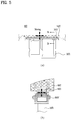
- FIG. 7 is a diagram to describe the variation of the card tray 165 shape when the tolerance occurs between the card socket 183 and the opening 106 .
- the support part 1651 may be arranged in response to the card socket 183 and the cover part 1652 may be arranged in response to the opening.
- the deformation of the flexible part 1653 may compensate the dislocation of 0.2 mm.
- the deformation of the flexible part 1653 may compensate the dislocation as well as the right and left dislocation.
- the mobile terminal may reduce an error rate by varying the positions of the cover part 1652 and the support part 1651 of the card tray 165 . Accordingly, even if the position of the card socket 183 becomes loose and dislocated, the card is able to be loaded in the mobile terminal 100 and then an initial error rate and an error rate caused during the usage of the mobile terminal may be reduced.
Landscapes
- Engineering & Computer Science (AREA)
- Signal Processing (AREA)
- Computer Networks & Wireless Communication (AREA)
- Artificial Intelligence (AREA)
- Computer Vision & Pattern Recognition (AREA)
- Physics & Mathematics (AREA)
- General Physics & Mathematics (AREA)
- Theoretical Computer Science (AREA)
- Telephone Set Structure (AREA)
Abstract
Description
Claims (5)
Applications Claiming Priority (1)
| Application Number | Priority Date | Filing Date | Title |
|---|---|---|---|
| PCT/KR2016/015462 WO2018124338A1 (en) | 2016-12-29 | 2016-12-29 | Mobile terminal |
Publications (2)
| Publication Number | Publication Date |
|---|---|
| US20190341953A1 US20190341953A1 (en) | 2019-11-07 |
| US10686480B2 true US10686480B2 (en) | 2020-06-16 |
Family
ID=62709558
Family Applications (1)
| Application Number | Title | Priority Date | Filing Date |
|---|---|---|---|
| US16/473,959 Active US10686480B2 (en) | 2016-12-29 | 2016-12-29 | Mobile terminal |
Country Status (3)
| Country | Link |
|---|---|
| US (1) | US10686480B2 (en) |
| KR (1) | KR102179824B1 (en) |
| WO (1) | WO2018124338A1 (en) |
Families Citing this family (1)
| Publication number | Priority date | Publication date | Assignee | Title |
|---|---|---|---|---|
| EP4391397A4 (en) | 2021-10-26 | 2024-12-25 | Samsung Electronics Co., Ltd. | SHELL SUPPORT STRUCTURE AND ELECTRONIC DEVICE THEREOF |
Citations (9)
| Publication number | Priority date | Publication date | Assignee | Title |
|---|---|---|---|---|
| US20080099559A1 (en) * | 2006-10-31 | 2008-05-01 | Macronix International Co., Ltd. | Dual Interface SIM Card Adapter with Detachable Antenna |
| US20080182622A1 (en) * | 2007-01-25 | 2008-07-31 | Sierra Wireless, Inc. | Method and Apparatus for Implementing a SIM Card Onboard a PC Card |
| KR20130142085A (en) | 2012-06-18 | 2013-12-27 | 타이코 일렉트로닉스 저팬 지.케이. | Card connector |
| JP2014182920A (en) | 2013-03-19 | 2014-09-29 | Yamaichi Electronics Co Ltd | Tray type card connector |
| JP2015027009A (en) | 2013-07-29 | 2015-02-05 | シャープ株式会社 | Mobile device |
| JP2015106554A (en) | 2013-12-03 | 2015-06-08 | Smk株式会社 | Tray type card connector |
| JP2016081808A (en) | 2014-10-20 | 2016-05-16 | モレックス エルエルシー | Card holding member and card connector set |
| US20160234362A1 (en) * | 2015-02-06 | 2016-08-11 | Samsung Electronics Co., Ltd. | Electronic device including display with bent area |
| US20170170584A1 (en) * | 2015-12-14 | 2017-06-15 | Le Holdings (Beijing) Co., Ltd. | Sim card slot and sim card tray and electronic product |
-
2016
- 2016-12-29 US US16/473,959 patent/US10686480B2/en active Active
- 2016-12-29 KR KR1020197017117A patent/KR102179824B1/en active Active
- 2016-12-29 WO PCT/KR2016/015462 patent/WO2018124338A1/en not_active Ceased
Patent Citations (9)
| Publication number | Priority date | Publication date | Assignee | Title |
|---|---|---|---|---|
| US20080099559A1 (en) * | 2006-10-31 | 2008-05-01 | Macronix International Co., Ltd. | Dual Interface SIM Card Adapter with Detachable Antenna |
| US20080182622A1 (en) * | 2007-01-25 | 2008-07-31 | Sierra Wireless, Inc. | Method and Apparatus for Implementing a SIM Card Onboard a PC Card |
| KR20130142085A (en) | 2012-06-18 | 2013-12-27 | 타이코 일렉트로닉스 저팬 지.케이. | Card connector |
| JP2014182920A (en) | 2013-03-19 | 2014-09-29 | Yamaichi Electronics Co Ltd | Tray type card connector |
| JP2015027009A (en) | 2013-07-29 | 2015-02-05 | シャープ株式会社 | Mobile device |
| JP2015106554A (en) | 2013-12-03 | 2015-06-08 | Smk株式会社 | Tray type card connector |
| JP2016081808A (en) | 2014-10-20 | 2016-05-16 | モレックス エルエルシー | Card holding member and card connector set |
| US20160234362A1 (en) * | 2015-02-06 | 2016-08-11 | Samsung Electronics Co., Ltd. | Electronic device including display with bent area |
| US20170170584A1 (en) * | 2015-12-14 | 2017-06-15 | Le Holdings (Beijing) Co., Ltd. | Sim card slot and sim card tray and electronic product |
Also Published As
| Publication number | Publication date |
|---|---|
| KR20190082908A (en) | 2019-07-10 |
| WO2018124338A1 (en) | 2018-07-05 |
| US20190341953A1 (en) | 2019-11-07 |
| KR102179824B1 (en) | 2020-11-17 |
Similar Documents
| Publication | Publication Date | Title |
|---|---|---|
| US10305165B2 (en) | Mobile terminal | |
| US10446913B2 (en) | Mobile terminal | |
| US9559740B2 (en) | Mobile terminal case and mobile terminal | |
| US9609099B2 (en) | Mobile terminal | |
| US10033844B2 (en) | Proximity illuminance sensor module and mobile terminal using same | |
| US9729688B2 (en) | Mobile terminal | |
| US10468816B2 (en) | Connector waterproof housing and mobile terminal | |
| US10613589B2 (en) | Electronic device | |
| CN106506733B (en) | Mobile terminal | |
| US20220077193A1 (en) | Display module and mobile terminal | |
| US10666779B2 (en) | Mobile terminal with coupling portion and molding unit for fixing and heat radiation structure | |
| US20180288201A1 (en) | Mobile terminal | |
| US10659577B2 (en) | Hinge for a foldable-type mobile device | |
| US9813098B2 (en) | Mobile terminal | |
| US9894191B2 (en) | Mobile terminal | |
| US10228577B2 (en) | Mobile terminal | |
| US9525763B1 (en) | Mobile terminal and assembling method thereof | |
| US9552016B2 (en) | Mobile terminal | |
| US10686480B2 (en) | Mobile terminal | |
| US20200091586A1 (en) | Mobile terminal | |
| US12009367B2 (en) | Mobile terminal | |
| KR20160015747A (en) | Mobile terminal and manufacturing method thereof | |
| KR20170017361A (en) | Mobile terminal |
Legal Events
| Date | Code | Title | Description |
|---|---|---|---|
| FEPP | Fee payment procedure |
Free format text: ENTITY STATUS SET TO UNDISCOUNTED (ORIGINAL EVENT CODE: BIG.); ENTITY STATUS OF PATENT OWNER: LARGE ENTITY |
|
| AS | Assignment |
Owner name: LG ELECTRONICS INC., KOREA, REPUBLIC OF Free format text: ASSIGNMENT OF ASSIGNORS INTEREST;ASSIGNOR:CHA, YOUNGDO;REEL/FRAME:049613/0906 Effective date: 20190621 |
|
| STPP | Information on status: patent application and granting procedure in general |
Free format text: RESPONSE TO NON-FINAL OFFICE ACTION ENTERED AND FORWARDED TO EXAMINER |
|
| STPP | Information on status: patent application and granting procedure in general |
Free format text: NOTICE OF ALLOWANCE MAILED -- APPLICATION RECEIVED IN OFFICE OF PUBLICATIONS |
|
| STPP | Information on status: patent application and granting procedure in general |
Free format text: PUBLICATIONS -- ISSUE FEE PAYMENT VERIFIED |
|
| STCF | Information on status: patent grant |
Free format text: PATENTED CASE |
|
| MAFP | Maintenance fee payment |
Free format text: PAYMENT OF MAINTENANCE FEE, 4TH YEAR, LARGE ENTITY (ORIGINAL EVENT CODE: M1551); ENTITY STATUS OF PATENT OWNER: LARGE ENTITY Year of fee payment: 4 |