US10683095B2 - Collapsible aspirator barrel - Google Patents
Collapsible aspirator barrel Download PDFInfo
- Publication number
- US10683095B2 US10683095B2 US15/368,172 US201615368172A US10683095B2 US 10683095 B2 US10683095 B2 US 10683095B2 US 201615368172 A US201615368172 A US 201615368172A US 10683095 B2 US10683095 B2 US 10683095B2
- Authority
- US
- United States
- Prior art keywords
- aspirator
- flotation device
- barrel
- inflatable flotation
- gas
- Prior art date
- Legal status (The legal status is an assumption and is not a legal conclusion. Google has not performed a legal analysis and makes no representation as to the accuracy of the status listed.)
- Active, expires
Links
- 238000005188 flotation Methods 0.000 claims abstract description 87
- 230000004044 response Effects 0.000 claims abstract description 69
- 239000012530 fluid Substances 0.000 claims abstract description 59
- 239000004744 fabric Substances 0.000 claims abstract description 17
- 239000000463 material Substances 0.000 claims description 16
- 239000000853 adhesive Substances 0.000 claims description 9
- 230000001070 adhesive effect Effects 0.000 claims description 9
- 229910000831 Steel Inorganic materials 0.000 claims description 7
- XAGFODPZIPBFFR-UHFFFAOYSA-N aluminium Chemical compound [Al] XAGFODPZIPBFFR-UHFFFAOYSA-N 0.000 claims description 7
- 229910052782 aluminium Inorganic materials 0.000 claims description 7
- 239000011521 glass Substances 0.000 claims description 7
- 239000010959 steel Substances 0.000 claims description 7
- 239000011248 coating agent Substances 0.000 claims description 6
- 238000000576 coating method Methods 0.000 claims description 6
- 229910000838 Al alloy Inorganic materials 0.000 claims description 5
- JOYRKODLDBILNP-UHFFFAOYSA-N Ethyl urethane Chemical compound CCOC(N)=O JOYRKODLDBILNP-UHFFFAOYSA-N 0.000 claims description 5
- 229920006231 aramid fiber Polymers 0.000 claims description 5
- 229920003235 aromatic polyamide Polymers 0.000 claims description 5
- 239000000835 fiber Substances 0.000 claims description 5
- 229920001084 poly(chloroprene) Polymers 0.000 claims description 5
- 238000000034 method Methods 0.000 description 10
- 230000008901 benefit Effects 0.000 description 6
- 239000002131 composite material Substances 0.000 description 5
- 229920001343 polytetrafluoroethylene Polymers 0.000 description 4
- 239000004810 polytetrafluoroethylene Substances 0.000 description 4
- 230000008569 process Effects 0.000 description 4
- 238000012856 packing Methods 0.000 description 3
- 229920000049 Carbon (fiber) Polymers 0.000 description 2
- 239000004917 carbon fiber Substances 0.000 description 2
- 229920001971 elastomer Polymers 0.000 description 2
- 230000007613 environmental effect Effects 0.000 description 2
- VNWKTOKETHGBQD-UHFFFAOYSA-N methane Chemical compound C VNWKTOKETHGBQD-UHFFFAOYSA-N 0.000 description 2
- 239000002114 nanocomposite Substances 0.000 description 2
- 239000004033 plastic Substances 0.000 description 2
- 229920003023 plastic Polymers 0.000 description 2
- 239000004809 Teflon Substances 0.000 description 1
- 229920006362 Teflon® Polymers 0.000 description 1
- 230000009471 action Effects 0.000 description 1
- 230000009172 bursting Effects 0.000 description 1
- 230000008878 coupling Effects 0.000 description 1
- 238000010168 coupling process Methods 0.000 description 1
- 238000005859 coupling reaction Methods 0.000 description 1
- 230000000694 effects Effects 0.000 description 1
- 238000004806 packaging method and process Methods 0.000 description 1
- -1 polytetrafluoroethylene Polymers 0.000 description 1
- 230000009467 reduction Effects 0.000 description 1
- 230000000717 retained effect Effects 0.000 description 1
- 239000000126 substance Substances 0.000 description 1
- BFKJFAAPBSQJPD-UHFFFAOYSA-N tetrafluoroethene Chemical compound FC(F)=C(F)F BFKJFAAPBSQJPD-UHFFFAOYSA-N 0.000 description 1
Images


Classifications
-
- B—PERFORMING OPERATIONS; TRANSPORTING
- B64—AIRCRAFT; AVIATION; COSMONAUTICS
- B64D—EQUIPMENT FOR FITTING IN OR TO AIRCRAFT; FLIGHT SUITS; PARACHUTES; ARRANGEMENT OR MOUNTING OF POWER PLANTS OR PROPULSION TRANSMISSIONS IN AIRCRAFT
- B64D25/00—Emergency apparatus or devices, not otherwise provided for
- B64D25/08—Ejecting or escaping means
- B64D25/14—Inflatable escape chutes
-
- F—MECHANICAL ENGINEERING; LIGHTING; HEATING; WEAPONS; BLASTING
- F04—POSITIVE - DISPLACEMENT MACHINES FOR LIQUIDS; PUMPS FOR LIQUIDS OR ELASTIC FLUIDS
- F04F—PUMPING OF FLUID BY DIRECT CONTACT OF ANOTHER FLUID OR BY USING INERTIA OF FLUID TO BE PUMPED; SIPHONS
- F04F5/00—Jet pumps, i.e. devices in which flow is induced by pressure drop caused by velocity of another fluid flow
- F04F5/14—Jet pumps, i.e. devices in which flow is induced by pressure drop caused by velocity of another fluid flow the inducing fluid being elastic fluid
- F04F5/16—Jet pumps, i.e. devices in which flow is induced by pressure drop caused by velocity of another fluid flow the inducing fluid being elastic fluid displacing elastic fluids
- F04F5/20—Jet pumps, i.e. devices in which flow is induced by pressure drop caused by velocity of another fluid flow the inducing fluid being elastic fluid displacing elastic fluids for evacuating
-
- B—PERFORMING OPERATIONS; TRANSPORTING
- B64—AIRCRAFT; AVIATION; COSMONAUTICS
- B64D—EQUIPMENT FOR FITTING IN OR TO AIRCRAFT; FLIGHT SUITS; PARACHUTES; ARRANGEMENT OR MOUNTING OF POWER PLANTS OR PROPULSION TRANSMISSIONS IN AIRCRAFT
- B64D25/00—Emergency apparatus or devices, not otherwise provided for
- B64D25/08—Ejecting or escaping means
- B64D25/18—Flotation gear
-
- F—MECHANICAL ENGINEERING; LIGHTING; HEATING; WEAPONS; BLASTING
- F04—POSITIVE - DISPLACEMENT MACHINES FOR LIQUIDS; PUMPS FOR LIQUIDS OR ELASTIC FLUIDS
- F04B—POSITIVE-DISPLACEMENT MACHINES FOR LIQUIDS; PUMPS
- F04B37/00—Pumps having pertinent characteristics not provided for in, or of interest apart from, groups F04B25/00 - F04B35/00
- F04B37/10—Pumps having pertinent characteristics not provided for in, or of interest apart from, groups F04B25/00 - F04B35/00 for special use
-
- F—MECHANICAL ENGINEERING; LIGHTING; HEATING; WEAPONS; BLASTING
- F04—POSITIVE - DISPLACEMENT MACHINES FOR LIQUIDS; PUMPS FOR LIQUIDS OR ELASTIC FLUIDS
- F04B—POSITIVE-DISPLACEMENT MACHINES FOR LIQUIDS; PUMPS
- F04B39/00—Component parts, details, or accessories, of pumps or pumping systems specially adapted for elastic fluids, not otherwise provided for in, or of interest apart from, groups F04B25/00 - F04B37/00
- F04B39/10—Adaptations or arrangements of distribution members
-
- F—MECHANICAL ENGINEERING; LIGHTING; HEATING; WEAPONS; BLASTING
- F04—POSITIVE - DISPLACEMENT MACHINES FOR LIQUIDS; PUMPS FOR LIQUIDS OR ELASTIC FLUIDS
- F04F—PUMPING OF FLUID BY DIRECT CONTACT OF ANOTHER FLUID OR BY USING INERTIA OF FLUID TO BE PUMPED; SIPHONS
- F04F5/00—Jet pumps, i.e. devices in which flow is induced by pressure drop caused by velocity of another fluid flow
- F04F5/44—Component parts, details, or accessories not provided for in, or of interest apart from, groups F04F5/02 - F04F5/42
- F04F5/46—Arrangements of nozzles
- F04F5/461—Adjustable nozzles
-
- F—MECHANICAL ENGINEERING; LIGHTING; HEATING; WEAPONS; BLASTING
- F04—POSITIVE - DISPLACEMENT MACHINES FOR LIQUIDS; PUMPS FOR LIQUIDS OR ELASTIC FLUIDS
- F04F—PUMPING OF FLUID BY DIRECT CONTACT OF ANOTHER FLUID OR BY USING INERTIA OF FLUID TO BE PUMPED; SIPHONS
- F04F5/00—Jet pumps, i.e. devices in which flow is induced by pressure drop caused by velocity of another fluid flow
- F04F5/44—Component parts, details, or accessories not provided for in, or of interest apart from, groups F04F5/02 - F04F5/42
- F04F5/46—Arrangements of nozzles
- F04F5/466—Arrangements of nozzles with a plurality of nozzles arranged in parallel
Definitions
- the present disclosure is directed to evacuation systems for use in aircraft and, more particularly, to aspirators designed to provide air for inflating evacuation devices.
- Inflatable evacuation devices such as aircraft evacuation slides and emergency life rafts, typically include a compressed fluid source (such as a charged gas cylinder) and an aspirator.
- a compressed fluid source such as a charged gas cylinder
- the aspirator working with the charged gas cylinder, combines gas from the atmosphere and the fluid to provide gas for inflating the emergency evacuation devices.
- Aspirators are typically stored in a limited packing space and, thus, the evacuation device package is often densely packaged. The process of packing the emergency evacuation devices may be relatively difficult due to the limited packing space.
- the aspirator for inflating an inflatable flotation device.
- the aspirator includes an aspirator body having at least one flapper door designed to allow intake of a gas from an environment of the aspirator.
- the aspirator also includes an aspirator barrel coupled to the aspirator body and the inflatable flotation device, having an end tip, a compressible spring, and a fabric positioned about the compressible spring, and designed to extend in response to receiving the gas and to transfer the gas from the aspirator body to the inflatable flotation device.
- the aspirator also includes a gas valve coupled to the aspirator body and designed to receive a fluid from a compressed fluid source.
- the aspirator also includes a nozzle positioned within the aspirator body, coupled to the gas valve, and designed to receive the fluid via the gas valve and to direct at least a portion of the fluid towards the aspirator barrel such that the at least one flapper door allows the gas to flow from the environment into the aspirator barrel.
- the end tip of the aspirator barrel has a glass coating to reduce friction between the end tip and the inflatable flotation device during extension of the aspirator barrel.
- any of the foregoing embodiments may include a cap designed to be disposed on the end tip of the aspirator barrel, to prevent at least one of the gas or the fluid from flowing into the inflatable flotation device during at least a portion of extension of the aspirator barrel within the inflatable flotation device, and to allow at least one of the gas or the fluid to flow into the inflatable flotation device response to pressure within the aspirator barrel reaching a predetermined pressure.
- the cap includes a burst disk designed to rupture in response to the pressure within the aspirator barrel reaching the predetermined pressure.
- the cap includes a snap-fit feature designed to release from the end tip in response to the pressure within the aspirator barrel reaching the predetermined pressure.
- any of the foregoing embodiments may also include an adhesive attaching the cap to the end tip and designed to allow the cap to detach from the end tip in response to the pressure within the aspirator barrel reaching the predetermined pressure.
- the predetermined pressure is selected such that the aspirator barrel is in a fully extended position in response to the pressure within the aspirator barrel being the predetermined pressure.
- the aspirator is configured to be used with an evacuation system of an aircraft.
- the compressible spring of the aspirator barrel includes at least one of aluminum, an aluminum alloy, or steel and the fabric of the aspirator barrel includes at least one of a neoprene, a urethane, an aramid fiber, or a para-aramid fiber.
- the evacuation system includes an inflatable flotation device designed to float in response to being inflated.
- the evacuation system also includes a compressed fluid source designed to store a fluid in a compressed state.
- the evacuation system also includes an aspirator.
- the aspirator includes an aspirator body having at least one flapper door designed to allow intake of a gas from an environment of the aspirator.
- the aspirator also includes an aspirator barrel coupled to the aspirator body and the inflatable flotation device, having an end tip, a compressible spring, and a fabric positioned about the compressible spring, and designed to extend in response to receiving the gas and to transfer the gas from the aspirator body to the inflatable flotation device.
- the aspirator also includes a gas valve coupled to the aspirator body and designed to receive the fluid from the compressed fluid source.
- the aspirator also includes a nozzle positioned within the aspirator body, coupled to the gas valve, and designed to receive the fluid via the gas valve and to direct at least a portion of the fluid towards the aspirator barrel such that the at least one flapper door allows the gas to flow from the environment into the aspirator barrel.
- the end tip of the aspirator barrel has a glass coating to reduce friction between the end tip and the inflatable flotation device during extension of the aspirator barrel.
- the aspirator further includes a cap designed to be disposed on the end tip of the aspirator barrel, to prevent at least one of the gas or the fluid from flowing into the inflatable flotation device during at least a portion of extension of the aspirator barrel within the inflatable flotation device, and to allow at least one of the gas or the fluid to flow into the inflatable flotation device response to pressure within the aspirator barrel reaching a predetermined pressure.
- the cap includes at least one of a burst disk designed to rupture in response to the pressure within the aspirator barrel reaching the predetermined pressure, or a snap-fit feature designed to release from the end tip in response to the pressure within the aspirator barrel reaching the predetermined pressure.
- the aspirator further includes an adhesive attaching the cap to the end tip and designed to allow the cap to detach from the end tip in response to the pressure within the aspirator barrel reaching the predetermined pressure.
- the predetermined pressure is selected such that the aspirator barrel is in a fully extended position in response to the pressure within the aspirator barrel being the predetermined pressure.
- the compressible spring of the aspirator barrel includes at least one of aluminum, an aluminum alloy, or steel and the fabric of the aspirator barrel includes at least one of a neoprene, a urethane, an aramid fiber, or a para-aramid fiber.
- the aircraft having an evacuation system.
- the aircraft includes a fuselage, an inflatable flotation device removably coupled to the fuselage and designed to float in response to being inflated, and a compressed fluid source coupled to the inflatable flotation device and designed to store a fluid in a compressed state.
- the aircraft also includes an aspirator coupled to the inflatable flotation device.
- the aspirator includes an aspirator body having at least one flapper door designed to allow intake of a gas from an environment of the aspirator.
- the aspirator also includes an aspirator barrel coupled to the aspirator body and the inflatable flotation device, having an end tip, a compressible spring, and a fabric positioned about the compressible spring, and designed to extend in response to receiving the gas and to transfer the gas from the aspirator body to the inflatable flotation device.
- the aspirator also includes a gas valve coupled to the aspirator body and designed to receive the fluid from the compressed fluid source.
- the aspirator also includes a nozzle positioned within the aspirator body, coupled to the gas valve, and designed to receive the fluid via the gas valve and to direct at least a portion of the fluid towards the aspirator barrel such that the at least one flapper door allows the gas to flow from the environment into the aspirator barrel.
- the end tip of the aspirator barrel has a glass coating to reduce friction between the end tip and the inflatable flotation device during extension of the aspirator barrel.
- the aspirator further includes a cap designed to be disposed on the end tip of the aspirator barrel, to prevent at least one of the gas or the fluid from flowing into the inflatable flotation device during at least a portion of extension of the aspirator barrel within the inflatable flotation device, and to allow at least one of the gas or the fluid to flow into the inflatable flotation device response to pressure within the aspirator barrel reaching a predetermined pressure.
- the cap includes at least one of a burst disk designed to rupture in response to the pressure within the aspirator barrel reaching the predetermined pressure, or a snap-fit feature designed to release from the end tip in response to the pressure within the aspirator barrel reaching the predetermined pressure.
- FIG. 1 is a drawing of an aircraft having an exit door and an evacuation system, in accordance with various embodiments
- FIG. 2 is a drawing of the evacuation system of FIG. 1 including an aspirator, in accordance with various embodiments;
- FIG. 3 is a drawing of the aspirator of FIG. 2 illustrating features of the aspirator, in accordance with various embodiments;
- FIG. 4 is a drawing of the aspirator of FIG. 2 in a compressed state, in accordance with various embodiments;
- FIG. 5 is a drawing of the aspirator of FIG. 2 in a fully extended state, in accordance with various embodiments;
- FIG. 6 is a drawing of an aspirator in a compressed state, in accordance with various embodiments.
- FIG. 7 is a drawing of the aspirator of FIG. 6 in a fully extended state, in accordance with various embodiments;
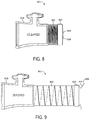
- FIG. 8 is a drawing of an aspirator in a compressed state, in accordance with various embodiments.
- FIG. 9 is a drawing of the aspirator of FIG. 8 in a fully extended state, in accordance with various embodiments.
- the aircraft 100 may include a fuselage 101 having plurality of exit doors including an exit door 102 .
- the aircraft 100 may include one or more evacuation systems positioned near a corresponding exit door.
- the aircraft 100 includes an evacuation system 104 positioned near the exit door 102 .
- the evacuation system 104 may be removably coupled to the fuselage 101 .
- the exit door 102 may be opened by a passenger or crew member of the aircraft 100 .
- the evacuation system 104 may deploy in response to the exit door 102 being opened and, in various embodiments, the evacuation system 104 may deploy in response to another action taken by a passenger or crew member such as depression of a button or actuation of a lever.
- the evacuation system 104 includes an inflatable flotation device 200 .
- the evacuation system 104 further includes a source of forced gas 206 .
- the source of forced gas 206 may cause a gas to enter the inflatable flotation device 200 to inflate the inflatable flotation device 200 .
- the inflatable flotation device 200 may be coupled to the fuselage 101 of FIG. 1 , and may be decoupled from the fuselage 101 in response to being fully inflated or manually detached to allow passengers and/or crew members to safely float away from the aircraft 100 of FIG. 1 .
- the source of forced gas 206 may include an aspirator 202 coupled to the inflatable flotation device 200 , piping 204 coupled to the aspirator 202 , and a compressed fluid source 208 coupled to the piping 204 .
- the inflatable flotation device 200 may be deflated and stored within a compartment of the aircraft 100 .
- the inflatable flotation device 200 and the aspirator 202 may be stored in a single package within the aircraft compartment.
- fluid may flow into the aspirator 202 via the piping 204 at a relatively high velocity. This fluid flow may cause the aspirator 202 to draw gas from the environment.
- the fluid flow (such as in a gaseous state) and the environmental gas may be directed into the inflatable flotation device 200 .
- the inflatable flotation device 200 may begin to inflate.
- the aspirator 202 includes an aspirator body 318 , whose cross section is shown, connected to an aspirator barrel 302 .
- the aspirator body 318 may be formed from a rigid material such as aluminum, steel, carbon fiber composite material, a nano-composite material, or another rigid composite material such as polytetrafluoroethylene (PTFE) (available under the trademark TEFLON).
- a rigid material such as aluminum, steel, carbon fiber composite material, a nano-composite material, or another rigid composite material such as polytetrafluoroethylene (PTFE) (available under the trademark TEFLON).
- PTFE polytetrafluoroethylene
- the aspirator barrel 302 is capable of being in a compressed state (as shown in FIG. 4 ) and also capable of being in a fully extended position or state (as shown in FIG. 5 ).
- the aspirator barrel 302 may comprise a compressible spring 400 and a fabric 402 that is relatively flexible.
- the aspirator barrel 302 may also include an end tip 334 that is designed to extend farther in the inflatable flotation device 200 than the remainder of the aspirator barrel 302 .
- the fabric 402 may include the same material as is used in the inflatable flotation device 200 .
- the flexible fabric has a relatively high tensile strength and is made of, for example, a neoprene, a urethane, an aramid fiber, and/or a para-aramid fiber.
- the compressible spring 400 may be relatively flexible and have a relatively high yield strength.
- the compressible spring 400 may include at least one of aluminum, an aluminum alloy, or steel.
- the end tip 334 may be formed from a rigid material such as aluminum, steel, carbon fiber composite material, a nano-composite material, or another rigid composite material such as PTFE. In various embodiments, the end tip 334 may be formed from the same material as the aspirator body 318 . In various embodiments, it is desirable for the end tip 334 to have a relatively low coefficient of friction in order to reduce friction between the end tip 334 and an inner surface of the inflatable flotation device 200 . A reduction in friction between these two components reduces the likelihood of damage to the inflatable flotation device 200 during extension of the aspirator barrel 302 and during inflation of the inflatable flotation device 200 . In that regard, the end tip 334 may be coated with a material having a relatively low coefficient of friction such as a glass or PTFE.
- the aspirator barrel 302 may be compacted prior to being packaged with the inflatable flotation device 200 . This advantageously results in the aspirator 202 filling less space within the packaging.
- the aspirator body 318 may also include a nozzle 304 (such as a showerhead nozzle or manifold), at least one flapper door (such as a first flapper door 306 A and a second flapper door 306 B), and a gas valve 308 .
- the nozzle 304 may be coupled to the gas valve 308 .
- the gas valve 308 may direct a fluid from the compressed fluid source 208 , such as a charged cylinder, through the nozzle 304 and into an aspirator chamber 310 .
- the aspirator chamber 310 is defined by the aspirator body 318 .
- the aspirator body 318 may include the rigid material in order to protect the gas valve 308 , the nozzle 304 , and the flapper doors 306 A, 306 B, as well as ensuring the aspirator chamber 310 is defined.
- gas from the environment of the aspirator 202 is compelled into the aspirator chamber 310 from outside the aspirator 202 (as shown by an arrow 342 ) due to the Venturi effect.
- the aspirator 202 facilitates intake of gas from the environment. The gas enters the aspirator chamber 310 through the flapper doors 306 A, 306 B.
- the flapper doors 306 A, 306 B are designed to open inward to allow compelled gas to enter the aspirator chamber 310 .
- the flapper doors 306 A, 306 B are also designed to keep the atmospheric gas from exiting the aspirator chamber 310 via the flapper doors 306 A, 306 B by functioning as a one-way valve. As shown in FIG. 3 , the flapper doors 306 A, 306 B are in a closed configuration, as high-pressure gas is not being provided to the aspirator chamber 310 via the gas valve 308 and the nozzle 304 .
- the aspirator barrel 302 may include a first end 320 coupled to the aspirator body 318 and a second end 322 (on which the end tip 334 is positioned) that extends into the inflatable flotation device 200 .
- the aspirator barrel 302 may be connected to the aspirator body 318 by wrapping a band clamp 344 around a flange connection between the aspirator body 318 and the aspirator barrel 302 .
- the aspirator 202 is shown with the aspirator barrel 302 in the compressed state.
- the aspirator 202 may be packaged with the inflatable flotation device 200 while in the compressed state.
- At least a portion of the aspirator barrel 302 is positioned within the inflatable flotation device 200 .
- at least a portion of the aspirator barrel 302 extends within the inflatable flotation device 200 . It is desirable for at least a portion of the aspirator barrel 302 to extend within the inflatable flotation device 200 to increase the likelihood of a relatively constant inflation rate of the inflatable flotation device 200 . Thus, it is also desirable for the aspirator barrel 302 to become at least partially extended prior to inflation of the inflatable flotation device 200 .
- the end tip 334 may include a cap 404 to facilitate extension of the aspirator barrel 302 within the inflatable flotation device 200 .
- the cap 404 may include any flexible or inflexible material that nearly prevents or substantially reduces a flow of gas therethrough.
- the cap may include a plastic, a rubber, or a composite material.
- the inflatable flotation device 200 may be folded prior to storage.
- the inflatable flotation device 200 may unfold in response to deployment of the evacuation system 104 .
- the compressible spring 400 may begin to extend, at least partially elongating the aspirator barrel 302 within the inflatable flotation device 200 .
- the force of the compressible spring 400 may not be sufficient to force the aspirator barrel 302 into the fully extended position.
- the cap 404 may cover an aperture of the end tip 334 and may be bonded to the end tip 334 via an adhesive 406 .
- the adhesive 406 causes the cap 404 to remain on the end tip 334 .
- the cap 404 prevents the gas from flowing into the inflatable flotation device 200 .
- pressure builds within the aspirator barrel 302 , causing the aspirator barrel 302 to extend.
- the adhesive 406 may be designed to cause the cap 404 to remain coupled to the end tip 334 until pressure within the aspirator barrel 302 reaches a predetermined pressure. Stated differently, adhesive 406 may release the cap 404 from the end tip 334 in response to pressure within the aspirator barrel 302 reaching the predetermined pressure.
- the predetermined pressure may correspond to a pressure at which the aspirator barrel 302 is in a partially or fully extended state. Stated differently, the pressure within the aspirator barrel 302 may reach the predetermined pressure in response to the aspirator barrel 302 reaching the fully extended state. Thus, the cap 404 may become removed from the end tip 334 in response to the aspirator barrel 302 reaching the fully extended state, as shown in FIG. 5 . Accordingly, in response to the aspirator barrel 302 reaching the fully extended state and the cap detaching from the end tip 334 , gas may flow through the aspirator barrel 302 into the inflatable flotation device 200 .
- the predetermined pressure may be between 10 pounds per square inch (PSI, 68.9 Kilopascal (kPa) and 350 PSI (276 kPa), between 15 PSI (103 kPa) and 300 PSI (207 kPa), or between 20 PSI (138 kPa) and 200 PSI (276 kPa). In various embodiments, the predetermined pressure may be relatively high in order to withstand an initial impact pressure of fluid output by the aspirator body 318 .
- another aspirator 601 may have a compressed state (as shown in FIG. 6 ) and a fully extended state (as shown in FIG. 7 ).
- the aspirator 601 may have similar features as the aspirator 202 of FIG. 4 .
- the aspirator 601 includes an aspirator barrel 602 having an end tip 634 and an aspirator body 618 .
- the aspirator barrel 602 may include a compressible spring and fabric, similar to the aspirator barrel 302 of FIG. 3 .
- the aspirator 601 may include a cap 604 that attaches to the end tip 634 via a snap-fit feature 606 .
- the end tip 634 may include a flange 608 that extends outward from the end tip 634 .
- the snap-fit feature 606 may include a lip.
- the snap-fit feature 606 (such as the lip) may be positioned about the flange 608 .
- the cap may be retained in place relative to the end tip 634 in response to the snap-fit feature 606 being positioned about the flange.
- the gas may build pressure within the aspirator barrel 602 causing the aspirator barrel 602 to extend.
- Any other snap fit feature may be included with at least one of the end tip 634 or the cap 604 .
- the snap-fit feature 606 may be designed to release from the flange 608 in response to pressure within the aspirator barrel 602 reaching a predetermined pressure.
- the predetermined pressure may correspond to a pressure at which the aspirator barrel 602 is in a partially or fully extended state.
- the cap 604 may separate from the end tip 634 in response to the pressure within the aspirator barrel 602 reaching the predetermined pressure. Accordingly, air may flow through the aspirator barrel 602 via the aspirator body 618 in response to the aspirator barrel 602 becoming fully extended.
- another aspirator 801 may have a compressed state (as shown in FIG. 8 ) and a fully extended state (as shown in FIG. 9 ).
- the aspirator 801 may have similar features as the aspirator 202 of FIG. 4 .
- the aspirator 801 includes an aspirator barrel 802 having an end tip 834 and an aspirator body 818 .
- the aspirator barrel 802 may include a compressible spring and fabric, similar to the aspirator barrel 302 of FIG. 3 .
- the aspirator 801 may include a cap 604 that functions as a burst disk 806 .
- the burst disk 806 may be coupled to the end tip 834 via an adhesive or other attachment means. Unlike the cap 404 of FIG. 4 and the cap 604 of FIG. 6 , the burst disk 806 may not release from the end tip 834 in response to pressure within the aspirator barrel 802 reaching a predetermined pressure.
- the burst disk 806 may be designed to rupture in response to pressure within the aspirator barrel 802 reaching the predetermined pressure.
- the predetermined pressure may correspond to a pressure at which the aspirator barrel 802 is in a partially or fully extended state.
- the burst disk 806 may rupture in response to the pressure within the aspirator barrel 802 reaching the predetermined pressure. Accordingly, air may flow through the aspirator barrel 802 via the aspirator body 818 in response to the aspirator barrel 802 becoming fully extended.
- the burst disk 806 may include any material capable of bursting in response to a predetermined amount of pressure.
- the burst disk 806 may include a plastic, a rubber, or another material.
- the burst disk 806 may be relatively thin. The thickness and the material of the burst disk 806 may be selected such that the burst disk 806 will rupture in response to the pressure within the aspirator barrel 802 reaching the predetermined pressure.
- the burst disk 806 may be scored in one or more location to facilitate rupturing in response to the pressure within the aspirator barrel 802 reaching the predetermined pressure.
- references to “one embodiment”, “an embodiment”, “an example embodiment”, etc. indicate that the embodiment described may include a particular feature, structure, or characteristic, but every embodiment may not necessarily include the particular feature, structure, or characteristic. Moreover, such phrases are not necessarily referring to the same embodiment. Further, when a particular feature, structure, or characteristic is described in connection with an embodiment, it is submitted that it is within the knowledge of one skilled in the art to affect such feature, structure, or characteristic in connection with other embodiments whether or not explicitly described. After reading the description, it will be apparent to one skilled in the relevant art(s) how to implement the disclosure in alternative embodiments.
Landscapes
- Engineering & Computer Science (AREA)
- Mechanical Engineering (AREA)
- General Engineering & Computer Science (AREA)
- Physics & Mathematics (AREA)
- Fluid Mechanics (AREA)
- Business, Economics & Management (AREA)
- Emergency Management (AREA)
- Aviation & Aerospace Engineering (AREA)
- Pressure Vessels And Lids Thereof (AREA)
- Filling Or Discharging Of Gas Storage Vessels (AREA)
- Jet Pumps And Other Pumps (AREA)
Abstract
Description
Claims (17)
Priority Applications (3)
| Application Number | Priority Date | Filing Date | Title |
|---|---|---|---|
| US15/368,172 US10683095B2 (en) | 2016-12-02 | 2016-12-02 | Collapsible aspirator barrel |
| CN201711248871.5A CN108146640B (en) | 2016-12-02 | 2017-12-01 | System for inflating a flotation device, aircraft with an evacuation system and evacuation system |
| EP17205269.8A EP3330547B1 (en) | 2016-12-02 | 2017-12-04 | Collapsible aspirator barrel |
Applications Claiming Priority (1)
| Application Number | Priority Date | Filing Date | Title |
|---|---|---|---|
| US15/368,172 US10683095B2 (en) | 2016-12-02 | 2016-12-02 | Collapsible aspirator barrel |
Publications (2)
| Publication Number | Publication Date |
|---|---|
| US20180155039A1 US20180155039A1 (en) | 2018-06-07 |
| US10683095B2 true US10683095B2 (en) | 2020-06-16 |
Family
ID=60582432
Family Applications (1)
| Application Number | Title | Priority Date | Filing Date |
|---|---|---|---|
| US15/368,172 Active 2037-11-02 US10683095B2 (en) | 2016-12-02 | 2016-12-02 | Collapsible aspirator barrel |
Country Status (3)
| Country | Link |
|---|---|
| US (1) | US10683095B2 (en) |
| EP (1) | EP3330547B1 (en) |
| CN (1) | CN108146640B (en) |
Families Citing this family (1)
| Publication number | Priority date | Publication date | Assignee | Title |
|---|---|---|---|---|
| US10718356B2 (en) * | 2018-02-12 | 2020-07-21 | Goodrich Corporation | Aspirator inflatable diffuser |
Citations (16)
| Publication number | Priority date | Publication date | Assignee | Title |
|---|---|---|---|---|
| US3460746A (en) * | 1967-10-27 | 1969-08-12 | Rocket Research Corp | Two-stage inflation aspirator |
| US3468472A (en) * | 1967-09-15 | 1969-09-23 | Global Systems | Flow augmented nozzle |
| US3598504A (en) * | 1969-10-29 | 1971-08-10 | Vincent F Siravo | Self-regulating aspirator |
| US3684404A (en) | 1971-03-16 | 1972-08-15 | Rocket Research Corp | Inflating apparatus |
| US3791764A (en) * | 1972-03-01 | 1974-02-12 | Garrett Corp | Variable area ratio jet pump |
| EP0046275A1 (en) | 1980-08-15 | 1982-02-24 | The B.F. GOODRICH Company | Aspirator for inflating flexible products |
| WO1983002981A1 (en) | 1982-02-23 | 1983-09-01 | Gen Pneumatics Corp | Fluid apparatus and methods, as for inflating inflatable structures |
| US4460343A (en) | 1982-03-29 | 1984-07-17 | The B. F. Goodrich Company | Inflatable container packing system |
| US4566862A (en) * | 1982-02-23 | 1986-01-28 | General Pneumatics Corporation | Fluid apparatus and methods, as for inflating inflatable structures |
| US5002465A (en) | 1989-10-12 | 1991-03-26 | The Boeing Company | Off-on control for an inflation aspirator |
| US6071084A (en) | 1995-11-14 | 2000-06-06 | Wass; Lloyd G. | Aspirator |
| US20100266424A1 (en) | 2009-04-16 | 2010-10-21 | Goodrich Corporation | Inflation aspirator with collapsible barrel |
| US20140072261A1 (en) * | 2012-09-10 | 2014-03-13 | Corning Cable Systems Llc | Docking stations, electronic devices, and fiber optic cable assemblies having a magnetic optical connection |
| US20160102682A1 (en) | 2014-10-10 | 2016-04-14 | Circor Aerospace, Inc. | Aspirator and method of fabricating |
| US20170016459A1 (en) * | 2015-07-17 | 2017-01-19 | Goodrich Corporation | Collapsible/ extendable aspirator system |
| US20170297726A1 (en) * | 2016-04-15 | 2017-10-19 | Goodrich Corporation | Collapsible inflatable aspirator system |
Family Cites Families (3)
| Publication number | Priority date | Publication date | Assignee | Title |
|---|---|---|---|---|
| US6644592B2 (en) * | 2001-09-21 | 2003-11-11 | Apical Industries, Inc. | Floatation system |
| US7032778B2 (en) * | 2003-01-30 | 2006-04-25 | Goodrich Corporation | Overpressure limiting hybrid inflator |
| FI126435B (en) * | 2014-10-17 | 2016-11-30 | Skycat Oy | A method and apparatus for firing an object from a flying device |
-
2016
- 2016-12-02 US US15/368,172 patent/US10683095B2/en active Active
-
2017
- 2017-12-01 CN CN201711248871.5A patent/CN108146640B/en active Active
- 2017-12-04 EP EP17205269.8A patent/EP3330547B1/en active Active
Patent Citations (20)
| Publication number | Priority date | Publication date | Assignee | Title |
|---|---|---|---|---|
| US3468472A (en) * | 1967-09-15 | 1969-09-23 | Global Systems | Flow augmented nozzle |
| US3460746A (en) * | 1967-10-27 | 1969-08-12 | Rocket Research Corp | Two-stage inflation aspirator |
| US3598504A (en) * | 1969-10-29 | 1971-08-10 | Vincent F Siravo | Self-regulating aspirator |
| US3684404A (en) | 1971-03-16 | 1972-08-15 | Rocket Research Corp | Inflating apparatus |
| US3791764A (en) * | 1972-03-01 | 1974-02-12 | Garrett Corp | Variable area ratio jet pump |
| EP0046275A1 (en) | 1980-08-15 | 1982-02-24 | The B.F. GOODRICH Company | Aspirator for inflating flexible products |
| US4368009A (en) * | 1980-08-15 | 1983-01-11 | The B. F. Goodrich Company | Aspirator |
| WO1983002981A1 (en) | 1982-02-23 | 1983-09-01 | Gen Pneumatics Corp | Fluid apparatus and methods, as for inflating inflatable structures |
| US4566862A (en) * | 1982-02-23 | 1986-01-28 | General Pneumatics Corporation | Fluid apparatus and methods, as for inflating inflatable structures |
| US4460343A (en) | 1982-03-29 | 1984-07-17 | The B. F. Goodrich Company | Inflatable container packing system |
| US5002465A (en) | 1989-10-12 | 1991-03-26 | The Boeing Company | Off-on control for an inflation aspirator |
| US6071084A (en) | 1995-11-14 | 2000-06-06 | Wass; Lloyd G. | Aspirator |
| US20100266424A1 (en) | 2009-04-16 | 2010-10-21 | Goodrich Corporation | Inflation aspirator with collapsible barrel |
| US8066493B2 (en) | 2009-04-16 | 2011-11-29 | Goodrich Corporation | Inflation aspirator with collapsible barrel |
| US20140072261A1 (en) * | 2012-09-10 | 2014-03-13 | Corning Cable Systems Llc | Docking stations, electronic devices, and fiber optic cable assemblies having a magnetic optical connection |
| US20160102682A1 (en) | 2014-10-10 | 2016-04-14 | Circor Aerospace, Inc. | Aspirator and method of fabricating |
| US20170016459A1 (en) * | 2015-07-17 | 2017-01-19 | Goodrich Corporation | Collapsible/ extendable aspirator system |
| US9863442B2 (en) * | 2015-07-17 | 2018-01-09 | Goodrich Corporation | Collapsible/extendable aspirator system |
| US20180087537A1 (en) * | 2015-07-17 | 2018-03-29 | Goodrich Corporation | Collapsible/ extendable aspirator system |
| US20170297726A1 (en) * | 2016-04-15 | 2017-10-19 | Goodrich Corporation | Collapsible inflatable aspirator system |
Non-Patent Citations (1)
| Title |
|---|
| European Patent Office, European Search Report dated Apr. 26, 2018 in application No. 17205269.8-1004. |
Also Published As
| Publication number | Publication date |
|---|---|
| US20180155039A1 (en) | 2018-06-07 |
| EP3330547A1 (en) | 2018-06-06 |
| CN108146640B (en) | 2022-07-08 |
| EP3330547B1 (en) | 2020-02-05 |
| CN108146640A (en) | 2018-06-12 |
Similar Documents
| Publication | Publication Date | Title |
|---|---|---|
| EP3118117B1 (en) | Collapsible/ extendable aspirator system | |
| US10780986B2 (en) | Collapsible inflatable aspirator system | |
| US10640186B2 (en) | Inflation device and method of use | |
| Viquerat et al. | Inflatable rigidisable mast for end-of-life deorbiting system | |
| US10710733B2 (en) | Evacuation slide with aspirator retention strap | |
| US11198514B2 (en) | Aspirator with pressure relief flaps | |
| CN106064675A (en) | Soft set releasing mechanism for evacuation slide | |
| US10683095B2 (en) | Collapsible aspirator barrel | |
| US11174878B2 (en) | Aspirator system | |
| US20200182364A1 (en) | Venting inflation valve aspirator | |
| US10384789B2 (en) | Aspirator assembly with integrated pressure relief valve | |
| US11299282B2 (en) | Regulator with orientation valve | |
| US10718356B2 (en) | Aspirator inflatable diffuser | |
| US11649931B2 (en) | Monolithic pressure regulator | |
| CN108082443B (en) | Redundant layer for inflatable evacuation components | |
| US10654574B2 (en) | Airfoil for steadying an evacuation slide | |
| US11591095B2 (en) | Pressure relief valve with deflecting disks for inflatable |
Legal Events
| Date | Code | Title | Description |
|---|---|---|---|
| AS | Assignment |
Owner name: GOODRICH CORPORATION, NORTH CAROLINA Free format text: ASSIGNMENT OF ASSIGNORS INTEREST;ASSIGNORS:HAYNES, TIMOTHY C.;BAHENA, DANIEL;REEL/FRAME:040501/0398 Effective date: 20161202 |
|
| STPP | Information on status: patent application and granting procedure in general |
Free format text: FINAL REJECTION MAILED |
|
| STPP | Information on status: patent application and granting procedure in general |
Free format text: ADVISORY ACTION MAILED |
|
| STPP | Information on status: patent application and granting procedure in general |
Free format text: FINAL REJECTION MAILED |
|
| STPP | Information on status: patent application and granting procedure in general |
Free format text: ADVISORY ACTION MAILED |
|
| STPP | Information on status: patent application and granting procedure in general |
Free format text: NON FINAL ACTION MAILED |
|
| STPP | Information on status: patent application and granting procedure in general |
Free format text: RESPONSE TO NON-FINAL OFFICE ACTION ENTERED AND FORWARDED TO EXAMINER |
|
| STPP | Information on status: patent application and granting procedure in general |
Free format text: PUBLICATIONS -- ISSUE FEE PAYMENT VERIFIED |
|
| STCF | Information on status: patent grant |
Free format text: PATENTED CASE |
|
| MAFP | Maintenance fee payment |
Free format text: PAYMENT OF MAINTENANCE FEE, 4TH YEAR, LARGE ENTITY (ORIGINAL EVENT CODE: M1551); ENTITY STATUS OF PATENT OWNER: LARGE ENTITY Year of fee payment: 4 |