US1068025A - Tire. - Google Patents
Tire. Download PDFInfo
- Publication number
- US1068025A US1068025A US73811412A US1912738114A US1068025A US 1068025 A US1068025 A US 1068025A US 73811412 A US73811412 A US 73811412A US 1912738114 A US1912738114 A US 1912738114A US 1068025 A US1068025 A US 1068025A
- Authority
- US
- United States
- Prior art keywords
- tire
- grooves
- depressions
- tread
- rotation
- Prior art date
- Legal status (The legal status is an assumption and is not a legal conclusion. Google has not performed a legal analysis and makes no representation as to the accuracy of the status listed.)
- Expired - Lifetime
Links
- 238000005192 partition Methods 0.000 description 5
- PEQMJVGRHNZPAM-UHFFFAOYSA-N 1,4-dichloro-2-isocyanatobenzene Chemical compound ClC1=CC=C(Cl)C(N=C=O)=C1 PEQMJVGRHNZPAM-UHFFFAOYSA-N 0.000 description 1
- 244000025254 Cannabis sativa Species 0.000 description 1
- 235000012766 Cannabis sativa ssp. sativa var. sativa Nutrition 0.000 description 1
- 235000012765 Cannabis sativa ssp. sativa var. spontanea Nutrition 0.000 description 1
- 241000282320 Panthera leo Species 0.000 description 1
- 239000010426 asphalt Substances 0.000 description 1
- 235000008429 bread Nutrition 0.000 description 1
- 235000009120 camo Nutrition 0.000 description 1
- 235000005607 chanvre indien Nutrition 0.000 description 1
- 230000000694 effects Effects 0.000 description 1
- 239000011487 hemp Substances 0.000 description 1
- 239000000463 material Substances 0.000 description 1
- 230000035772 mutation Effects 0.000 description 1
- 230000002250 progressing effect Effects 0.000 description 1
- 125000006850 spacer group Chemical group 0.000 description 1
Images
Classifications
-
- B—PERFORMING OPERATIONS; TRANSPORTING
- B60—VEHICLES IN GENERAL
- B60C—VEHICLE TYRES; TYRE INFLATION; TYRE CHANGING; CONNECTING VALVES TO INFLATABLE ELASTIC BODIES IN GENERAL; DEVICES OR ARRANGEMENTS RELATED TO TYRES
- B60C11/00—Tyre tread bands; Tread patterns; Anti-skid inserts
- B60C11/03—Tread patterns
- B60C11/032—Patterns comprising isolated recesses
Definitions
- ihis invention relates to i mprovsmcnis in for motor vehicles and particularly 0 he nonskidding type of ⁇ ilY'G of he cutlu vm'icty, thui is in say, those having (leprcs formed in the treads tlici'cni' instcud OI prcjsciionls.
- this type of tire which includes a greafi variety of designs, the dcpi'cssioixs ()i' grooves formed in the 'yaeripherics thcreof are. CiliCHlliiOfl. to i'siaiu 2x. grip upon the asphalt, and.
- the objeci of the im cntion is to unwise a tire of the aforesaid type having depressions 0r grooves :n'ang'ed circumisrculzially along; the tread ialisreo'f and so posisimuxl Wii'h i'elaiiion 0 said bread that 6W0 :n more of said depicssions will always as in cum 1; t with and COIDDlQiGlY closed by izhc surc of he read with which said tire isiu cc tact, said depressions being (imposed.
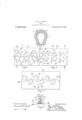
- ve-ntion consists 111 the combination Rilil arrangement 0iv parts' sst forth 1 ills 'follmving specification 'pm'tic iziriy poinied out in the claims v u Eicicirmg to the drawings: figure l TL :0 scciiuu through the rim of automobile 'lviiri smbmlyiug my invcniicn. ll 15;. 2 is u rlcwlupmcut of a port-ion of the trczul. of the 2 in; illusii'ated in Fig.
- FIG. 1 showing th s prs uiirangcmcnt 0i sh-c (:iCP]7QS5iOI1S,UF -0 Wcs therein.
- FIG. 2 illustrating still other anrangements of the grooves or (lQpl'QS SlOHS in thc ti'czu'l 2i tire.
- z, dmgz'amuuiiic View illustrating a tire embodying" my invention in connectisnwith road suzrmces irious iucliimiinns.
- the cllipticaily disposed gyros'ves 9 are a1 :ungml circumferentiaily about the periphcry of the i'iifid 7 :mcl are prefciahly uniformly spacer ⁇ ihercaiaoui.
- s'z'novos 14 are also ai'mnsrefi circumfercuiiullv about ihs pcriphcl'v of ihe i'i'sacl 7 :1 ml ihcsc grooves are psvfccily Silfllfiili; sml svmuwiiimlly placed lniemlly of sizirl plum of miuiimi.
- sz'rosvss 14- are lucatc within (he eiliuticnllv (lisuossd cleiirsssi 11s 9 and are posiiionsri Wiiliin said elii'nticallv (lismscd (l EPTQSSlOHS with their longitudinal csuim' lines B.
- said depressions are interrupted by partitions 17 and 18 arranged s vn'mietrically relatively to the central plane of rotation of said tire, thus placing the parts 1!) and entirely upon the opposite sides of said central plane of rotation, while another series of inclined grooves 21 are arranged within said elliptically disposed grooves 16 and successively incline in opposite directions relatively to said plane of rotation as for the purpose hereinbefore described relatively to the groove 14.
- grooves 27 similar to the grooves 14 and 21 of Fig 2 and 3 respecti vely. These grooves a so oblique to the central plane of rotation of the tire, successive grooves being inclined in opposite directions relatively thereto ano with their longitudinal center lines biseeting the partitions 2 and 25, respectively.
- the general operation of the device heree specifically described is as follows: A suming the surface of the road which is hemp; traversed to be level or at. right angles to the central plane of rotation of the tire 6, as iiulicated by the line 28, 5, the tire 6 will contact therewith substantially along the perimeter of the central plane of rotation, indicated by the line A, A of Fig. 2, the tire 6 will be flattened slightly by the weight of the vehicle for a distance slightly less than the length of the long diameters of the elliptically disposed grooves 9 and 16. Consequently the depressions l2 and 13 will be in contact with the surface 28 for only a ortion of their leu ths.
- a tire comprising a series of elliptically disposed grooves arranged circuinferentially of the tread of said tire, said grooves being interrupted at points upon opposite sides of their respective centers, said interruptions being located upon opposite sides of the central plane of rotation of said tire.
- a tire comprising a series of semi-elliptically disposed grooves arranged circumferentially of the tread of said tire, a portion of said series of grooves lying substantially upon one side of the central plane of rotation of said tire, and the other portion of said series of grooves lying upon the opposite side of said central plane of rotation, and a sec on d series of grooves disposed between said oppositely arranged grooves and alternately inclining in opposite directions relatively to said central plane of rotation.
Landscapes
- Engineering & Computer Science (AREA)
- Mechanical Engineering (AREA)
- Tires In General (AREA)
Description
M. P. THURP.
TIRE.
APPLICATION FILED DEC. 23, 1:112.
Patented July 22, 1913.
Like uuiucruls mics? is ut: he t cml views of c if the drawings, 6 is 121; 05 cithsi" an inner tube 01' pucuma hic fairs is. 1 .ic
ROY M. P. THORR'OF CAMBRIDGE, MASSACHUSETTS. AESIGNQR OI ONE-THIRD T0 CLAUDE E. DAVIS, OE CAMBRIDGE, MASSACHUSETTS.
TIRE.
7H g gy specificatisn of Letters latcnt. P5132111 tied Jul: 255 1591a,.
' Application filed llcccmber 533 31512. Serial No. W331i To a?! w/mm 15 may concern lie it kumvu that l, R01 subject of King (icon c V, n icliug (inn);- hiidgjgg in the county of l iiixidlcscra and fiii'ziic 0i liiussachusctts, have invent-mi ncw anal. uscij'ul. lnipruvou'wnis in Tires of which follcwing u spccificution. ihis invention relates to i mprovsmcnis in for motor vehicles and particularly 0 he nonskidding type of \ilY'G of he cutlu vm'icty, thui is in say, those having (leprcs formed in the treads tlici'cni' instcud OI prcjsciionls. In this type of tire, which includes a greafi variety of designs, the dcpi'cssioixs ()i' grooves formed in the 'yaeripherics thcreof are. CiliCHlliiOfl. to i'siaiu 2x. grip upon the asphalt, and. greasy pavenicnis ()1 any other bur-cl surfaces forming zis it were a suction which prevents the driving-wheels of the motor vehicle slipping" thereby saving power and increasiug the speed 01*. lgc vehicle. Furthermore ssici iii-0n 'pievcni's the car fi om skidding when making a turn. a
The objeci of the im cntion is to unwise a tire of the aforesaid type having depressions 0r grooves :n'ang'ed circumisrculzially along; the tread ialisreo'f and so posisimuxl Wii'h i'elaiiion 0 said bread that 6W0 :n more of said depicssions will always as in cum 1; t with and COIDDlQiGlY closed by izhc surc of he read with which said tire isiu cc tact, said depressions being (imposed.
the
hiici'nliy of said tread. 1e ve-ntion consists 111 the combination Rilil arrangement 0iv parts' sst forth 1 ills 'follmving specification 'pm'tic iziriy poinied out in the claims v u Eicicirmg to the drawings: figure l TL :0 scciiuu through the rim of automobile 'lviiri smbmlyiug my invcniicn. ll 15;. 2 is u rlcwlupmcut of a port-ion of the trczul. of the 2 in; illusii'ated in Fig. 1 showing th s prs uiirangcmcnt 0i sh-c (:iCP]7QS5iOI1S,UF -0 Wcs therein. F 3 and 3- vieu 's similar is Fig. 2 illustrating still other anrangements of the grooves or (lQpl'QS SlOHS in thc ti'czu'l 2i tire. z, dmgz'amuuiiic View illustrating a tire embodying" my invention in connectisnwith road suzrmces irious iucliimiinns.
RUll'LlillZ'E? as desired, and 7 is :1 Head which is provided iii; a. sci'ics of depressions s1" EZL'UUVQS 6 pl'i /l rll'iuliy disposed along" said (l'LHl so to bring the greater portion of helllengths 2 i one side f the venirsl plans if i'oiutiun of said U'cm'l. as indicated 1) the inc 4L, l-i iu This may he uccuur ilishvcl in many ways, but preferably the grooves S are. circularly disposed, or better still, form olliusi 9 whose longer diameters cxtcncl lill'ilfilll) relatively to said plans LUi'lilfiil, said grooves being inicrrupiefi by partitions 10 and 11 upon opposite siclcs of the center of said ellipses anilupon opposisc si (198 (if said plane of mutation, thus forming two subsfan't-ially !1l(.l1CLllElP grcovcs 12 and 13. A greater portion of the groove 12 is located 031 one S'lClG 02f. saicl plans, While H10 gneaier portion of the groove 13 located on the opnnsiis siclc of said plans. The cllipticaily disposed gyros'ves 9 are a1 :ungml circumferentiaily about the periphcry of the i'iifid 7 :mcl are prefciahly uniformly spacer} ihercaiaoui. Another series if s'z'novos 14 are also ai'mnsrefi circumfercuiiullv about ihs pcriphcl'v of ihe i'i'sacl 7 :1 ml ihcsc grooves are psvfccily Silfllfiili; sml svmuwiiimlly placed lniemlly of sizirl plum of miuiimi. ihv lo'ng' ii'ucliuul ccnicz linss c said xzr'oovcs hciug oblique to ssici hms i urihcrumrc said sz'rosvss 14- are lucatc within (he eiliuticnllv (lisuossd cleiirsssi 11s 9 and are posiiionsri Wiiliin said elii'nticallv (lismscd (l EPTQSSlOHS with their longitudinal csuim' lines B. B passing flirnurrh the par iii'inns 10 mid 11 substantially midway ihm'eo'f. Said depressions l4 iez'minats at rlisi'anccs inside 0'! said psi'fifions thus pus siding" substuniial amount (if material bei'wesn the op osii'c cufis of suicl dc c-rcssicns 1% and the ends 01" (he (lsprsssicns "i2 incl 13.
in (ii-tier that the pressure on the tire, ('3 laici'ullv rciziiiveljv is iii-c central plane, s? l'fii'fltifin thereof may be evenly imlancecl in OD'DOSliQ (lircc inns, the angle of the long tudinal centei' lines of tlieciebressinus 14 alternate tmvsrcl one side and iiheu "H'lWfi-IFl other sicls of said plane of lion and the pariiiions 1G anti 11 of thcii respcciii'vc sllibticaliy clisposecl grooves sarmuseii accordingly.
Rcfcming to i i l'iz'zjvs. s hcwn unc'tlisr wrung-emails of ihe nuri'iiions. in i'hs tread is Drcvificcl 'Wi'ii grooves s1" cicprcssiciis 1,6 which. are "prci erahly elliptically disposed as in Fig. 2. In this case however said depressions are interrupted by partitions 17 and 18 arranged s vn'mietrically relatively to the central plane of rotation of said tire, thus placing the parts 1!) and entirely upon the opposite sides of said central plane of rotation, while another series of inclined grooves 21 are arranged within said elliptically disposed grooves 16 and successively incline in opposite directions relatively to said plane of rotation as for the purpose hereinbefore described relatively to the groove 14.
In F 4 I have illustrated still another out of the depression circumferentially ot' the tire tread '7. in this case a zip; my groove torined progressing laterally from side to side of said tread circumferentiall y thereof and forming reverse curves 22 and 23, these curves being interrupted by partitions and upon opposite sides of the central plane of rotation of the tread 26.
Intermediate the several sections of said ziggroove are provided grooves 27 similar to the grooves 14 and 21 of Fig 2 and 3 respecti vely. These grooves a so oblique to the central plane of rotation of the tire, successive grooves being inclined in opposite directions relatively thereto ano with their longitudinal center lines biseeting the partitions 2 and 25, respectively.
In 5 l have illustrated the tire 6 contact with surfaces inclining at various relatively o the central plane of rota- :aid tire to more clearly illustrate the t the depressions hereinbeiore shown and lQSLlllJEd.
The general operation of the device heree specifically described is as follows: A suming the surface of the road which is hemp; traversed to be level or at. right angles to the central plane of rotation of the tire 6, as iiulicated by the line 28, 5, the tire 6 will contact therewith substantially along the perimeter of the central plane of rotation, indicated by the line A, A of Fig. 2, the tire 6 will be flattened slightly by the weight of the vehicle for a distance slightly less than the length of the long diameters of the elliptically disposed grooves 9 and 16. Consequently the depressions l2 and 13 will be in contact with the surface 28 for only a ortion of their leu ths. while the de res P c P sion 14% will be entirely covered and as the tire rolls along over the surface 28 with the successive depressions l4 coining in contact therewith, the air will be forced from said depressions and consequently form a suction F which causes said t e to -ly 'rip the sur face road thereby prevent ng lipping or skidding. By arranging said depressions 1d oblique to the central plane of rotation, as hereinbefore stated, the flattening effect of the tire tread in either the lateral or circumferential direction will not cause the opposite sides thereof to draw together to any appreciable degree.
There are times when the tread of the tire 6 will engage a surface which is inclined at an angle to the plane of rotation thereof as 29 and in which cases the contacting area or" the tread of the tire will be shifted laterally until one or the other of the depressions 12 and 13, 19 and 20. or 22 and 23 will be entirely covered and sealed, owing to the arrangements of the partitions 10 and 11, 17 and 18 and 2 t and of Figs. 2, and l re spectively, as hereinbefore described, and thereby a continuous gripping of the surface will he provided. The depressions 1 t, 21 and 2? always providing a suction for the tread and being assistedby either the depressions 12, 19 and 23 or 13, 20 and 22 as the use may be according to the inclination of the surface of the road.
In the foregoing description and in the following claims the word elliptically has been frequently used. It is not-however in tended to exclude thereby the limiting form of an ellipse which is a circle.
Having thus described my invention, what I claim and desire by Lettes Patent to secure is:
l. A tire comprising a series of elliptically disposed grooves arranged circuinferentially of the tread of said tire, said grooves being interrupted at points upon opposite sides of their respective centers, said interruptions being located upon opposite sides of the central plane of rotation of said tire.
2. A tire comprising a series of semi-elliptically disposed grooves arranged circumferentially of the tread of said tire, a portion of said series of grooves lying substantially upon one side of the central plane of rotation of said tire, and the other portion of said series of grooves lying upon the opposite side of said central plane of rotation, and a sec on d series of grooves disposed between said oppositely arranged grooves and alternately inclining in opposite directions relatively to said central plane of rotation.
In testimony whereof I have hereunto set my hand in presence of two subscribingwitnesses.
ROY M. I. THORP.
lOO
Priority Applications (1)
| Application Number | Priority Date | Filing Date | Title |
|---|---|---|---|
| US73811412A US1068025A (en) | 1912-12-23 | 1912-12-23 | Tire. |
Applications Claiming Priority (1)
| Application Number | Priority Date | Filing Date | Title |
|---|---|---|---|
| US73811412A US1068025A (en) | 1912-12-23 | 1912-12-23 | Tire. |
Publications (1)
| Publication Number | Publication Date |
|---|---|
| US1068025A true US1068025A (en) | 1913-07-22 |
Family
ID=3136266
Family Applications (1)
| Application Number | Title | Priority Date | Filing Date |
|---|---|---|---|
| US73811412A Expired - Lifetime US1068025A (en) | 1912-12-23 | 1912-12-23 | Tire. |
Country Status (1)
| Country | Link |
|---|---|
| US (1) | US1068025A (en) |
-
1912
- 1912-12-23 US US73811412A patent/US1068025A/en not_active Expired - Lifetime
Similar Documents
| Publication | Publication Date | Title |
|---|---|---|
| US3286756A (en) | Automobile tire | |
| US4884607A (en) | Pneumatic tire tread pattern with lateral grooves having increasing groove angle towards shoulders | |
| CA2064937A1 (en) | Pneumatic safety tire | |
| JP3517404B2 (en) | studless tire | |
| IE66263B1 (en) | "Tread for heavy-vehicle tire in which the central ribs are provided with inclined incisicons" | |
| US20030192634A1 (en) | Tire used in winter | |
| US2154290A (en) | Tread for pneumatic tires | |
| JP2020049956A (en) | tire | |
| JPH09183303A (en) | Pneumatic tire | |
| JPH061119A (en) | Pneumatic tires for ice and snow roads | |
| JPH0487806A (en) | Block for pneumatic tire | |
| JP2000158915A (en) | Pneumatic tire | |
| JP2012091564A (en) | Tire | |
| JP4753342B2 (en) | Pneumatic radial tire | |
| JPH04215504A (en) | Pneumatic radial tire | |
| JP4487668B2 (en) | Pneumatic stud tire | |
| US582194A (en) | Pneumatic tire | |
| US945396A (en) | Automobile-tire. | |
| US781573A (en) | Traction-wheel. | |
| JPH02179509A (en) | Pneumatic tire | |
| US957168A (en) | Tire. | |
| US1142909A (en) | Antiskidding device. | |
| JP4472131B2 (en) | Pneumatic tire | |
| US650907A (en) | Bicycle-tire. | |
| US957165A (en) | Antiskidding-tire. |