US10675761B2 - Mode architecture for general purpose robotics - Google Patents
Mode architecture for general purpose robotics Download PDFInfo
- Publication number
- US10675761B2 US10675761B2 US15/785,040 US201715785040A US10675761B2 US 10675761 B2 US10675761 B2 US 10675761B2 US 201715785040 A US201715785040 A US 201715785040A US 10675761 B2 US10675761 B2 US 10675761B2
- Authority
- US
- United States
- Prior art keywords
- mode
- robot
- robotic device
- instructions
- location
- Prior art date
- Legal status (The legal status is an assumption and is not a legal conclusion. Google has not performed a legal analysis and makes no representation as to the accuracy of the status listed.)
- Active, expires
Links
Images


Classifications
-
- B—PERFORMING OPERATIONS; TRANSPORTING
- B25—HAND TOOLS; PORTABLE POWER-DRIVEN TOOLS; MANIPULATORS
- B25J—MANIPULATORS; CHAMBERS PROVIDED WITH MANIPULATION DEVICES
- B25J9/00—Programme-controlled manipulators
- B25J9/16—Programme controls
- B25J9/1679—Programme controls characterised by the tasks executed
- B25J9/1682—Dual arm manipulator; Coordination of several manipulators
-
- B—PERFORMING OPERATIONS; TRANSPORTING
- B25—HAND TOOLS; PORTABLE POWER-DRIVEN TOOLS; MANIPULATORS
- B25J—MANIPULATORS; CHAMBERS PROVIDED WITH MANIPULATION DEVICES
- B25J9/00—Programme-controlled manipulators
- B25J9/16—Programme controls
- B25J9/1656—Programme controls characterised by programming, planning systems for manipulators
- B25J9/1658—Programme controls characterised by programming, planning systems for manipulators characterised by programming language
-
- G—PHYSICS
- G05—CONTROLLING; REGULATING
- G05B—CONTROL OR REGULATING SYSTEMS IN GENERAL; FUNCTIONAL ELEMENTS OF SUCH SYSTEMS; MONITORING OR TESTING ARRANGEMENTS FOR SUCH SYSTEMS OR ELEMENTS
- G05B19/00—Programme-control systems
- G05B19/02—Programme-control systems electric
- G05B19/04—Programme control other than numerical control, i.e. in sequence controllers or logic controllers
- G05B19/042—Programme control other than numerical control, i.e. in sequence controllers or logic controllers using digital processors
- G05B19/0426—Programming the control sequence
-
- G—PHYSICS
- G05—CONTROLLING; REGULATING
- G05B—CONTROL OR REGULATING SYSTEMS IN GENERAL; FUNCTIONAL ELEMENTS OF SUCH SYSTEMS; MONITORING OR TESTING ARRANGEMENTS FOR SUCH SYSTEMS OR ELEMENTS
- G05B2219/00—Program-control systems
- G05B2219/30—Nc systems
- G05B2219/31—From computer integrated manufacturing till monitoring
- G05B2219/31076—Controller for cell, for robot motion, for supervision
-
- G—PHYSICS
- G05—CONTROLLING; REGULATING
- G05B—CONTROL OR REGULATING SYSTEMS IN GENERAL; FUNCTIONAL ELEMENTS OF SUCH SYSTEMS; MONITORING OR TESTING ARRANGEMENTS FOR SUCH SYSTEMS OR ELEMENTS
- G05B2219/00—Program-control systems
- G05B2219/30—Nc systems
- G05B2219/40—Robotics, robotics mapping to robotics vision
- G05B2219/40397—Programming language for robots, universal, user oriented
Definitions
- Robots are machines having both electrical and mechanical systems that allow the robot to be controllably managed to perform intended actions.
- a robotic arm is a type of robot implemented as a mechanical arm, where the robotic arm may be controllably manipulated into a range of different positions and motions.
- the robotic arm may further include an end effector or gripping mechanism (such as a robotic hand) which can be used to pick up, hold, and release objects to be manipulated.
- Robots may be used in any environment in which it is advantageous to have a mechanical entity automatically handle a task, especially a task that requires precise, repeatable manipulations of objects in the environment.
- modern manufacturing facilities often use a variety of robot devices at different stages of the manufacturing process to make, assemble, test, and/or package items being manufactured in the facility.
- Robots typically include some sort of control system to control the operation of the robot.
- Computer code is often employed to guide the operation of the robot, where the computer code is embedded or otherwise loaded onto the robot, and execution of the computer code causes the robot to perform its intended operations.
- FIG. 1A shows an example robotic arm 104 whose operation is controlled by a robot controller 102 a .
- a control computer 124 may be used to interface with the robot controller 102 a , where the control computer has a user interface to allow a user to send control instructions to the robot (such as “start” and “stop” instructions).
- the control computer 124 may also include software pertaining to the analysis/processing of data from the robot system.
- robotic arm is employed by an organization as a test platform to perform a manufacturing function, but once the proof-of-concept for the manufacturing task has been approved, the organization would like to move to another type of robotic mechanism (such as a conveyor belt) to perform the manufacturing task.
- the robotic arm is often used to create and refine a given manufacturing task, given the wide range of control that can be achieved over the motions and articulations of the arm.
- robotic arms are comparatively more complicated and expensive compared to simpler and more specialized devices such as conveyor belts.
- the organization may seek to implement that same task on the factory floor using the simpler device, such as conveyor belt 106 of FIG. 1B .
- each robot manufacturer typically provides its own unique programming environment to allow its customers to create and install a software application to control the operation of the robot.
- the robot manufacturer may include a toolkit of functionality that may be called from the software application.
- the software may be implemented using a general purpose programming language (such as Java or C), and on other cases, a specialty software language may need to be employed to create the software application.
- the custom computer code may include information that is considered sensitive and/or proprietary by the organization.
- the robot may be employed to engage in a manufacturing process where the manufacturing/operating processing and/or conditions are embedded into the operating software, and that information about manufacturing process or operating conditions are considered trade secrets.
- a third party such as a third party contract manufacturer
- a security risk may exist with respect to the organization's trade secretes since the third party would potentially have access to the robot and its custom computer code.
- Embodiments herein provide an improved method, system, and apparatus to generate an architecture to implement execution modes on robotic systems.
- a mode execution module is provided to execute execution modes on the robotic system.
- a system in one embodiment, includes an execution module that receives software instructions in a normalized programming language.
- the system also includes an interface having a translation layer that converts the software instructions from the normalized language into robot-specific instructions that operate in a particular robotic system.
- the system further includes a controller that is communicatively coupled to the interface, wherein the controller receives the robot-specific instructions.
- the system includes a robotic device that is operatively controlled by the controller by execution of the robot-specific instructions.
- the software instructions include one or more execution modes corresponding to at least one of an enter mode, an exit mode, and a trigger mode.
- the system may also include a second interface that converts the software instructions from the normalized language into second robot-specific instructions that are sent to a second controller to operatively control a second robotic device, where the second robotic device corresponds to a different type of device from the robot device.
- the second robot-specific instructions for the second robotic device may correspond to a different set of programming instructions from the robot-specific instructions for the robotic device.
- the execution module includes a mode selection module, a mode instruction processing module, and a controller interface module.
- the mode selection module may select a specific mode based on a mode selection instruction.
- the mode instruction processing module may determine a specific combination or sequence of mode instructions to be issued to the controller to perform a desired operation.
- the controller interface module may issue one or more API calls corresponding to the particular robotic system that are sent to the controller. At least one of safe entry points or safe exit points may be established for entry or exit of modes.
- the system also includes a rulebase having a set of rules that identifies acceptable or unacceptable sequences of modes for one or more robotic systems.
- the set of rules may be accessed to determine where a selected mode of operation for the robotic device is acceptable as a next mode of operation.
- the controller may include a real-time operating system that controls a motor driver to operate the robotic device.
- the execution module may be loaded as an application onto the controller.
- the controller includes both a real-time operating system (RTOS) and a user-space operating system (OS).
- RTOS may control a motor driver to operate the robotic device.
- the user-space OS may provide user-specified commands to the RTOS.
- the interface may issue API calls that are understandable by a manufacturer-provided robot application layer within the user-space OS to execute the software instructions.
- the controller includes a thin interface layer and mode control functionality is located within a mode control/select layer that is located at a control application at a control computer.
- the interface may have functionality to communicate with the mode control/select layer and to deliver the robot-specific instructions to a RTOS.
- the execution module may be implemented as a loadable kernel module (LKM) within a RTOS at the controller.
- LLM loadable kernel module
- a method in another embodiment, includes receiving software instructions for a robotic device in a normalized programming language. The method also includes converting the software instructions from the normalized language into robot-specific instructions that operate in a particular robotic system corresponding to the robotic device. The method further includes controlling the robotic device by execution of the robot-specific instructions.
- the software instructions include one or more execution modes corresponding to at least one of an enter mode, an exit mode, and a trigger mode.
- the method also includes identifying a selection of a selected mode.
- the method further includes determining whether the selected mode is acceptable in light of a current state of the robotic device.
- the method includes placing the robotic device into a safe exit state or location for a current mode if the selected mode is acceptable.
- the method includes stopping the current mode.
- the method also includes placing the robotic device into a safe entry state or location for the selected mode.
- the method further includes starting the selected mode.
- a set of rules in a rulebase are accessed to determine where the selected mode for the robotic device is acceptable as a next mode of operation. If the selected mode is not acceptable, then a determination may be made of an alternative instruction that is an acceptable alternative to the selected mode.
- the alternative instruction may be determined by at least one of checking the rulebase, performing manual intervention, or using a machine learning system.
- the safe exit state or location may be different from the safe entry state or location. Between different modes, the safe exit state or location or safe entry state or location for a first mode may be different from the safe exit state or location or safe entry state or location for a second mode.
- a waiting period is entered for a trigger.
- the robotic device may perform a predefined mode function corresponding to the trigger.
- the software instructions may be converted from the normalized language into robot-specific instructions by generating a set of API calls that correspond to the particular robotic system corresponding to the robotic device.
- a computer program product embodied on a computer readable medium, the computer readable medium having stored thereon a sequence of instructions which, when executed by a processor causes the processor to execute a method including receiving software instructions for a robotic device in a normalized programming language. The method also includes converting the software instructions from the normalized language into robot-specific instructions that operate in a particular robotic system corresponding to the robotic device. The method further includes controlling the robotic device by execution of the robot-specific instructions.
- the software instructions includes one or more execution modes corresponding to at least one of an enter mode, an exit mode, and a trigger mode.
- the sequence of instructions further executes the method also including identifying a selection of a selected mode.
- the method further includes determining whether the selected mode is acceptable in light of a current state of the robotic device.
- the method includes placing the robotic device into a safe exit state or location for a current mode if the selected mode is acceptable.
- the method includes stopping the current mode.
- the method also includes placing the robotic device into a safe entry state or location for the selected mode.
- the method further includes starting the selected mode.
- a set of rules in a rulebase are accessed to determine where the selected mode for the robotic device is acceptable as a next mode of operation. If the selected mode is not acceptable, then a determination may be made of an alternative instruction that is an acceptable alternative to the selected mode.
- the alternative instruction may be determined by at least one of checking the rulebase, performing manual intervention, or using a machine learning system.
- the safe exit state or location may be different from the safe entry state or location. Between different modes, the safe exit state or location or safe entry state or location for a first mode may be different from the safe exit state or location or safe entry state or location for a second mode.
- a waiting period is entered for a trigger.
- the robotic device may perform a predefined mode function corresponding to the trigger.
- the software instructions may be converted from the normalized language into robot-specific instructions by generating a set of API calls that correspond to the particular robotic system corresponding to the robotic device.
- FIGS. 1A and 1B illustrate example robot systems.
- FIG. 2 illustrates an example robotic control architecture according to some embodiments.
- FIG. 3 illustrates the internal architecture of the mode execution module according to some embodiments.
- FIG. 4 shows a flowchart of an approach to implement a mode change operation according to some embodiments.
- FIG. 5 shows a flowchart of an approach to implement a mode instruction processing module according to some embodiments.
- FIG. 6 shows a flowchart of an approach to implement a controller interface module according to some embodiments.
- FIGS. 7A-D illustrate example robot architectures according to some embodiments.
- FIG. 8 illustrates an example robot architecture receiving client input according to some embodiments.
- FIG. 9 shows a flowchart of an approach to implement a mode change operation according to some embodiments.
- FIG. 10 illustrates possible robot systems that can be used to perform camera calibration according to some embodiments.
- FIG. 11 depicts a computerized system on which some embodiments can be implemented.
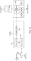
- FIG. 2 illustrates an example robotic control architecture 100 according to some embodiments.
- a mode execution module 105 (which may also be referred to herein as either a “mode runner” module or “mode wrapper” module) is provided to execute execution modes (also referred to herein as “modes”) on any of several different robotic systems, such as robotic arm 104 or conveyor belt 106 .
- the modes correspond to any sequence of robotic instructions that is coded into a programming language that is recognizable by the mode execution module 105 .
- the modes are coded with a normalized set of API (applications programming interface) calls that are recognizable by the mode execution module 105 .
- a mode defines a “enter mode” and an “exit mode” method. These methods are called to allow the mode to enter the desired workspace safely and return the robot to a safe state as needed. This means that the modes do not need to know anything about each other and the “mode runner” that selects which mode is currently running does not need to know anything about what the modes are doing. This also means modes can be added or removed from the set of available modes without having to modify any other code.
- a mode may also define an “on trigger” method that signals it should do something.
- Interfaces are defined for each of the specific robot controllers that may be employed within the architecture 100 .
- Each interface includes a translation layer to convert instructions within the modes that are in a normalized language into the specific instructions that are needed to implement a desired action within a particular robotic system. For example, when a given robotic system exposes its functionality using a set of API calls, the interface may operate to translate mode instructions into the appropriate API call.
- a first interface 112 a is defined to interact with controller 102 a for robotic arm 104
- a second interface 112 b is defined to interact with controller 102 b for conveyor belt 106 .
- a user at control computer 124 operates a controller application 126 to manage the operations of one or more of the robot systems.
- the controller application 126 relays commands to the mode execution module 105 to execute any of one or more modes 1 , 2 , . . . , n on a given robot system.
- the properly formatted instructions for the selected mode(s) are relayed to the appropriate controller for the target robot system using the interface that is specifically developed for the targeted robot system.
- This architecture allows the user to quickly develop robot applications that connect to various pieces of software. This is facilitated by defining a very limited set of commands (e.g., normalized commands) that can be easily extended as new modes are added, without being so tied to specific robot hardware systems. In this way, an organization can perform initial development activities using a first robot system, and then very quickly leverage the existing codebase of the modes to transition to a new robot system for production purposes.
- commands e.g., normalized commands
- the current approach also allows limited safe access to the robot to any users within the organization.
- the robot is a potentially dangerous piece of hardware that is capable of destroying itself and things around it at high speed, but it is also a very useful tool to have around.
- the present system implements a limited set of commands that users with no training in robot programming and minimal safety training could send to the robot while minimizing or eliminating the risk of breaking anything in the area of the robot.
- the modes in this case limit the set of actions the robot can take to a well-known set of actions that can be vetted by a competent robot programmer without being forced to limit the exact sequence of events that the novice robot user might attempt.
- the modes can be executed very safely since the mode execution module acts as a “wrapper” around each of the modes, and the mode execution module includes oversight functionality to ensure that the executing modes do not perform operations in an unsafe or inappropriate manner.
- the mode execution module operates to make sure any start of a new mode causes the previously executing mode for a given system to exit in a safe and appropriate robotic state, and also ensure that the new mode does not start until the robot is in a safe starting state.
- the computer code to operate a robot controller may include information that is considered sensitive and/or proprietary.
- the present approach provides an architecture that allows for flexible robot routine development while limiting the communication protocol to a small set of commands. This permits the robot to be treated as a “black box” from the perspective of the control computer, so that the proprietary or sensitive information is maintained at the control computer instead of at the robotic system. This is particularly important since many robotic systems run on rudimentary or antiquated operating systems that may be vulnerable to outside attackers, while the control computers may be implemented using any computing system having the most up-to-date security controls.
- Another advantage of the current approach is that it allows an organization to efficiently implement competing ideas for the same robot action and run experiments where data is collected in exactly the same way, varying only by the mode that is selected. This will allow an organization to run head-to-head experiments in a way that was previously unavailable.
- FIG. 3 illustrates the internal architecture of the mode execution module 305 according to some embodiments.
- the mode execution module 305 may operate to select and execute any number of different modes. While this figure illustratively shows two modes (Mode A and Mode B), it is noted that any number of different modes may be loaded and/or executed by the mode execution module in various embodiments.
- a control computer may operate the mode execution module.
- a “change mode” command may be provided to specify the desired mode the robot should select.
- a “mode select” function is performed by the mode execution module to select the mode having the Mode ID/name provided as part of the change mode command.
- a “trigger” command can be provided to instruct the selected mode to perform some action (see FIGS. 8 and 9 ).
- the “Start” and “Stop” commands are provided to start and stop the execution of the selected mode or actions within the mode. It is noted that the details of what a specific mode does when triggered are dependent upon the program code that is configured within the mode software.
- the individual instructions from the current mode are sent for execution to a mode instruction processing module 330 . It is this module that receives the individual instruction from the current mode, and issues those instructions as appropriate to the robot controller. This module includes a set of configuration settings and/or rules that define how and whether the mode instructions, or specific combination/sequence of the mode instructions, are to be issued to the robot controller to perform a desired operation. It is this approach to process the instructions that allows a user to create a generic mode using the limited and normalized set of commands, and yet still be able to have those limited commands be safely useable with a wide range of target robot systems.
- the processed instructions are sent to the controller interface module 332 for delivery to the robot system, e.g., to the specific application or RTOS (real time operating system) that is configured at the robot system to receive instructions.
- the controller interface module 332 issues the appropriate API calls to effect the desired operations for the modes.
- Various types of messages may be provided from the mode execution module 305 to the control computer. For example, status messages may be provided to indicate whether the robot is currently moving or if the robot is currently stopped. In addition, the identity of the current mode may be provided upon the request of the control computer. To the extent any errors are detected, error messages and/or error codes may be sent to the control computer. The errors may relate to errors caused by the mode execution, or may pertain to the status/operation of the robot itself.
- controls are put into place to ensure that a safe transition can occur between the old mode and the new mode, e.g., by implementing safe entry and exit points for mode changes. This allows, for example, the user to implement and test different combinations or ordering of modes without fear of causing damage to the robot machinery.
- FIG. 4 shows a flowchart of an approach to implement the mode change operation to implement safe mode-to-mode transitions according to some embodiments.
- a mode change operation is received for processing that includes the identifier of the new mode.
- Any type of identifier may be suitably used within the system to identify modes, including for example, mode names, mode ID values, and/or mode file/pathnames.
- an optional step at 404 is to check whether the selected next mode is acceptable as the next mode.
- This step may be implemented, for example, by checking against a rulebase having a set of rules that identifies the acceptable and/or unacceptable sequences of modes for intended robotic systems.
- the rules within the rulebase may be provided from any suitable source, e.g., from the robot manufacturer, from the provider of the mode wrapper/runner software, from users/operators, open source, or any combination thereof.
- the rules may be modified over time, e.g., from editing performed by users/operators and/or by using a machine learning/expert system infrastructure to allow automated learning over time of acceptable mode combinations.
- next mode is an acceptable mode
- the robot device is placed into a safe exit location/state for the current mode.
- the same consistent exit location/state is defined for all modes that operate for a given robot system, e.g., stopping the motion of the robot and placing the robot into a designated location/position.
- certain modes can be configured to have an exit location/state that is individual to that mode.
- the robot device is placed into a safe starting state for the new mode.
- some systems may include a single universal starting location/state that is applicable for all modes.
- some or all of the modes may be configured to have individualized safe start locations/states.
- safe start (and possibly stop) locations/states correspond to locations with a large amount of free space/volume around them, such that they can move to/from other start/stop locations without collisions en route.
- Safe start/stop locations/states may be distinct within a specific mode, as one may want to start an operation (e.g., camera calibration pass) with the robot/camera starting at a location (e.g., one side of a target) and stopping at another location (e.g., at the other side of the target). They may also differ between modes. For example, in Mode A, the operation may be placing an object in bin A, and so Mode A may have a stop space positioned above bin A, and then Mode B may involve picking an object from bin B, so its start space may be above bin B. Once the robot has been placed into a state that is safe to start the mode, then at 411 , the new mode is started.
- Mode A the operation may be placing an object in bin A, and so Mode A may have a stop space positioned above bin A, and then Mode B may involve picking an object from bin B, so its start space may be above bin B.
- FIG. 5 shows a flowchart of an approach to implement the mode instruction processing module 305 of FIG. 3 .
- the individual instructions from the executing mode are sent for execution to the mode instruction processing module 305 .
- the mode instruction processing module 305 is responsible for implementing the appropriate instructions to the robot device to implement the desired functionality of the mode instructions.
- the mode instruction is received for execution, where the instruction corresponds to a selected command from a defined set of commands that are available to be placed into the mode.
- the current state of the robot device is then checked at 504 .
- a set of rules from within a rulebase is checked to determine the applicability of a given mode instruction for a given robot state. For example, if the user includes a command in a mode that is actually intended to be used for a different robot system than is currently running, then this may present a compatibility problem for the mode instruction.
- the instruction is sent to the robot device for execution. If the mode instruction is not acceptable, then at 508 , an optional step can be taken to determine if there is an alternative instruction that is an acceptable alternative to the mode instruction that has been received. Any suitable approach can be taken to identify an acceptable alternative, e.g., by checking the rulebase, with manual intervention, or using a machine learning/expert system. If an acceptable alternative is identified, then the instruction is modified as appropriate at 510 , and the modified instruction is then sent at 512 to the robot device for execution.
- the mode instruction is found to be unacceptable at 506 and, optionally, no acceptable alternative to the mode instruction is identified at 508 , then the instruction is not executed. Instead, at 514 , error handling is performed, e.g., to send an error message indicating the execution problem with the mode instructions.
- FIG. 6 shows a flowchart of an approach to implement the controller interface module 332 .
- the processed mode instructions are received for deliver to the robot controller.
- controller-specific instructions are generated with appropriate execution parameters.
- the robot system may be controllable using API calls that have been exposed by the robot manufacturer.
- the controller interface module 332 issues the appropriate API calls to effect the desired operations for the mode instructions.
- the API calls are then sent to the robot system for execution.
- FIG. 7A shows an example architecture for a robotic arm 704 whose operation is controlled by a robot controller 702 .
- Controller 702 includes a real-time operating system (RTOS) 706 that controls a motor driver 708 to control the operation of the robot arm 704 .
- RTOS real-time operating system
- the mode interface module 705 may be loaded as an application onto the controller 704 .
- the mode interface module 705 includes a mode control portion 714 and an interface portion 712 .
- a control computer 724 may include a control application 726 to interact with the mode interface module 705 .
- a user may use a user interface of the control application 726 at the control computer 724 to send control commands to the mode control portion 714 to select one of the modes 1 , 2 , . . . , n, and to provide specific commands such as “trigger”, “start” and “stop” to the selected mode.
- FIG. 7B shows an alternative architecture, where the controller 702 further includes a user-space OS 707 to provide user-specified commands to the RTOS 706 .
- the interface portion 712 of the mode interface module 705 will interface with the user space OS 707 to provide the instructions to control the robot arm 704 .
- the interface portion 712 will issue the appropriate API calls that are understandable by a manufacturer-provided robot application layer within the user-space OS to execute the desired commands.
- FIG. 7C shows another example architecture, where only a very thin interface layer 705 a is located within the controller 704 .
- the majority of the mode control functionality is located within the mode control/select layer 705 b that is located at the control application 726 at the control computer 724 .
- the interface layer 705 a only includes the minimum amount of functionality necessary to communicate with the mode control/select layer 705 b , and to deliver/translate the robot-system specific commands to the RTOS 706 . This approach provides the maximum amount of separation for any proprietary information between the robot system and the control system.
- FIG. 7D shows yet another example architecture, where the mode execution module 715 is implemented as a loadable kernel module (LKM) within the RTOS 706 at the controller 702 .
- LKM is the specific type of module that can be loaded to extend the functionality of a kernel (such as a Linux kernel).
- a kernel such as a Linux kernel.
- an insmod call and/or a modprobe call is made that loads the OS module into the kernel.
- the LKM's initialization routine is executed right after it loads the LKM, where as part of initialization, the OS module loaded into the kernel will initialize and open up, for example, a named pipe to facilitate communications between the Real-time OS 706 and the LKM.
- This approach allows for a very high level of integration between the functions of the mode execution module 715 and the operations of the controller 702 .
- FIG. 8 shows an example architecture for a robotic arm 804 whose operation is controlled by a robot controller 702 using input from a client.
- the client may be a user or another computing system.
- Controller 702 includes a mode runner 805 , which may be operated in modes 1 to n.
- the controller 702 can receive one or more mode change requests, triggers, and, optionally, data for use with a particular triggered function.
- FIG. 9 shows a flowchart of an approach to implement the mode change operation to implement safe mode-to-mode transitions according to some embodiments.
- a mode change operation is received for processing that includes the identifier of the new mode.
- Any type of identifier may be suitably used within the system to identify modes, including for example, mode names, mode ID values, and/or mode file/pathnames.
- an optional step at 904 is to check whether the selected next mode is acceptable as the next mode.
- This step may be implemented, for example, by checking against a rulebase having a set of rules that identifies the acceptable and/or unacceptable sequences of modes for intended robotic systems.
- the rules within the rulebase may be provided from any suitable source, e.g., from the robot manufacturer, from the provider of the mode wrapper/runner software, from users/operators, open source, or any combination thereof.
- the rules may be modified over time, e.g., from editing performed by users/operators and/or by using a machine learning/expert system infrastructure to allow automated learning over time of acceptable mode combinations.
- next mode is an acceptable mode
- the robot device is placed into a safe exit location/state for the current mode.
- the same consistent exit location/state is defined for all modes that operate for a given robot system, e.g., stopping the motion of the robot and placing the robot into a designated location/position.
- certain modes can be configured to have an exit location/state that is individual to that mode.
- the robot device is placed into a safe starting state for the new mode.
- some systems may include a single universal starting location/state that is applicable for all modes.
- some or all of the modes may be configured to have individualized safe start locations/states.
- safe start (and possibly stop) locations/states correspond to locations with a large amount of free space/volume around them, such that they can move to/from other start/stop locations without collisions en route.
- Safe start/stop locations/states may be distinct within a specific mode, as one may want to start an operation (e.g., camera calibration pass) with the robot/camera starting at a location (e.g., one side of a target) and stopping at another location (e.g., at the other side of the target). They may also differ between modes. For example, in Mode A, the operation may be placing an object in bin A, and so Mode A may have a stop space positioned above bin A, and then Mode B may involve picking an object from bin B, so its start space may be above bin B. Once the robot has been placed into a state that is safe to start the mode, then at 912 , the new mode is started.
- Mode A the operation may be placing an object in bin A, and so Mode A may have a stop space positioned above bin A, and then Mode B may involve picking an object from bin B, so its start space may be above bin B.
- the system waits to receive a trigger (e.g., from a client) at 914 .
- the controller may also optionally receive trigger data for use in a predefined mode function corresponding to the trigger received at 914 .
- the robot will perform the predefined mode function corresponding to the trigger and, optionally, the trigger data. Examples of predefined mode functions include: (1) moving a portion of the robot through points A, B, C, etc. and (2) moving a portion of the robot to point D, which is defined in the optional trigger data.
- the system waits for the next input (e.g., from a client). If the next input is a mode change, the process returns to 900 . If the next input is a trigger/trigger command, the process returns to 914 . If the next input is an end signal, the process ends at 920 .
- the present invention may be applied to implement robotics in any desired operating environment or purpose.
- inventive robot architecture is employed to perform device calibration, data collection, and device testing for machine vision devices (e.g., cameras).
- a camera is a device that is often employed to capture images or video.
- the data captured by the camera is used in a variety of different purposes and contexts.
- a wearable device may include one or more onboard cameras to provide image data for the surrounding environment around the user of that wearable device.
- One example is the stereoscopic wearable glasses that features two forward-oriented cameras configured to capture images for an augmented reality presentation to the user through stereoscopic displays.
- the wearable glasses may also include backwards-oriented cameras to capture images of the user's eyes.
- the camera calibration process determines the true parameters of a camera device that produces an image, which allows for determination of calibration data of the camera such as intrinsic parameters and extrinsic parameters.
- the intrinsic parameters include, but are not limited to, focal point, focal length, principal point, and distortion coefficients.
- the extrinsic parameters include, but are not limited to, positional relationships between multiple cameras, and translational and rotational offsets between sensors.
- FIG. 10 illustrates two possible robot systems that can be used to perform camera calibration, where a first system uses a robot arm to position the camera into the different positions and the second approach uses a conveyor belt to move the camera(s). This situation may arise, for example, where the robot arm system is initially employed to develop the general flow and parameters of the calibration process, while a later transition occurs to subsequently use the conveyor belt system in a production setting.
- the embodiments of the present invention address these problems by implementing a mode execution module 1005 to execute the different modes that are executed on each of the robot systems.
- the control application interacts with the mode execution module 1005 to select the appropriate mode for execution.
- Specific interfaces are developed to provide the correct commands that can be understood by the individual robot systems.
- interface 1004 a provides the appropriate commands to controller 1002 a control the operation of the robot arm system
- interface 1004 b provides the appropriate commands to controller 1002 b control the operation of the conveyor belt system.
- Modes can be developed where some of the modes are usable across multiple robot platforms, while other modes are only usable with specific robot systems.
- a multi-camera approach can be employed for performing calibration, where the conveyer belt includes multiple placement positions for multiple cameras, and there are multiple cameras that undergo calibration at any given moment in time. Each of the cameras are located at a designated position, spaced apart from one another at a specified distance, with their image capture direction facing the target.
- One or more modes can be developed specific to the conveyor belt system to shift the conveyor belt to designated positions for the cameras to take an image from those positions.
- the mode(s) implement a move-pause-image capture-move again cycle that is repeated until each camera has taken an image from each designated position.
- Another possible mode is an “expedited teach” mode—where a technician teaches a robot the endpoints to a grid, and the robot can then re-generate points within the grid on its own (at a resolution specified by the technician/user) (e.g. “this many angles and this many translation points”). Occasionally there may be unusable points that point a calibration target just far enough away from the device, these can be corrected by hand. This obviates the need for a technician to teach points by hand (which is time consuming and annoying to the technician) and facilitates generation of dozens or hundreds of robot points without having to teach them all by hand while still allowing manual touch up points as needed. This enables rapid generation of very complicated robot movement patterns and fine manual adjustments using calibration expert input.
- a mode execution module is provided to execute execution modes on the robotic system.
- this approach provides limited safe access to the robot to any users within the organization.
- the present approach provides an architecture that allows for flexible robot routine development while limiting the communication protocol to a small set of commands. Further, the present approach minimizes exposure of sensitive or proprietary information to third parties, such as robotic system vendors.
- FIG. 10 is a block diagram of an illustrative computing system 1400 suitable for implementing an embodiment.
- Computer system 1400 includes a bus 1406 or other communication mechanism for communicating information, which interconnects subsystems and devices, such as processor 1407 , system memory 1408 (e.g., RAM), static storage device 1409 (e.g., ROM), disk drive 1410 (e.g., magnetic or optical), communication interface 1414 (e.g., modem or Ethernet card), display 1411 (e.g., CRT or LCD), input device 1412 (e.g., keyboard), and cursor control.
- processor 1407 system memory 1408 (e.g., RAM), static storage device 1409 (e.g., ROM), disk drive 1410 (e.g., magnetic or optical), communication interface 1414 (e.g., modem or Ethernet card), display 1411 (e.g., CRT or LCD), input device 1412 (e.g., keyboard), and cursor control.
- system memory 1408 e.g.,
- computer system 1400 performs specific operations by processor 1407 executing one or more sequences of one or more instructions contained in system memory 1408 .
- Such instructions may be read into system memory 1408 from another computer readable/usable medium, such as static storage device 1409 or disk drive 1410 .
- static storage device 1409 or disk drive 1410 may be used in place of or in combination with software instructions to implement the system and/or method.
- hard-wired circuitry may be used in place of or in combination with software instructions to implement the system and/or method.
- embodiments are not limited to any specific combination of hardware circuitry and/or software.
- the term “logic” shall mean any combination of software or hardware that is used to implement all or part of the system and/or method.
- Non-volatile media includes, for example, optical or magnetic disks, such as disk drive 1410 .
- Volatile media includes dynamic memory, such as system memory 1408 .
- Computer readable media include, for example, floppy disk, flexible disk, hard disk, magnetic tape, any other magnetic medium, CD-ROM, any other optical medium, punch cards, paper tape, any other physical medium with patterns of holes, RAM, PROM, EPROM, FLASH-EPROM, any other memory chip or cartridge, or any other medium from which a computer can read.
- execution of the sequences of instructions to practice the method is performed by a single computer system 1400 .
- two or more computer systems 1400 coupled by communication link 1415 may perform the sequence of instructions required to practice the method in coordination with one another.
- Computer system 1400 may transmit and receive messages, data, and instructions, including program, e.g., application code, through communication link 1415 and communication interface 1414 .
- Received program code may be executed by processor 1407 as it is received, and/or stored in disk drive 1410 , or other non-volatile storage for later execution.
- Computer system 1400 may communicate through a data interface 1433 to a database 1432 on an external storage device 1431 .
Landscapes
- Engineering & Computer Science (AREA)
- Robotics (AREA)
- Mechanical Engineering (AREA)
- Physics & Mathematics (AREA)
- General Physics & Mathematics (AREA)
- Automation & Control Theory (AREA)
- Software Systems (AREA)
- Manipulator (AREA)
Abstract
Description
Claims (30)
Priority Applications (3)
| Application Number | Priority Date | Filing Date | Title |
|---|---|---|---|
| US15/785,040 US10675761B2 (en) | 2016-10-14 | 2017-10-16 | Mode architecture for general purpose robotics |
| US16/865,225 US11511434B2 (en) | 2016-10-14 | 2020-05-01 | Mode architecture for general purpose robotics |
| US18/049,586 US12122054B2 (en) | 2016-10-14 | 2022-10-25 | Mode architecture for general purpose robotics |
Applications Claiming Priority (2)
| Application Number | Priority Date | Filing Date | Title |
|---|---|---|---|
| US201662408354P | 2016-10-14 | 2016-10-14 | |
| US15/785,040 US10675761B2 (en) | 2016-10-14 | 2017-10-16 | Mode architecture for general purpose robotics |
Related Child Applications (1)
| Application Number | Title | Priority Date | Filing Date |
|---|---|---|---|
| US16/865,225 Continuation US11511434B2 (en) | 2016-10-14 | 2020-05-01 | Mode architecture for general purpose robotics |
Publications (2)
| Publication Number | Publication Date |
|---|---|
| US20180104819A1 US20180104819A1 (en) | 2018-04-19 |
| US10675761B2 true US10675761B2 (en) | 2020-06-09 |
Family
ID=61902505
Family Applications (3)
| Application Number | Title | Priority Date | Filing Date |
|---|---|---|---|
| US15/785,040 Active 2038-06-29 US10675761B2 (en) | 2016-10-14 | 2017-10-16 | Mode architecture for general purpose robotics |
| US16/865,225 Active 2038-07-13 US11511434B2 (en) | 2016-10-14 | 2020-05-01 | Mode architecture for general purpose robotics |
| US18/049,586 Active 2037-12-21 US12122054B2 (en) | 2016-10-14 | 2022-10-25 | Mode architecture for general purpose robotics |
Family Applications After (2)
| Application Number | Title | Priority Date | Filing Date |
|---|---|---|---|
| US16/865,225 Active 2038-07-13 US11511434B2 (en) | 2016-10-14 | 2020-05-01 | Mode architecture for general purpose robotics |
| US18/049,586 Active 2037-12-21 US12122054B2 (en) | 2016-10-14 | 2022-10-25 | Mode architecture for general purpose robotics |
Country Status (1)
| Country | Link |
|---|---|
| US (3) | US10675761B2 (en) |
Families Citing this family (2)
| Publication number | Priority date | Publication date | Assignee | Title |
|---|---|---|---|---|
| DE102019005787A1 (en) * | 2019-08-20 | 2021-02-25 | Franka Emika Gmbh | System and method for controlling at least one machine, in particular a group of machines |
| CN117021073A (en) * | 2023-07-17 | 2023-11-10 | 网易(杭州)网络有限公司 | Robot control method and device, electronic equipment and readable storage medium |
Citations (4)
| Publication number | Priority date | Publication date | Assignee | Title |
|---|---|---|---|---|
| US20080085048A1 (en) * | 2006-10-05 | 2008-04-10 | Department Of The Navy | Robotic gesture recognition system |
| US20110054689A1 (en) * | 2009-09-03 | 2011-03-03 | Battelle Energy Alliance, Llc | Robots, systems, and methods for hazard evaluation and visualization |
| US20160243709A1 (en) * | 2010-12-13 | 2016-08-25 | Brian L. Ganz | Robotic gripper |
| US20170374360A1 (en) | 2016-06-28 | 2017-12-28 | Magic Leap, Inc. | Camera calibration system, target, and process |
Family Cites Families (9)
| Publication number | Priority date | Publication date | Assignee | Title |
|---|---|---|---|---|
| US7546602B2 (en) * | 2001-07-10 | 2009-06-09 | Microsoft Corporation | Application program interface for network software platform |
| US7890089B1 (en) * | 2007-05-03 | 2011-02-15 | Iwao Fujisaki | Communication device |
| US9605409B2 (en) * | 2009-03-31 | 2017-03-28 | Caterpillar Inc. | System and method for operating a machine |
| KR101133091B1 (en) * | 2010-08-20 | 2012-04-04 | 재단법인 포항지능로봇연구소 | Cleaning robot, method and apparatus for underwater sediment cleaning |
| GB2539258B (en) * | 2015-06-12 | 2018-11-28 | Jaguar Land Rover Ltd | Control system, vehicle and method |
| KR102135088B1 (en) * | 2015-07-20 | 2020-07-17 | 엘지전자 주식회사 | Autonomous Driving Vehicle |
| CA2994823A1 (en) * | 2015-08-03 | 2017-02-09 | Board Of Regents Of The University Of Nebraska | Robotic surgical devices, systems and related methods |
| CN108472099B (en) * | 2016-03-17 | 2021-07-23 | 直观外科手术操作公司 | System and method for instrument insertion control |
| US10570736B2 (en) * | 2016-06-09 | 2020-02-25 | Abb Schweiz Ag | Robot automated mining |
-
2017
- 2017-10-16 US US15/785,040 patent/US10675761B2/en active Active
-
2020
- 2020-05-01 US US16/865,225 patent/US11511434B2/en active Active
-
2022
- 2022-10-25 US US18/049,586 patent/US12122054B2/en active Active
Patent Citations (4)
| Publication number | Priority date | Publication date | Assignee | Title |
|---|---|---|---|---|
| US20080085048A1 (en) * | 2006-10-05 | 2008-04-10 | Department Of The Navy | Robotic gesture recognition system |
| US20110054689A1 (en) * | 2009-09-03 | 2011-03-03 | Battelle Energy Alliance, Llc | Robots, systems, and methods for hazard evaluation and visualization |
| US20160243709A1 (en) * | 2010-12-13 | 2016-08-25 | Brian L. Ganz | Robotic gripper |
| US20170374360A1 (en) | 2016-06-28 | 2017-12-28 | Magic Leap, Inc. | Camera calibration system, target, and process |
Also Published As
| Publication number | Publication date |
|---|---|
| US12122054B2 (en) | 2024-10-22 |
| US20200254618A1 (en) | 2020-08-13 |
| US20230061945A1 (en) | 2023-03-02 |
| US20180104819A1 (en) | 2018-04-19 |
| US11511434B2 (en) | 2022-11-29 |
Similar Documents
| Publication | Publication Date | Title |
|---|---|---|
| CN112313045B (en) | Systems and methods for robotic bin picking | |
| CN107848109B (en) | Method for extending end-user programming of industrial robots with third-party contribution packages | |
| CN110573308B (en) | Computer-based method and system for spatial programming of robotic devices | |
| US12122054B2 (en) | Mode architecture for general purpose robotics | |
| KR101860200B1 (en) | Selection of a device or an object by means of a camera | |
| US11724396B2 (en) | Goal-oriented control of a robotic arm | |
| Arrais et al. | On the development of a collaborative robotic system for industrial coating cells | |
| CN114080590A (en) | Robotic bin picking system and method using advanced scanning techniques | |
| US12515332B2 (en) | System and method for sequencing assembly tasks | |
| CN114730278B (en) | Combinable frame for a robotic control system | |
| US10144129B2 (en) | Robot, control device for a robot, and method for operating a robot | |
| CN108290288B (en) | Method for simplifying modification of applications controlling industrial equipment | |
| WO2020142498A1 (en) | Robot having visual memory | |
| CN106203252B (en) | Finding the robot axis angle and selecting the robot by means of a camera | |
| Aliev et al. | Analysis of cooperative industrial task execution by mobile and manipulator robots | |
| US20230050174A1 (en) | Template robotic control plans | |
| Wiemann et al. | Large language model for intuitive control of robots in micro-assembly | |
| US12128563B2 (en) | Machine-learnable robotic control plans | |
| EP3571558B1 (en) | Product closing the loop | |
| EP4254098A1 (en) | Controlling an automation system comprising a plurality of machines | |
| Protic et al. | Development of a novel control approach for collaborative robotics in i4 intelligent flexible assembling cells | |
| Belhadj et al. | Kuka robot control based kinect image analysis | |
| US11472036B2 (en) | Reducing motion blur for robot-mounted cameras | |
| US20250334946A1 (en) | Application Module for a Control Device | |
| EP1738235B1 (en) | Control system, method and computer program |
Legal Events
| Date | Code | Title | Description |
|---|---|---|---|
| FEPP | Fee payment procedure |
Free format text: ENTITY STATUS SET TO UNDISCOUNTED (ORIGINAL EVENT CODE: BIG.); ENTITY STATUS OF PATENT OWNER: LARGE ENTITY |
|
| STPP | Information on status: patent application and granting procedure in general |
Free format text: DOCKETED NEW CASE - READY FOR EXAMINATION |
|
| AS | Assignment |
Owner name: JP MORGAN CHASE BANK, N.A., NEW YORK Free format text: PATENT SECURITY AGREEMENT;ASSIGNORS:MAGIC LEAP, INC.;MOLECULAR IMPRINTS, INC.;MENTOR ACQUISITION ONE, LLC;REEL/FRAME:050138/0287 Effective date: 20190820 |
|
| STPP | Information on status: patent application and granting procedure in general |
Free format text: NON FINAL ACTION MAILED |
|
| AS | Assignment |
Owner name: CITIBANK, N.A., NEW YORK Free format text: ASSIGNMENT OF SECURITY INTEREST IN PATENTS;ASSIGNOR:JPMORGAN CHASE BANK, N.A.;REEL/FRAME:050967/0138 Effective date: 20191106 |
|
| STPP | Information on status: patent application and granting procedure in general |
Free format text: RESPONSE TO NON-FINAL OFFICE ACTION ENTERED AND FORWARDED TO EXAMINER |
|
| STPP | Information on status: patent application and granting procedure in general |
Free format text: NOTICE OF ALLOWANCE MAILED -- APPLICATION RECEIVED IN OFFICE OF PUBLICATIONS |
|
| AS | Assignment |
Owner name: MAGIC LEAP, INC., FLORIDA Free format text: ASSIGNMENT OF ASSIGNORS INTEREST;ASSIGNORS:ZYDA, FREDERICK DENNIS;KRANSKI, JEFFREY STEVEN;CHAUHAN, VIKRAM;SIGNING DATES FROM 20191107 TO 20200430;REEL/FRAME:052704/0612 |
|
| STCF | Information on status: patent grant |
Free format text: PATENTED CASE |
|
| MAFP | Maintenance fee payment |
Free format text: PAYMENT OF MAINTENANCE FEE, 4TH YEAR, LARGE ENTITY (ORIGINAL EVENT CODE: M1551); ENTITY STATUS OF PATENT OWNER: LARGE ENTITY Year of fee payment: 4 |