US10673122B2 - Vehicle communication module with improved transmission - Google Patents
Vehicle communication module with improved transmission Download PDFInfo
- Publication number
- US10673122B2 US10673122B2 US16/164,937 US201816164937A US10673122B2 US 10673122 B2 US10673122 B2 US 10673122B2 US 201816164937 A US201816164937 A US 201816164937A US 10673122 B2 US10673122 B2 US 10673122B2
- Authority
- US
- United States
- Prior art keywords
- vehicle
- antenna
- elongated openings
- metallic coating
- radio frequency
- Prior art date
- Legal status (The legal status is an assumption and is not a legal conclusion. Google has not performed a legal analysis and makes no representation as to the accuracy of the status listed.)
- Active
Links
Images


Classifications
-
- H—ELECTRICITY
- H01—ELECTRIC ELEMENTS
- H01Q—ANTENNAS, i.e. RADIO AERIALS
- H01Q1/00—Details of, or arrangements associated with, antennas
- H01Q1/12—Supports; Mounting means
- H01Q1/1271—Supports; Mounting means for mounting on windscreens
-
- H—ELECTRICITY
- H01—ELECTRIC ELEMENTS
- H01Q—ANTENNAS, i.e. RADIO AERIALS
- H01Q1/00—Details of, or arrangements associated with, antennas
- H01Q1/27—Adaptation for use in or on movable bodies
- H01Q1/32—Adaptation for use in or on road or rail vehicles
- H01Q1/325—Adaptation for use in or on road or rail vehicles characterised by the location of the antenna on the vehicle
- H01Q1/3266—Adaptation for use in or on road or rail vehicles characterised by the location of the antenna on the vehicle using the mirror of the vehicle
-
- H—ELECTRICITY
- H01—ELECTRIC ELEMENTS
- H01Q—ANTENNAS, i.e. RADIO AERIALS
- H01Q1/00—Details of, or arrangements associated with, antennas
- H01Q1/27—Adaptation for use in or on movable bodies
- H01Q1/32—Adaptation for use in or on road or rail vehicles
- H01Q1/325—Adaptation for use in or on road or rail vehicles characterised by the location of the antenna on the vehicle
- H01Q1/3291—Adaptation for use in or on road or rail vehicles characterised by the location of the antenna on the vehicle mounted in or on other locations inside the vehicle or vehicle body
-
- H—ELECTRICITY
- H01—ELECTRIC ELEMENTS
- H01Q—ANTENNAS, i.e. RADIO AERIALS
- H01Q13/00—Waveguide horns or mouths; Slot antennas; Leaky-waveguide antennas; Equivalent structures causing radiation along the transmission path of a guided wave
- H01Q13/10—Resonant slot antennas
-
- H—ELECTRICITY
- H01—ELECTRIC ELEMENTS
- H01Q—ANTENNAS, i.e. RADIO AERIALS
- H01Q5/00—Arrangements for simultaneous operation of antennas on two or more different wavebands, e.g. dual-band or multi-band arrangements
- H01Q5/30—Arrangements for providing operation on different wavebands
- H01Q5/378—Combination of fed elements with parasitic elements
- H01Q5/385—Two or more parasitic elements
-
- H—ELECTRICITY
- H04—ELECTRIC COMMUNICATION TECHNIQUE
- H04B—TRANSMISSION
- H04B1/00—Details of transmission systems, not covered by a single one of groups H04B3/00 - H04B13/00; Details of transmission systems not characterised by the medium used for transmission
- H04B1/02—Transmitters
- H04B1/03—Constructional details, e.g. casings, housings
-
- H—ELECTRICITY
- H04—ELECTRIC COMMUNICATION TECHNIQUE
- H04B—TRANSMISSION
- H04B1/00—Details of transmission systems, not covered by a single one of groups H04B3/00 - H04B13/00; Details of transmission systems not characterised by the medium used for transmission
- H04B1/06—Receivers
- H04B1/08—Constructional details, e.g. cabinet
- H04B1/082—Constructional details, e.g. cabinet to be used in vehicles
-
- G—PHYSICS
- G07—CHECKING-DEVICES
- G07B—TICKET-ISSUING APPARATUS; FARE-REGISTERING APPARATUS; FRANKING APPARATUS
- G07B15/00—Arrangements or apparatus for collecting fares, tolls or entrance fees at one or more control points
- G07B15/06—Arrangements for road pricing or congestion charging of vehicles or vehicle users, e.g. automatic toll systems
- G07B15/063—Arrangements for road pricing or congestion charging of vehicles or vehicle users, e.g. automatic toll systems using wireless information transmission between the vehicle and a fixed station
Definitions
- the disclosure relates to a communication module and, more particularly, relates to a wireless communication module for a vehicle.
- the window forms an interior surface enclosing a portion of an interior compartment of the vehicle.
- the apparatus further comprises a wireless communication circuit comprising an antenna configured to communicate via a radio frequency.
- the antenna comprises an electrical conductor and a plurality of elongated openings formed in the metallic coating.
- the electrical conductor extends in a first direction and is in conductive connection with the communication circuit.
- the electrical conductor is disposed proximate to the interior surface of the window.
- the elongated openings extend in a second direction substantially perpendicular to the first direction. The elongated openings in combination with the electrical conductor provide for an improved transmission of the radio frequency.
- a method for communicating wirelessly from a vehicle passenger compartment through a windshield comprising a metallic coating comprises conducting a radio frequency transmission via an electrical conductor to an active antenna element extending proximate to an interior surface of the windshield.
- the method further comprises wirelessly transmitting the radio frequency transmission from the active antenna element to a parasitic antenna element.
- the parasitic element comprises a plurality of elongated openings formed in the metallic coating of the windshield.
- the method further comprises emitting the radio frequency transmission from the parasitic antenna element outward from the windshield relative to the passenger compartment.
- a communication apparatus for a vehicle comprises a window comprising a metallic coating and forming an interior surface enclosing a portion of an interior compartment of the vehicle.
- the apparatus further comprises a wireless communication circuit comprising an antenna configured to communicate via a radio frequency.
- the antenna comprises an electrical conductor in conductive connection with the communication circuit.
- the electrical conductor is disposed extending parallel to the interior surface and extending in a first direction.
- a plurality of elongated openings are formed in the metallic coating extending in a second direction forming a height of the elongated openings substantially perpendicular to the first direction.
- the electrical conductor extends centrally along the height of the elongated openings.
- FIG. 1 is a perspective view of a vehicle comprising a communication module entering a toll station;
- FIG. 2 is a perspective view of a vehicle windshield demonstrating an antenna configuration of a communication module
- FIG. 3A is a detailed front schematic view of an antenna for a communication module
- FIG. 3B is a side cross-sectional view of an antenna for a communication module
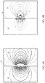
- FIG. 4A is a plot of a simulation of the electric field transmitted from an improved antenna through a metallic coating along a fore-aft side profile of the vehicle;
- FIG. 4B is a plot of a simulation of the electric field transmitted from an improved antenna through a metallic coating along a fore-aft top profile of the vehicle;
- FIG. 5A is a plot of a far field simulation of the transmission of an improved antenna through a metallic coating along a fore-aft side profile of the vehicle;
- FIG. 5B is a plot of a far field simulation of the transmission of an improved antenna through a metallic coating along a fore-aft top profile of the vehicle;
- FIG. 6A is a plot of a simulation of the electric field transmitted from a conventional antenna through a metallic coating along a fore-aft side profile of the vehicle;
- FIG. 6B is a plot of a simulation of the electric field transmitted from a conventional antenna through a metallic coating along a fore-aft top profile of the vehicle;
- FIG. 7A is a plot of a far field simulation of the transmission of a conventional antenna through a metallic coating along a fore-aft side profile of the vehicle;
- FIG. 7B is a plot of a far field simulation of the transmission of a conventional antenna through a metallic coating along a fore-aft top profile of the vehicle.
- FIG. 8 is a block diagram demonstrating a communication system in accordance with the disclosure.
- the terms “upper,” “lower,” “right,” “left,” “rear,” “front,” “vertical,” “horizontal,” and derivatives thereof shall relate to the device as oriented in FIG. 1 .
- the device may assume various alternative orientations and step sequences, except where expressly specified to the contrary.
- the specific devices and processes illustrated in the attached drawings, and described in the following specification are simply exemplary embodiments of the inventive concepts defined in the appended claims. Hence, specific dimensions and other physical characteristics relating to the embodiments disclosed herein are not to be considered as limiting, unless the claims expressly state otherwise.
- a vehicle 10 is shown approaching a toll station 12 comprising a toll reader 14 .
- the toll reader 14 may be configured to emit a first wireless signal 16 configured to activate a communication module 18 of the vehicle 10 .
- the communication module 18 may identify a proximity to the toll station 12 and communicate an identification code via a second wireless signal 20 .
- the toll reader 14 may record the identification code and apply a toll or fee to an account associated with the vehicle 10 .
- each of the wireless signals 16 and 20 may correspond to polarized radio frequency signals (e.g. horizontally or vertically polarized signals). Though the recordation and application of the toll or fee is described as being processed by the toll reader 14 , it shall be understood that these functions may similarly be processed by various systems or servers in communication with the toll reader 14 .
- the communication module 18 may comprise a communication circuit 22 (e.g. a transceiver circuit) configured to monitor for the first wireless signal 16 .
- the communication circuit 22 may comprise an antenna 24 disposed proximate to an interior surface of a windshield 26 of the vehicle 10 .
- the windshield 26 may comprise a metallic coating 28 , which may be deposited, laminated, or otherwise applied to on one or more substrates forming the windshield 26 .
- the metallic coating 28 may correspond to silver and/or metallic oxides sputtered or otherwise deposited on the transparent substrates of the windshield 26 . In this configuration, the metallic coating 28 may provide for a spectrally selective filter to control or limit solar radiation 30 from entering a passenger compartment 32 of the vehicle 10 .
- the metallic coating 28 may further be supplied with electrical current to heat and defog or defrost the windshield 26 .
- the communication circuit 22 and antenna 24 may be similarly utilized for any window comprising the metallic coating 28 .
- the metallic coating 28 may provide the benefit of limiting the solar radiation 30 entering the passenger compartment 32
- the metallic coating 28 may also attenuate or restrict the radio frequency (RF) signals (e.g. the first wireless signal 16 and the second wireless signal 20 ) from passing through the windshield 26 .
- the disclosure provides for a beneficial arrangement of the antenna 24 that limits the attenuation of the RF signals while maintaining the benefits of the metallic coating 28 .
- the disclosure provides for methods not only capable of passing the RF signals, but further improving the performance of the communication circuit 22 by utilizing the metallic coating 28 to improve or amplify the transmission of the RF signals through the windshield 26 .
- the communication module 18 may have two transmission modes. In an active mode, the communication module 18 may utilize a powered transmitter to send a signal to the toll reader 14 . Additionally, in a passive mode, the communication module 18 may utilize an impedance match or mismatch to reflect a signal received from toll reader 14 . Accordingly, the communication module 18 may be optimized to communicate with the toll reader 14 through the windshield 26 comprising the metallic coating 28 .
- the disclosure may provide for similar configurations to be utilized with various wireless communication modules.
- the communication circuit 22 and antenna 24 as discussed herein may be configured to communicate with various forms of wireless communication modules, including, but not limited to, wireless payment modules, wireless access modules, wireless security modules, and various other wireless communication devices.
- the systems provided by the disclosure may be utilized to improve the transmission of wireless signals for various applications. Such applications may include communications with payment stations, access barriers, security systems, and various other systems or devices configured to communicate wirelessly.
- the antenna 24 may be located proximate to a bottom portion 42 of the windshield 26 near a centerline 44 of the windshield 26 .
- the antenna 24 may also be located proximate an upper portion 46 of the windshield 26 proximate to the centerline 44 .
- the antenna 24 may be conductively connected to the communication circuit 22 , which may be disposed in an interior mirror assembly 48 or display mirror in connection with or disposed proximate to an interior surface 26 a of the windshield 26 . Though specific locations (e.g.
- the antenna 24 may be positioned in a variety of locations proximate the windshield 26 or any other glass portion (e.g. window, sunroof, etc.) of the vehicle 10 without departing from the spirit of the disclosure.
- the antenna 24 may correspond to a multi-element antenna array 50 .
- the antenna array 50 may comprise an active component 50 a (e.g. a source element) and a passive component 50 b (e.g. a parasitic element).
- the active component 50 a may extend substantially in a first direction 52 , which may be horizontal or parallel to an operating surface of the vehicle 10 .
- the active component 50 a may be formed by an electrical conductor 53 extending proximate to the interior surface 26 a .
- the active component 50 a or source antenna may be implemented in a variety of configurations, including, but not limited to, a dipole antenna (e.g.
- the active component 50 a may be printed on a circuit board or other substrate.
- the active component 50 a may also be formed by a wire, a metal stamping, a metal extrusion, or made up of a parallel metal plate separated by a dielectric (e.g. air, polymers, plastics, etc.) such as a ceramic patch antenna.
- a dielectric e.g. air, polymers, plastics, etc.
- the electrical conductor 53 may be any shape that results in a specific radiation emission direction/polarization.
- the improved transmission of the antenna 24 may be the result of a directional radiation pattern formed by the combination of the active component 50 a and the passive component 50 b .
- the passive component 50 b of the antenna 24 may be formed as a portion of the metallic coating 28 .
- the passive component 50 b may be formed by one or more openings in the metallic coating 28 .
- the passive component 50 b may comprise a plurality of elongated openings 54 extending longitudinally in a second direction 56 .
- the second direction 56 may be substantially perpendicular to the first direction 52 such that the elongated openings 54 formed in the metallic coating 28 are aligned substantially vertical along windshield 26 .
- the term substantially may provide for a nominal range of measurements that may effectively provide for variations in precision and design while still achieving the beneficial configurations of the elements discussed herein. Accordingly, an object that is described as being substantially perpendicular in relative orientation may vary 5 to 10 degrees without departing from the spirit of the disclosure.
- the active component 50 a is described as horizontal and the passive component 50 b is described as vertical in this particular embodiment, the active component 50 a may be vertical and the passive component 50 b may be horizontal in some embodiments. Accordingly, the disclosure may provide for the antenna 24 to be utilized for vertically or horizontally polarized signals.
- the elongated openings 54 may extend substantially parallel to each other and define a horizontal width or slot width w slot of the passive component 50 b .
- the slot width w slot of the passive component 50 b may extend from a first opening 54 a closest to a passenger-side 58 of the vehicle 10 to a second opening 54 b closest to a driver-side 60 of the vehicle 10 .
- Between the first opening 54 a and the second opening 54 b , and at least one intermediate opening 54 c may be formed in a spaced configuration.
- the intermediate opening 54 c may comprise a plurality of intermediate openings 54 c . In such embodiments, the intermediate openings may be evenly spaced between the first opening 54 a and the second opening 54 b.
- the elongated openings 54 further define a height or slot height h slot of the passive component 50 b .
- the slot height h slot may extend in a second direction 56 and intersect with the first direction 52 (e.g. the horizontal direction) of the active component 50 a .
- the active component 50 a may be positioned along a central portion 61 of the elongated openings 54 such that the slot height h slot extends on both sides of the active component 50 a .
- the active component 50 a may be positioned a spacing distance d from the interior surface 26 a of the windshield 26 . In this configuration, the passive component 50 b may receive signals uniformly along the slot height h slot .
- the elongated openings 54 may be formed in the metallic coating 28 via an ablation or removal process.
- the ablation process may utilize a laser to selectively remove the metallic coating 28 from the substrates of the windshield 26 by directing a laser beam at the metallic coating 28 .
- the laser beam may be configured to deliver a controlled amount of energy at a laser spot defined where the beam impinges a desired surface. This controlled amount of energy is selected to liquefy, vaporize, or otherwise rapidly expand the surface material (e.g. the metallic coating 28 ) at the laser spot to cause it to be removed.
- laser ablation is discussed as a process capable of providing the elongated openings 54 , various other processes may be utilized without departing from the spirit of the disclosure.
- the elongated openings 54 may be produced by masking the area of the elongated openings 54 during the coating process rather than removing the metallic coating 28 after the coating process.
- the elongated openings 54 form a rectangular surface area A or slot-like shape on the windshield 26 .
- the slot height h slot may be greater than the slot width w slot of the passive component 50 b . This configuration may be important to the operation of the passive component 50 b .
- the slot height h slot may be less than twice a wavelength of the target frequency. For example, if the target frequency of the wireless signals 16 and 20 is 910 MHz, the slot height h slot may be less than less than 692 mm (twice the target frequency's wavelength in free space).
- the slot height h slot may be less than half of the target wavelength.
- the antenna 24 may be configured to effectively transmit RF signals over a variety of frequencies.
- the antenna 24 may be configured to communicate in the MHz or GHz range (e.g. 900 MHz, 915 MHz, 2.4 GHz, 5 GHz, etc.).
- the elongated openings 54 of the passive component 50 b may correspond to narrow slots that may be ablated or otherwise formed in the metallic coating 28 .
- the elongated openings 54 may be formed in the metallic coating having an opening width less than 1 mm.
- the opening width may extend along the first direction 52 and form the elongated opening 54 along the slot height h slot .
- the opening width may be less than 0.5 mm or less than 0.2 mm. In an exemplary embodiment, the opening width may be less than 0.1 mm.
- the elongated openings 54 may be spaced apart having a spacing distance S that may range from 0.1 mm to 25 mm.
- the spacing distance S between each of the elongated openings 54 may maintain the metallic coating 28 extending from a top extent 62 to a bottom extent 64 of the passive component 50 b .
- the metallic coating 28 may extend uniformly between the elongated openings 54 over the spacing distance S such that electrical current may be conducted within the rectangular surface area A.
- a defrost capability of the metallic coating 28 may be maintained within the rectangular surface area A of the passive component 50 b .
- the metallic coating 28 may be maintained within the rectangular surface area A such that the elongated openings 54 extend over less than 20% of the rectangular surface area A. In this way, the defrost capability of the metallic coating 28 may be maintained over 80% or more of the rectangular surface area A.
- FIGS. 4A and 4B plots of a simulation of the electric field transmitted from the antenna 24 through the metallic coating 28 are shown.
- FIG. 4A demonstrates the electric field along a fore-aft side profile of the vehicle 10
- FIG. 4B demonstrates the electric field along a fore-aft top profile of the vehicle 10 .
- the passenger compartment 32 and an exterior region 72 are shown in FIGS. 4A and 4B .
- the electric field is greater in magnitude and range in the exterior region 72 outside the vehicle 10 than in the passenger compartment 32 .
- the simulation demonstrates that the interaction of the active component 50 a and the passive component 50 b of the antenna array 50 provide for improved operation of the communication circuit 22 .
- FIGS. 5A and 5B plots of a far field simulation of the transmission of the antenna 24 through the metallic coating 28 are shown.
- FIG. 5A demonstrates the far field simulation along a fore-aft side profile of the vehicle 10
- FIG. 5B demonstrates the far field simulation along a fore-aft top profile of the vehicle 10 .
- the passenger compartment 32 and an exterior region 72 are shown in FIGS. 5A and 5B .
- the far field simulation provides similar results to the electric field simulation. As shown, the far field is also greater in magnitude and range in the exterior region 72 outside the vehicle 10 than in the passenger compartment 32 .
- FIGS. 6A, 6B, 7A, and 7B plots of simulations of an electric field ( 6 A and 6 B) and a far field transmitted ( 7 A and 7 B) from a conventional antenna positioned proximate a windshield 76 with a continuous metallic coating are shown.
- the results of FIGS. 6A, 6B, 7A, and 7B are provided to demonstrate the improvements provided by the antenna array 50 of the disclosure.
- FIGS. 6A and 7A demonstrate the fields along a fore-aft side profile of a vehicle.
- FIGS. 6B and 7B demonstrate the fields along a fore-aft top profile of a vehicle. In contrast with the results shown in FIGS.
- the simulations for the conventional antenna shown in 6 A, 6 B, 7 A, and 7 B demonstrate that the transmissions are significantly and, in some cases, entirely inhibited by the metallic coating of the windshield 76 .
- the fields in each of the simulations is negligible in the exterior region 72 and fail to pass through the windshield 76 outside the vehicle. Accordingly, the results for the conventional antenna demonstrated in FIGS. 6A, 6B, 7A , and 7 B demonstrate that the interaction of the active component 50 a and the passive component 50 b of the antenna array 50 provide for improved operation of the communication circuit 22 .
- the communication module 18 may comprise a controller 82 in communication with the communication circuit 22 and the antenna 24 .
- the communication module 18 may be configured to draw power from a power supply 84 .
- the power supply 84 may correspond to a dedicated battery of the communication circuit 22 or a direct current power supply from the vehicle 10 .
- the controller 82 may be configured to control the communication circuit 22 to effectively communicate through the metallic coating 28 of the windshield 26 .
- the controller 82 may comprise a processor 86 and a memory 88 .
- the memory 88 may be configured to store one or more instructions to support the processing steps of the processor 86 in order to enable the various operations discussed herein.
- the controller 82 of the communication module 18 may further be in communication with the interior mirror assembly 48 or other devices incorporated in the vehicle 10 .
- the controller 82 may be operable to communicate via a vehicle communication bus 90 .
- the controller 82 may be operable to communicate with a number of vehicle systems (e.g. a navigation system, vehicle control module, etc.).
- the interior mirror assembly 48 may comprise a display screen 92 .
- the display screen 92 may comprise any form of video screen, for example a light emitting diode (LED) display, organic LED display, liquid crystal display (LCD), etc.
- the controller 82 may display various forms of image or video data on the display screen 92 .
- the communication module 18 may be implemented in various portions and in communication with various devices and systems of the vehicle 10 without departing from the spirit of the disclosure.
Landscapes
- Engineering & Computer Science (AREA)
- Computer Networks & Wireless Communication (AREA)
- Signal Processing (AREA)
- Remote Sensing (AREA)
- Devices For Checking Fares Or Tickets At Control Points (AREA)
- Business, Economics & Management (AREA)
- Finance (AREA)
- Physics & Mathematics (AREA)
- General Physics & Mathematics (AREA)
Abstract
Description
Claims (21)
Priority Applications (1)
| Application Number | Priority Date | Filing Date | Title |
|---|---|---|---|
| US16/164,937 US10673122B2 (en) | 2017-10-20 | 2018-10-19 | Vehicle communication module with improved transmission |
Applications Claiming Priority (2)
| Application Number | Priority Date | Filing Date | Title |
|---|---|---|---|
| US201762575052P | 2017-10-20 | 2017-10-20 | |
| US16/164,937 US10673122B2 (en) | 2017-10-20 | 2018-10-19 | Vehicle communication module with improved transmission |
Publications (2)
| Publication Number | Publication Date |
|---|---|
| US20190123421A1 US20190123421A1 (en) | 2019-04-25 |
| US10673122B2 true US10673122B2 (en) | 2020-06-02 |
Family
ID=66171206
Family Applications (1)
| Application Number | Title | Priority Date | Filing Date |
|---|---|---|---|
| US16/164,937 Active US10673122B2 (en) | 2017-10-20 | 2018-10-19 | Vehicle communication module with improved transmission |
Country Status (2)
| Country | Link |
|---|---|
| US (1) | US10673122B2 (en) |
| WO (1) | WO2019077584A1 (en) |
Cited By (1)
| Publication number | Priority date | Publication date | Assignee | Title |
|---|---|---|---|---|
| US12100904B2 (en) | 2022-08-08 | 2024-09-24 | Hyundai Motor Company | Glass antenna structure |
Families Citing this family (2)
| Publication number | Priority date | Publication date | Assignee | Title |
|---|---|---|---|---|
| CN110466323B (en) * | 2019-08-09 | 2021-10-19 | 福耀玻璃工业集团股份有限公司 | Windows and Vehicles |
| CN114843737B (en) * | 2022-03-31 | 2025-02-07 | 岚图汽车科技有限公司 | A skylight rolling glass roof structure and vehicle capable of taking into account GNSS antenna |
Citations (13)
| Publication number | Priority date | Publication date | Assignee | Title |
|---|---|---|---|---|
| US3793590A (en) * | 1972-09-01 | 1974-02-19 | Gen Motors Corp | Window mounted vehicular radio antenna |
| US5739794A (en) * | 1995-05-22 | 1998-04-14 | General Motors Corporation | Vehicle window antenna with parasitic slot transmission line |
| US5898407A (en) * | 1995-09-02 | 1999-04-27 | Flachglas Automotive Gmbh | Motor vehicle with antenna window with improved radiation and reception characteristics |
| US6275157B1 (en) * | 1999-05-27 | 2001-08-14 | Intermec Ip Corp. | Embedded RFID transponder in vehicle window glass |
| US20030164801A1 (en) * | 2002-03-04 | 2003-09-04 | Jordan David Frederick | Method of RF grounding glass mounted antennas to automotive metal frames |
| US20040119644A1 (en) * | 2000-10-26 | 2004-06-24 | Carles Puente-Baliarda | Antenna system for a motor vehicle |
| US20060139223A1 (en) * | 2004-12-29 | 2006-06-29 | Agc Automotive Americas R&D Inc. | Slot coupling patch antenna |
| US20120154229A1 (en) * | 2009-07-09 | 2012-06-21 | Asahi Glass Company, Limited | Windowpane for vehicle and antenna |
| US20140266931A1 (en) * | 2013-03-15 | 2014-09-18 | Agc Flat Glass North America, Inc. | Window assembly with transparent regions having a performance enhancing slit formed therein |
| US9007215B2 (en) * | 2006-12-21 | 2015-04-14 | Neology, Inc. | Systems and methods for a RFID enabled metal license plate |
| US20150357700A1 (en) * | 2013-02-21 | 2015-12-10 | Asahi Glass Company, Limited | Vehicle window glass and antenna |
| US20160006112A1 (en) * | 2013-03-27 | 2016-01-07 | Asahi Glass Company, Limited | Windshield and antenna |
| US20170113619A1 (en) * | 2015-10-22 | 2017-04-27 | Gentex Corporation | Integrated vehicle communication system and method |
-
2018
- 2018-10-19 US US16/164,937 patent/US10673122B2/en active Active
- 2018-10-19 WO PCT/IB2018/058170 patent/WO2019077584A1/en not_active Ceased
Patent Citations (14)
| Publication number | Priority date | Publication date | Assignee | Title |
|---|---|---|---|---|
| US3793590A (en) * | 1972-09-01 | 1974-02-19 | Gen Motors Corp | Window mounted vehicular radio antenna |
| US5739794A (en) * | 1995-05-22 | 1998-04-14 | General Motors Corporation | Vehicle window antenna with parasitic slot transmission line |
| US5898407A (en) * | 1995-09-02 | 1999-04-27 | Flachglas Automotive Gmbh | Motor vehicle with antenna window with improved radiation and reception characteristics |
| US6275157B1 (en) * | 1999-05-27 | 2001-08-14 | Intermec Ip Corp. | Embedded RFID transponder in vehicle window glass |
| US20040119644A1 (en) * | 2000-10-26 | 2004-06-24 | Carles Puente-Baliarda | Antenna system for a motor vehicle |
| US20030164801A1 (en) * | 2002-03-04 | 2003-09-04 | Jordan David Frederick | Method of RF grounding glass mounted antennas to automotive metal frames |
| US20060139223A1 (en) * | 2004-12-29 | 2006-06-29 | Agc Automotive Americas R&D Inc. | Slot coupling patch antenna |
| US9007215B2 (en) * | 2006-12-21 | 2015-04-14 | Neology, Inc. | Systems and methods for a RFID enabled metal license plate |
| US20120154229A1 (en) * | 2009-07-09 | 2012-06-21 | Asahi Glass Company, Limited | Windowpane for vehicle and antenna |
| US20150357700A1 (en) * | 2013-02-21 | 2015-12-10 | Asahi Glass Company, Limited | Vehicle window glass and antenna |
| US20140266931A1 (en) * | 2013-03-15 | 2014-09-18 | Agc Flat Glass North America, Inc. | Window assembly with transparent regions having a performance enhancing slit formed therein |
| US20160013539A1 (en) * | 2013-03-15 | 2016-01-14 | Agc Automotive Americas R& D, Inc. | Window Assembly With Transparent Regions having A Performance Enhancing Slit Formed Therein |
| US20160006112A1 (en) * | 2013-03-27 | 2016-01-07 | Asahi Glass Company, Limited | Windshield and antenna |
| US20170113619A1 (en) * | 2015-10-22 | 2017-04-27 | Gentex Corporation | Integrated vehicle communication system and method |
Cited By (1)
| Publication number | Priority date | Publication date | Assignee | Title |
|---|---|---|---|---|
| US12100904B2 (en) | 2022-08-08 | 2024-09-24 | Hyundai Motor Company | Glass antenna structure |
Also Published As
| Publication number | Publication date |
|---|---|
| WO2019077584A1 (en) | 2019-04-25 |
| US20190123421A1 (en) | 2019-04-25 |
Similar Documents
| Publication | Publication Date | Title |
|---|---|---|
| US20240178555A1 (en) | Smart antenna for in-vehicle applications that can be integrated with tcu and other electronics | |
| US11456525B2 (en) | Antenna module and vehicle | |
| US11069961B2 (en) | Antenna device having an antenna element coupled at a notch of a ground conductor thereof | |
| US10673122B2 (en) | Vehicle communication module with improved transmission | |
| US7501992B2 (en) | Planar antenna | |
| US8866681B2 (en) | Vehicle mirror antenna assembly | |
| US20250266605A1 (en) | Antenna module disposed in vehicle | |
| JP7279495B2 (en) | Vehicle communication device | |
| KR102536245B1 (en) | Radome, radar sensor for vehicle and sensing apparatus for vehicle having the same | |
| KR102725690B1 (en) | Antenna module placed on a vehicle | |
| US10290932B2 (en) | Glass antenna and vehicle window glass provided with glass antenna | |
| KR102931618B1 (en) | Antenna module disposed in vehicle | |
| JP7688655B2 (en) | Vehicle Antenna System | |
| KR20240144238A (en) | Wideband antennas placed on vehicles | |
| JP7643450B2 (en) | Vehicle Antenna System | |
| KR102346201B1 (en) | Radar module and automotive radar apparatus having the same | |
| KR102707823B1 (en) | Antenna module placed on a vehicle | |
| EP4554001A1 (en) | Antenna module arranged in vehicle | |
| US12573769B2 (en) | Antenna device | |
| KR102927006B1 (en) | Wideband antennas deployed on vehicles | |
| KR20240095251A (en) | Antenna module placed in vehicle | |
| KR102719434B1 (en) | Antenna module placed on a vehicle | |
| KR102924530B1 (en) | Wideband antennas deployed on vehicles | |
| US12119571B2 (en) | Antenna device | |
| KR20250110139A (en) | Antenna module placed on a vehicle |
Legal Events
| Date | Code | Title | Description |
|---|---|---|---|
| AS | Assignment |
Owner name: GENTEX CORPORATION, MICHIGAN Free format text: ASSIGNMENT OF ASSIGNORS INTEREST;ASSIGNORS:APPOLD, BENJAMIN P.;PAPAY, DOUGLAS C.;REEL/FRAME:047232/0452 Effective date: 20181018 |
|
| FEPP | Fee payment procedure |
Free format text: ENTITY STATUS SET TO UNDISCOUNTED (ORIGINAL EVENT CODE: BIG.); ENTITY STATUS OF PATENT OWNER: LARGE ENTITY |
|
| STPP | Information on status: patent application and granting procedure in general |
Free format text: DOCKETED NEW CASE - READY FOR EXAMINATION |
|
| STPP | Information on status: patent application and granting procedure in general |
Free format text: NON FINAL ACTION MAILED |
|
| STPP | Information on status: patent application and granting procedure in general |
Free format text: RESPONSE TO NON-FINAL OFFICE ACTION ENTERED AND FORWARDED TO EXAMINER |
|
| STPP | Information on status: patent application and granting procedure in general |
Free format text: FINAL REJECTION MAILED |
|
| STPP | Information on status: patent application and granting procedure in general |
Free format text: DOCKETED NEW CASE - READY FOR EXAMINATION |
|
| STPP | Information on status: patent application and granting procedure in general |
Free format text: NOTICE OF ALLOWANCE MAILED -- APPLICATION RECEIVED IN OFFICE OF PUBLICATIONS |
|
| STPP | Information on status: patent application and granting procedure in general |
Free format text: PUBLICATIONS -- ISSUE FEE PAYMENT VERIFIED |
|
| STCF | Information on status: patent grant |
Free format text: PATENTED CASE |
|
| MAFP | Maintenance fee payment |
Free format text: PAYMENT OF MAINTENANCE FEE, 4TH YEAR, LARGE ENTITY (ORIGINAL EVENT CODE: M1551); ENTITY STATUS OF PATENT OWNER: LARGE ENTITY Year of fee payment: 4 |