US10671826B2 - Indoor location services using a distributed lighting network - Google Patents
Indoor location services using a distributed lighting network Download PDFInfo
- Publication number
- US10671826B2 US10671826B2 US15/832,341 US201715832341A US10671826B2 US 10671826 B2 US10671826 B2 US 10671826B2 US 201715832341 A US201715832341 A US 201715832341A US 10671826 B2 US10671826 B2 US 10671826B2
- Authority
- US
- United States
- Prior art keywords
- lighting fixtures
- lighting
- devices
- mobile device
- network
- Prior art date
- Legal status (The legal status is an assumption and is not a legal conclusion. Google has not performed a legal analysis and makes no representation as to the accuracy of the status listed.)
- Active
Links
Images


Classifications
-
- G06K9/00—
-
- G—PHYSICS
- G01—MEASURING; TESTING
- G01C—MEASURING DISTANCES, LEVELS OR BEARINGS; SURVEYING; NAVIGATION; GYROSCOPIC INSTRUMENTS; PHOTOGRAMMETRY OR VIDEOGRAMMETRY
- G01C21/00—Navigation; Navigational instruments not provided for in groups G01C1/00 - G01C19/00
- G01C21/20—Instruments for performing navigational calculations
- G01C21/206—Instruments for performing navigational calculations specially adapted for indoor navigation
-
- G—PHYSICS
- G01—MEASURING; TESTING
- G01S—RADIO DIRECTION-FINDING; RADIO NAVIGATION; DETERMINING DISTANCE OR VELOCITY BY USE OF RADIO WAVES; LOCATING OR PRESENCE-DETECTING BY USE OF THE REFLECTION OR RERADIATION OF RADIO WAVES; ANALOGOUS ARRANGEMENTS USING OTHER WAVES
- G01S13/00—Systems using the reflection or reradiation of radio waves, e.g. radar systems; Analogous systems using reflection or reradiation of waves whose nature or wavelength is irrelevant or unspecified
- G01S13/74—Systems using reradiation of radio waves, e.g. secondary radar systems; Analogous systems
- G01S13/82—Systems using reradiation of radio waves, e.g. secondary radar systems; Analogous systems wherein continuous-type signals are transmitted
- G01S13/84—Systems using reradiation of radio waves, e.g. secondary radar systems; Analogous systems wherein continuous-type signals are transmitted for distance determination by phase measurement
-
- G—PHYSICS
- G06—COMPUTING OR CALCULATING; COUNTING
- G06F—ELECTRIC DIGITAL DATA PROCESSING
- G06F3/00—Input arrangements for transferring data to be processed into a form capable of being handled by the computer; Output arrangements for transferring data from processing unit to output unit, e.g. interface arrangements
- G06F3/01—Input arrangements or combined input and output arrangements for interaction between user and computer
- G06F3/048—Interaction techniques based on graphical user interfaces [GUI]
-
- G06K9/00771—
-
- G—PHYSICS
- G06—COMPUTING OR CALCULATING; COUNTING
- G06T—IMAGE DATA PROCESSING OR GENERATION, IN GENERAL
- G06T5/00—Image enhancement or restoration
- G06T5/50—Image enhancement or restoration using two or more images, e.g. averaging or subtraction
-
- G—PHYSICS
- G06—COMPUTING OR CALCULATING; COUNTING
- G06V—IMAGE OR VIDEO RECOGNITION OR UNDERSTANDING
- G06V20/00—Scenes; Scene-specific elements
- G06V20/50—Context or environment of the image
- G06V20/52—Surveillance or monitoring of activities, e.g. for recognising suspicious objects
-
- H02J13/0062—
-
- H02J13/0079—
-
- H02J13/1321—
-
- H02J13/1331—
-
- H02J13/1337—
-
- H—ELECTRICITY
- H04—ELECTRIC COMMUNICATION TECHNIQUE
- H04L—TRANSMISSION OF DIGITAL INFORMATION, e.g. TELEGRAPHIC COMMUNICATION
- H04L12/00—Data switching networks
- H04L12/28—Data switching networks characterised by path configuration, e.g. LAN [Local Area Networks] or WAN [Wide Area Networks]
- H04L12/2803—Home automation networks
- H04L12/2807—Exchanging configuration information on appliance services in a home automation network
- H04L12/2809—Exchanging configuration information on appliance services in a home automation network indicating that an appliance service is present in a home automation network
-
- H—ELECTRICITY
- H04—ELECTRIC COMMUNICATION TECHNIQUE
- H04L—TRANSMISSION OF DIGITAL INFORMATION, e.g. TELEGRAPHIC COMMUNICATION
- H04L67/00—Network arrangements or protocols for supporting network services or applications
- H04L67/01—Protocols
- H04L67/12—Protocols specially adapted for proprietary or special-purpose networking environments, e.g. medical networks, sensor networks, networks in vehicles or remote metering networks
-
- H—ELECTRICITY
- H04—ELECTRIC COMMUNICATION TECHNIQUE
- H04W—WIRELESS COMMUNICATION NETWORKS
- H04W4/00—Services specially adapted for wireless communication networks; Facilities therefor
- H04W4/02—Services making use of location information
- H04W4/023—Services making use of location information using mutual or relative location information between multiple location based services [LBS] targets or of distance thresholds
-
- H—ELECTRICITY
- H04—ELECTRIC COMMUNICATION TECHNIQUE
- H04W—WIRELESS COMMUNICATION NETWORKS
- H04W4/00—Services specially adapted for wireless communication networks; Facilities therefor
- H04W4/02—Services making use of location information
- H04W4/025—Services making use of location information using location based information parameters
-
- H—ELECTRICITY
- H04—ELECTRIC COMMUNICATION TECHNIQUE
- H04W—WIRELESS COMMUNICATION NETWORKS
- H04W4/00—Services specially adapted for wireless communication networks; Facilities therefor
- H04W4/30—Services specially adapted for particular environments, situations or purposes
- H04W4/33—Services specially adapted for particular environments, situations or purposes for indoor environments, e.g. buildings
-
- H—ELECTRICITY
- H05—ELECTRIC TECHNIQUES NOT OTHERWISE PROVIDED FOR
- H05B—ELECTRIC HEATING; ELECTRIC LIGHT SOURCES NOT OTHERWISE PROVIDED FOR; CIRCUIT ARRANGEMENTS FOR ELECTRIC LIGHT SOURCES, IN GENERAL
- H05B45/00—Circuit arrangements for operating light-emitting diodes [LED]
- H05B45/10—Controlling the intensity of the light
-
- G—PHYSICS
- G06—COMPUTING OR CALCULATING; COUNTING
- G06T—IMAGE DATA PROCESSING OR GENERATION, IN GENERAL
- G06T2207/00—Indexing scheme for image analysis or image enhancement
- G06T2207/20—Special algorithmic details
- G06T2207/20212—Image combination
- G06T2207/20216—Image averaging
-
- H02J2107/40—
-
- H—ELECTRICITY
- H05—ELECTRIC TECHNIQUES NOT OTHERWISE PROVIDED FOR
- H05B—ELECTRIC HEATING; ELECTRIC LIGHT SOURCES NOT OTHERWISE PROVIDED FOR; CIRCUIT ARRANGEMENTS FOR ELECTRIC LIGHT SOURCES, IN GENERAL
- H05B47/00—Circuit arrangements for operating light sources in general, i.e. where the type of light source is not relevant
- H05B47/10—Controlling the light source
- H05B47/175—Controlling the light source by remote control
- H05B47/198—Grouping of control procedures or address assignation to light sources
- H05B47/199—Commissioning of light sources
-
- Y—GENERAL TAGGING OF NEW TECHNOLOGICAL DEVELOPMENTS; GENERAL TAGGING OF CROSS-SECTIONAL TECHNOLOGIES SPANNING OVER SEVERAL SECTIONS OF THE IPC; TECHNICAL SUBJECTS COVERED BY FORMER USPC CROSS-REFERENCE ART COLLECTIONS [XRACs] AND DIGESTS
- Y02—TECHNOLOGIES OR APPLICATIONS FOR MITIGATION OR ADAPTATION AGAINST CLIMATE CHANGE
- Y02B—CLIMATE CHANGE MITIGATION TECHNOLOGIES RELATED TO BUILDINGS, e.g. HOUSING, HOUSE APPLIANCES OR RELATED END-USER APPLICATIONS
- Y02B70/00—Technologies for an efficient end-user side electric power management and consumption
- Y02B70/30—Systems integrating technologies related to power network operation and communication or information technologies for improving the carbon footprint of the management of residential or tertiary loads, i.e. smart grids as climate change mitigation technology in the buildings sector, including also the last stages of power distribution and the control, monitoring or operating management systems at local level
-
- Y02B70/325—
-
- Y02B70/3283—
-
- Y—GENERAL TAGGING OF NEW TECHNOLOGICAL DEVELOPMENTS; GENERAL TAGGING OF CROSS-SECTIONAL TECHNOLOGIES SPANNING OVER SEVERAL SECTIONS OF THE IPC; TECHNICAL SUBJECTS COVERED BY FORMER USPC CROSS-REFERENCE ART COLLECTIONS [XRACs] AND DIGESTS
- Y02—TECHNOLOGIES OR APPLICATIONS FOR MITIGATION OR ADAPTATION AGAINST CLIMATE CHANGE
- Y02B—CLIMATE CHANGE MITIGATION TECHNOLOGIES RELATED TO BUILDINGS, e.g. HOUSING, HOUSE APPLIANCES OR RELATED END-USER APPLICATIONS
- Y02B90/00—Enabling technologies or technologies with a potential or indirect contribution to GHG emissions mitigation
- Y02B90/20—Smart grids as enabling technology in buildings sector
-
- Y02B90/2638—
-
- Y04S20/228—
-
- Y—GENERAL TAGGING OF NEW TECHNOLOGICAL DEVELOPMENTS; GENERAL TAGGING OF CROSS-SECTIONAL TECHNOLOGIES SPANNING OVER SEVERAL SECTIONS OF THE IPC; TECHNICAL SUBJECTS COVERED BY FORMER USPC CROSS-REFERENCE ART COLLECTIONS [XRACs] AND DIGESTS
- Y04—INFORMATION OR COMMUNICATION TECHNOLOGIES HAVING AN IMPACT ON OTHER TECHNOLOGY AREAS
- Y04S—SYSTEMS INTEGRATING TECHNOLOGIES RELATED TO POWER NETWORK OPERATION, COMMUNICATION OR INFORMATION TECHNOLOGIES FOR IMPROVING THE ELECTRICAL POWER GENERATION, TRANSMISSION, DISTRIBUTION, MANAGEMENT OR USAGE, i.e. SMART GRIDS
- Y04S20/00—Management or operation of end-user stationary applications or the last stages of power distribution; Controlling, monitoring or operating thereof
- Y04S20/20—End-user application control systems
- Y04S20/242—Home appliances
- Y04S20/246—Home appliances the system involving the remote operation of lamps or lighting equipment
-
- Y—GENERAL TAGGING OF NEW TECHNOLOGICAL DEVELOPMENTS; GENERAL TAGGING OF CROSS-SECTIONAL TECHNOLOGIES SPANNING OVER SEVERAL SECTIONS OF THE IPC; TECHNICAL SUBJECTS COVERED BY FORMER USPC CROSS-REFERENCE ART COLLECTIONS [XRACs] AND DIGESTS
- Y04—INFORMATION OR COMMUNICATION TECHNOLOGIES HAVING AN IMPACT ON OTHER TECHNOLOGY AREAS
- Y04S—SYSTEMS INTEGRATING TECHNOLOGIES RELATED TO POWER NETWORK OPERATION, COMMUNICATION OR INFORMATION TECHNOLOGIES FOR IMPROVING THE ELECTRICAL POWER GENERATION, TRANSMISSION, DISTRIBUTION, MANAGEMENT OR USAGE, i.e. SMART GRIDS
- Y04S40/00—Systems for electrical power generation, transmission, distribution or end-user application management characterised by the use of communication or information technologies, or communication or information technology specific aspects supporting them
- Y04S40/12—Systems for electrical power generation, transmission, distribution or end-user application management characterised by the use of communication or information technologies, or communication or information technology specific aspects supporting them characterised by data transport means between the monitoring, controlling or managing units and monitored, controlled or operated electrical equipment
- Y04S40/124—Systems for electrical power generation, transmission, distribution or end-user application management characterised by the use of communication or information technologies, or communication or information technology specific aspects supporting them characterised by data transport means between the monitoring, controlling or managing units and monitored, controlled or operated electrical equipment using wired telecommunication networks or data transmission busses
-
- Y—GENERAL TAGGING OF NEW TECHNOLOGICAL DEVELOPMENTS; GENERAL TAGGING OF CROSS-SECTIONAL TECHNOLOGIES SPANNING OVER SEVERAL SECTIONS OF THE IPC; TECHNICAL SUBJECTS COVERED BY FORMER USPC CROSS-REFERENCE ART COLLECTIONS [XRACs] AND DIGESTS
- Y04—INFORMATION OR COMMUNICATION TECHNOLOGIES HAVING AN IMPACT ON OTHER TECHNOLOGY AREAS
- Y04S—SYSTEMS INTEGRATING TECHNOLOGIES RELATED TO POWER NETWORK OPERATION, COMMUNICATION OR INFORMATION TECHNOLOGIES FOR IMPROVING THE ELECTRICAL POWER GENERATION, TRANSMISSION, DISTRIBUTION, MANAGEMENT OR USAGE, i.e. SMART GRIDS
- Y04S40/00—Systems for electrical power generation, transmission, distribution or end-user application management characterised by the use of communication or information technologies, or communication or information technology specific aspects supporting them
- Y04S40/12—Systems for electrical power generation, transmission, distribution or end-user application management characterised by the use of communication or information technologies, or communication or information technology specific aspects supporting them characterised by data transport means between the monitoring, controlling or managing units and monitored, controlled or operated electrical equipment
- Y04S40/126—Systems for electrical power generation, transmission, distribution or end-user application management characterised by the use of communication or information technologies, or communication or information technology specific aspects supporting them characterised by data transport means between the monitoring, controlling or managing units and monitored, controlled or operated electrical equipment using wireless data transmission
Definitions
- the present disclosure relates to the automatic mapping of devices in a distributed lighting network and the utilization of mapped devices in a distributed lighting network to provide indoor location services to a user.
- Lighting fixtures continue to evolve, incorporating features such as sensors, processing circuitry, networking circuitry, and the like. Accordingly, lighting fixtures may implement lighting programs, respond to the surrounding environment, and be controlled, for example, over a local area network and/or the Internet.
- lighting fixtures have been primarily concerned with measuring environmental factors directly related to the light output thereof (e.g., ambient light and occupancy). These environmental factors have generally been used to make decisions locally, for example, regarding the light output level of the lighting fixture to which the sensors are attached.
- Networking circuitry has been incorporated into many lighting fixtures to allow them to communicate with one another.
- a common approach is to form a mesh network of lighting fixtures in which the lighting fixtures can communicate with one another and/or receive commands from remote devices.
- these lighting fixture networks are used to provide control commands to various lighting fixtures or groups of lighting fixtures to adjust the light output thereof in some manner.
- a distributed lighting network includes a number of lighting fixtures and an indoor location services module.
- Each of the lighting fixtures has a known location in an indoor space, and provides a wireless beacon signal, where the wireless beacon signal identifies the lighting fixture from which it is provided and indicates a distance between a receiver of the wireless beacon signal and the lighting fixture form which the signal was provided.
- the indoor location services module determines a location of a mobile device in the indoor space based on information about each wireless beacon signal received by the mobile device and the known location of the lighting fixtures. Using the lighting fixtures to provide the wireless beacon signals, each of which has a fixed, known location, allows for highly accurate indoor location services for the mobile device.
- the location of each one of the lighting fixtures in the distributed lighting network is automatically determined by obtaining a first set of distance measurements and a second set of distance measurements and processing the first set of distance measurements and the second set of distance measurements to assign coordinates to each one of the lighting fixtures.
- the first set of distance measurements are obtained using a first measurement method.
- the second set of distance measurements is obtained using a second measurement method, which is different from the first measurement method.
- FIG. 1 is a block diagram of a distributed lighting network according to one embodiment of the present disclosure.
- FIG. 2 is a functional schematic of a lighting fixture according to one embodiment of the present disclosure.
- FIG. 3 is a functional schematic of a sensor module according to one embodiment of the present disclosure.
- FIG. 4 is a functional schematic of a lighting fixture connected to a sensor module according to one embodiment of the present disclosure.
- FIG. 5 is a functional schematic of a controller according to one embodiment of the present disclosure.
- FIG. 6 is a functional schematic of a controller connected to a sensor module according to one embodiment of the present disclosure.
- FIG. 7 is a functional schematic of a border router according to one embodiment of the present disclosure.
- FIG. 8 is a functional schematic of a border router connected to a sensor module according to one embodiment of the present disclosure.
- FIG. 9 is a diagram illustrating a distributed lighting system according to one embodiment of the present disclosure.
- FIG. 10 is a call flow diagram illustrating a process for automatically grouping a number of devices in a distributed lighting network according to one embodiment of the present disclosure.
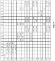
- FIG. 11 is a table indicating a detected link strength between lighting fixtures in a distributed lighting network.
- FIG. 12 is a table indicating a neighbor ranking for each one of a number of lighting fixtures in a distributed lighting network.
- FIG. 13 is a flow diagram illustrating a process for adding devices to a distributed lighting network according to one embodiment of the present disclosure.
- FIG. 14 is a diagram illustrating a distributed lighting system according to one embodiment of the present disclosure.
- FIG. 15 is a flow diagram illustrating a process for grouping devices in a distributed lighting network according to one embodiment of the present disclosure.
- FIGS. 16A through 16C are diagrams illustrating a distributed lighting network according to various embodiment of the present disclosure.
- FIG. 17 is a call flow diagram illustrating a process for adjusting the light output of one or more lighting fixtures in a distributed lighting network according to one embodiment of the present disclosure.
- FIGS. 18A through 18D are diagrams illustrating a distributed lighting network according to various embodiments of the present disclosure.
- FIG. 19 is a flow diagram illustrating a process for detecting devices near entrances and/or exits according to one embodiment of the present disclosure.
- FIG. 20 is a flow diagram illustrating a process for determining and indicating a desired position of a border router in a distributed lighting network according to one embodiment of the present disclosure.
- FIG. 21 is a flow diagram illustrating a process for calibrating one or more ambient light sensors according to one embodiment of the present disclosure.
- FIG. 22 is a call flow diagram illustrating a process for determining and using an optimal communication channel in a distributed lighting network according to one embodiment of the present disclosure.
- FIG. 23 is a call flow diagram illustrating a process for determining and using an optimal communication channel in a distributed lighting network according to one embodiment of the present disclosure.
- FIGS. 24A and 24B are flow diagrams illustrating a process for detecting occupancy using an image sensor according to one embodiment of the present disclosure.
- FIG. 25 is a flow diagram illustrating a process for adjusting a light level of a lighting fixture in order to properly detect occupancy in a lighting fixture according to one embodiment of the present disclosure.
- FIG. 26 is a functional schematic of power converter circuitry according to one embodiment of the present disclosure.
- FIG. 27 is a flow diagram illustrating a process for detecting and responding to a commissioning tool using an image sensor according to one embodiment of the present disclosure.
- FIG. 28 is a flow diagram illustrating a process for providing merged images from multiple image sensors in a distributed lighting network according to one embodiment of the present disclosure.
- FIG. 29 is a flow diagram illustrating a process for correlating image data and geospatial data and displaying the result according to one embodiment of the present disclosure.
- FIG. 30 is a flow diagram illustrating a process for mapping and registering devices in a distributed lighting network according to one embodiment of the present disclosure.
- FIG. 31 is a diagram illustrating the process described in FIG. 30 according to one embodiment of the present disclosure.
- FIG. 32 is a diagram illustrating a lighting network communications module for use with a mobile device according to one embodiment of the present disclosure.
- FIG. 33 illustrates an exemplary user interface for registering devices in a distributed lighting network according to one embodiment of the present disclosure.
- FIG. 34 is a flow diagram illustrating a process for mapping and registering devices in a distributed lighting network according to one embodiment of the present disclosure.
- FIG. 35 is a diagram illustrating the process described in FIG. 34 according to one embodiment of the present disclosure.
- FIG. 36 is a flow diagram illustrating details of the process described in FIG. 34 according to one embodiment of the present disclosure.
- FIG. 37 is a flow diagram illustrating details of the process described in FIG. 34 according to one embodiment of the present disclosure.
- FIG. 38 is a flow diagram illustrating a process for adjusting a drive signal to a light source in order to reduce the energy consumption of a lighting fixture according to one embodiment of the present disclosure.
- FIG. 39 is a diagram illustrating a process for adjusting a drive signal to a light source in order to reduce the energy consumption of a lighting fixture according to one embodiment of the present disclosure.
- FIG. 40 is a flow diagram illustrating a process for measuring and determining the power consumption of a device in a distributed lighting network according to one embodiment of the present disclosure.
- FIG. 41 is a flow diagram illustrating a process for reducing the power consumption of a device in a distributed lighting network according to one embodiment of the present disclosure.
- FIGS. 42A and 42B illustrate a lighting fixture according to one embodiment of the present disclosure.
- FIG. 43 is a functional schematic of a lighting fixture according to one embodiment of the present disclosure.
- FIG. 44 is a functional schematic of a lighting fixture connected to a sensor module according to one embodiment of the present disclosure.
- FIG. 45 illustrates a lighting fixture according to one embodiment of the present disclosure.
- FIG. 46 is a flow diagram illustrating a process for detecting an optical indicator and adjusting settings based on the optical indicator according to one embodiment of the present disclosure.
- FIG. 47 is a flow diagram illustrating a process for determining one or more environmental conditions based on sensor data measured by devices in a distributed lighting network according to one embodiment of the present disclosure.
- FIG. 48 is a flow diagram illustrating a process for adjusting one or more building management system (BMS) parameters based on sensor data measured by devices in a distributed lighting network according to one embodiment of the present disclosure.
- BMS building management system
- FIG. 49 is a call flow diagram illustrating a process for communication between devices in a distributed lighting network according to one embodiment of the present disclosure.
- FIG. 50 is a call flow diagram illustrating a process for communication between a remote device and the devices in a distributed lighting network according to one embodiment of the present disclosure.
- FIG. 51 is a flow diagram illustrating a process for transferring settings between devices in a distributed lighting network according to one embodiment of the present disclosure.
- FIGS. 52A and 52B illustrate a lighting fixture according to one embodiment of the present disclosure.
- FIG. 53 is a flow diagram illustrating a process for determining a location of each lighting fixture in a distributed lighting network according to one embodiment of the present disclosure.
- FIGS. 54A and 54B illustrate details of the process for determining the location of each lighting fixture in the distributed lighting network according to one embodiment of the present disclosure.
- FIG. 55 illustrates a process for scaling and translating relative coordinates of lighting fixtures into a real coordinate system according to one embodiment of the present disclosure.
- FIG. 56 is a flow diagram illustrating a process for generating a map of an indoor space from information collected by lighting fixtures in a distributed network according to one embodiment of the present disclosure.
- FIG. 57 illustrates providing indoor location services from one or more lighting fixtures in a distributed lighting network to a mobile device according to one embodiment of the present disclosure.
- FIG. 58 is a flow diagram illustrating a process for providing indoor location services to a mobile device in a distributed lighting network according to one embodiment of the present disclosure.
- FIG. 59 is a call flow diagram illustrating a process for providing indoor location services to a mobile device in a distributed lighting network according to one embodiment of the present disclosure.
- FIG. 60 illustrates providing indoor location services from one or more lighting fixtures in a distributed lighting network to a mobile device according to one embodiment of the present disclosure.
- FIG. 61 is a flow diagram illustrating a process for providing indoor location services to a mobile device in a distributed lighting network according to one embodiment of the present disclosure.
- FIG. 62 is a call flow diagram illustrating a process for providing indoor location services to a mobile device in a distributed lighting network according to one embodiment of the present disclosure.
- FIG. 1 illustrates a distributed lighting network 10 according to one embodiment of the present disclosure.
- the distributed lighting network 10 includes a number of lighting networks 12 , and in particular a wireless lighting network 12 A and a wired lighting network 12 B.
- the wireless lighting network 12 A includes a number of devices 14 , which may be lighting fixtures 14 A, sensor modules 14 B, controllers 14 C, and border routers 14 D.
- the devices 14 communicate with one another via wireless signals.
- the devices 14 form a wireless mesh network, such that communication between two endpoints may be accomplished via one or more hops.
- the devices 14 may communicate with one another via Institute of Electrical and Electronics Engineers (IEEE) standard 802.15 or some variant thereof.
- IEEE Institute of Electrical and Electronics Engineers
- Using a wireless mesh network to communicate among the devices 14 may increase the reliability thereof and allow the wireless lighting network 12 A to span large areas.
- the wired lighting network 12 B also includes a number of devices 14 .
- the wired lighting network 12 B may also include one or more switches 14 E.
- the devices 14 in the wired lighting network 12 B communicate with one another via signals sent over a wired interface.
- the devices 14 may communicate with one another via an Ethernet interface, which is facilitated by a switch 14 E.
- the switches 14 E are Power over Ethernet (PoE) switches such as those conforming to IEEE standard 802.3.
- PoE Power over Ethernet
- the switches 14 E may provide power to the devices 14 while simultaneously facilitating the exchange of data between the devices 14 . While each one of the devices 14 are shown individually connected to a switch 14 E, the devices 14 may be connected to one another in any manner, such that one of the devices 14 connects to one or more of the switches 14 E via one or more other devices 14 .
- Each border router 14 D may be in communication with each other border router 14 D, or a subset of each other border router 14 D. Such communication may occur in a wired or wireless manner.
- each switch 14 E may be in communication with each other switch 14 E, or a subset of each other switch 14 E. At least one of the switches 14 E is in communication with at least one of the border routers 14 D.
- the one or more border routers 14 D in communication with the one or more switches 14 E act as a bridge between the wireless lighting network 12 A and the wired lighting network 12 B, and therefore allow the separate networks to communicate with one another. Such bridge functionality may involve network address translation, network protocol translation, and the like, which is facilitated by the border router 14 D. While the border router 14 D in FIG.
- the border router 14 D may also bridge two or more separate wireless lighting networks 12 A, two or more wired lighting networks 12 B, or any combination thereof.
- multiple border routers 14 D are shown in FIG. 1 , only a single border router 14 D may be provided in some embodiments. Generally, additional border routers 14 D are provided to increase network reliability and speed.
- switches 14 E are shown in FIG. 1 , only one switch 14 E may be provided in some embodiments. Generally, additional switches 14 E are provided to support a larger number of devices 14 , since the capacity of each switch 14 E is limited.
- the functionality of the border router 14 D and the switch 14 E is combined, such that each device 14 in the wired lighting network 12 B connects directly or indirectly to one of the border routers 14 D (rather than connecting to one of the border routers 14 D via a switch 14 E).
- one or more of the border routers 14 D may also connect to other communications networks such as the Internet. Further, one or more of the border routers 14 D may interface, either directly or indirectly, with one or more remote devices 16 (e.g., a computer or wireless communications device). When communicating directly with the one or more border routers 14 D, the one or more remote devices 16 may do so in a wired or wireless fashion, and in any number of communications standards/protocols. When communicating indirectly with the one or more border routers 14 D, the one or more remote devices 16 may do so via an access point 18 connected to the Internet, which is in turn connected to the one or more border routers 14 D. Once again, the one or more border routers 14 D are responsible for translating the various network addresses, protocols, and the like between the different devices.
- the one or more border routers 14 D are responsible for translating the various network addresses, protocols, and the like between the different devices.
- one or more of the border routers 14 D may also communicate with a building management system 20 , such as those conventionally used to control HVAC, security, and other building systems. Accordingly, one or more of the border routers 14 D may include specialty communications circuitry for communicating with the building management system 20 in a wired or wireless manner. In another embodiment, the building management system 20 is fitted with a communication module (not shown) which enables wired or wireless communications with one or more of the border routers 14 D. Allowing one or more of the border routers 14 D to communicate with the building management system 20 may add significant intelligence to an existing building management system 20 , and may allow for detailed insights regarding a space as well as energy and cost savings as discussed below.
- the wireless and wired communications in the distributed lighting network 10 may occur in any number of communications standards/protocols. Additionally, the number of devices 14 , border routers 14 D, switches 14 E, remote devices 16 , and the like may be different in various embodiments. Using one or more of the border routers 14 D to bridge the wireless lighting network 12 A and the wired lighting network 12 B extends the reach of the distributed lighting network 10 , which may increase the functionality thereof. Further, using one or more of the border routers 14 D to provide a bridge to other networks and devices may significantly increase the functionality thereof as discussed below.
- the devices 14 may use the distributed lighting network 10 to communicate with one another. For example, the devices 14 may exchange status information, sensor data, commands, and the like. Messages passed between the devices 14 may be individually addressed such that the messages are received by a single one of the devices 14 , broadcast to a subset of the devices 14 , or broadcast to all of the devices 14 .
- the border routers 14 D and/or switches 14 E may collect and store information from the devices 14 . For example, the border routers 14 D may collect and store status information, sensor data, or the like from the devices 14 .
- the border routers 14 D and/or switches 14 E may relay commands from the remote devices 16 to one or more of the devices 14 , and may facilitate the collection of data from the devices 14 by the remote devices 16 , either by providing cached data located in local storage in the border routers 14 D or by requesting the data directly from the devices 14 .
- At least one border router 14 D or a designated device in communication with at least one border router 14 D may provide an Application Program Interface (API), which is made available to devices connected to the distributed lighting network 10 .
- API Application Program Interface
- relevant information regarding the functioning of each one of the devices 14 e.g., status information, sensor data, and the like
- Each one of the devices 14 may also periodically broadcast relevant operational information, which is received and stored by one or more of the border routers 14 D.
- operational information regarding each one of the devices 14 is not cached, but real time operational information can be obtained when requested.
- Virtually endless configurations exist for the storage and retrieval of information among the various components of the distributed lighting network 10 , all of which are contemplated herein.
- each one of the devices 14 is capable of operating independently of the others, and thus does not need to connect to the distributed lighting network 10 to function.
- each one of the devices 14 may be capable of detecting the occurrence of an occupancy event and responding thereto (by adjusting the light output thereof in the case of a lighting fixture 14 A), detecting changes in an ambient light level of the space surrounding the device and responding thereto (by adjusting the light output thereof in the case of a lighting fixture 14 A).
- the control logic for each one of the devices 14 is locally stored and executed, and does not require external input.
- each one of the devices 14 may consider information provided via the distributed lighting network 10 , and therefore the behavior of each one of the devices 14 may be influenced by other devices 14 in the network and/or one or more of the remote devices 16 . For example, upon detection of an occupancy event by one of the devices 14 , other devices 14 may respond to the detected occupancy event.
- a group of devices 14 may function together (e.g., sharing information and communicating with one another) without connecting to a border router 14 D.
- the border router(s) 14 D do not directly facilitate communication between the devices 14 . This is due to the local control of each device discussed above. Accordingly, a border router 14 D may or may not be provided, or may become disconnected or otherwise non-operational without causing a failure of the devices 14 . While the additional functionality of the border router 14 D may be lost (e.g., as a network bridge between other networks), the devices 14 may still benefit from communicating with one another and enjoy the functionality afforded by such communication.
- FIG. 2 is a block diagram illustrating details of a lighting fixture 14 A according to one embodiment of the present disclosure.
- the lighting fixture 14 A includes driver circuitry 22 and an array of light emitting diodes (LEDs) 24 .
- the driver circuitry 22 includes power converter circuitry 26 , communications circuitry 28 , processing circuitry 30 , a memory 32 , and sensor circuitry 34 .
- the power converter circuitry 26 is configured to receive an alternating current (AC) or direct current (DC) input signal (V IN ) and perform power conversion to provide a regulated output power to the array of LEDs 24 .
- AC alternating current
- DC direct current
- the power converter circuitry 26 may be configured such that the input signal (V IN ) is provided in whole or in part by a battery, such that the lighting fixture 14 A is portable, capable of operating in emergencies such as power outages, and/or capable of being used in one or more off-grid applications as discussed below.
- the power converter circuitry 26 is configured to provide a pulse-width modulated (PWM) regulated output signal to the array of LEDs 24 .
- PWM pulse-width modulated
- a connection between the power converter circuitry 26 and each one of the communications circuitry 28 , the processing circuitry 30 , the memory 32 , and the sensor circuitry 34 may provide regulated power to these portions of the driver circuitry 22 as well.
- the processing circuitry 30 may provide the main intelligence of the lighting fixture 14 A, and may execute instructions stored in the memory 32 in order to do so. The processing circuitry 30 may thus control the amount of current, voltage, or both provided from the power converter circuitry 26 to the array of LEDs 24 .
- the communications circuitry 28 may enable the lighting fixture 14 A to communicate via wireless or wired signals to one or more other lighting fixtures 14 A, sensor modules 14 B, controllers 14 C, border routers 14 D, switches 14 E, or any other devices.
- the communications circuitry 28 may be coupled to the processing circuitry 30 such that information received via the communications circuitry 28 can be considered and acted upon by the processing circuitry 30 .
- the sensor circuitry 34 may include any number of different sensors 36 .
- the sensor circuitry 34 may include one or more passive infrared (PIR) occupancy sensors, one or more ambient light sensors, one or more microphones, one or more speakers, one or more ultrasonic sensors and/or transducers, one or more infrared receivers, one or more imaging sensors such as a camera, a multi-spectral imaging sensor, or the like, one or more atmospheric pressure sensors, one or more temperature and/or humidity sensors, one or more air quality sensors such as oxygen sensors, carbon dioxide sensors, volatile organic compound (VOC) sensors, smoke detectors, and the like, one or more positioning sensors such as accelerometers, Global Positioning Satellite (GPS) sensors, and the like, one or more magnetic field sensors, or any other sensors.
- PIR passive infrared
- ambient light sensors such as a camera, a multi-spectral imaging sensor, or the like
- one or more atmospheric pressure sensors such as a camera, a multi-spectral imaging sensor, or the like
- one or more atmospheric pressure sensors such as a camera, a multi-spectral imaging sensor
- the sensor circuitry 34 may be in communication with the processing circuitry 30 such that information from the sensors 36 can be considered and acted upon by the processing circuitry 30 .
- the processing circuitry 30 may use information from the sensors 36 to adjust the voltage and/or current provided from the power converter circuitry 26 to the array of LEDs 24 , thereby changing one or more aspects of the light provided by the lighting fixture 14 A.
- the processing circuitry 30 may communicate information from the sensors 36 via the communications circuitry 28 to one or more of the devices 14 or one or more of the border routers 14 D in the distributed lighting network 10 , or to one or more of the remote devices 16 .
- the lighting fixture 14 A may both change one or more aspects of the light provided therefrom based on information from the one or more sensors 36 and communicate the information from the one or more sensors 36 via the communications circuitry 28 .
- the array of LEDs 24 includes multiple LED strings 38 .
- Each LED string 38 includes a number of LEDs 40 arranged in series between the power converter circuitry 26 and ground.
- the LEDs 40 may be arranged in any series/parallel combination, may be coupled between contacts of the power converter circuitry 26 , or arranged in any other suitable configuration without departing from the principles described herein.
- the LEDs 40 in each one of the LED strings 38 may be fabricated from different materials and coated with different phosphors such that the LEDs 40 are configured to provide light having different characteristics than the LEDs 40 in each other LED string 38 .
- the LEDs 40 in a first one of the LED strings 38 may be manufactured such that the light emitted therefrom is green, and include a phosphor configured to shift this green light into blue light.
- Such LEDs 40 may be referred to as blue-shifted green (BSG) LEDs.
- the LEDs 40 in a second one of the LED strings 38 may be manufactured such that the light emitted therefrom is blue, and include a phosphor configured to shift this blue light into yellow light.
- Such LEDs 40 may be referred to as blue-shifted yellow (BSY) LEDs.
- the LEDs 40 in a third one of the LED strings 38 may be manufactured to emit red light, and may be referred to as red (R) LEDs.
- the light output from each LED string 38 may combine to provide light having a desired hue, saturation, brightness, etc. Any different types of LEDs 40 may be provided in each one of the LED strings 38 to achieve any desired light output.
- the power converter circuitry 26 may be capable of individually changing the voltage and/or current provided through each LED string 38 such that the hue, saturation, brightness, or any other characteristic of the light provided from the array of LEDs 40 can be adjusted.
- the lighting fixture 14 A may be an indoor lighting fixture or an outdoor lighting fixture. Accordingly, the distributed lighting network 10 may include any number of both indoor and outdoor lighting fixtures.
- FIG. 3 is a block diagram illustrating details of a sensor module 14 B according to one embodiment of the present disclosure.
- the sensor module 14 B includes power converter circuitry 42 , communications circuitry 44 , processing circuitry 46 , a memory 48 , sensor circuitry 50 , and an indicator light LED_I.
- the power converter circuitry 42 is configured to receive an AC or DC input signal (V IN ) and perform power conversion to provide a regulated output power to one or more of the communications circuitry 44 , the processing circuitry 46 , the memory 48 , and the sensor circuitry 50 .
- V IN AC or DC input signal
- the power converter circuitry 42 may be configured such that the input signal (V IN ) may be provided at least in part by a battery, such that the sensor module 14 B is portable, suitable for one or more off-grid applications, and/or capable of operating in emergencies such as power outages.
- the processing circuitry 30 may provide the main intelligence of the sensor module 14 B, and may execute instructions stored in the memory 48 to do so.
- the communications circuitry 44 may enable the sensor module 14 B to communicate via wireless or wired signals to one or more other lighting fixtures 14 A, sensor modules 14 B, controllers 14 C, border routers 14 D, switches 14 E, or other devices.
- regulated power is received at the communications circuitry 44 (e.g., via a communications interface providing both power and data such as an Inter-Integrated Circuit (I 2 C) bus, a universal serial bus (USB), or PoE), where it is then distributed to the processing circuitry 46 , the memory 48 , and the sensor circuitry 50 .
- the power converter circuitry 42 may not be provided in the sensor module 14 B.
- the communications circuitry 44 may be coupled to the processing circuitry 46 such that information received via the communications circuitry 44 may be considered and acted upon by the processing circuitry 46 .
- the sensor circuitry 50 may include any number of sensors 52 as discussed above.
- the sensor circuitry 50 may be in communication with the processing circuitry 46 such that information from the sensors 52 can be considered and acted upon by the processing circuitry 46 .
- the indicator light LED_I may provide status information to a user, for example, by changing the intensity, color, blinking frequency, or the like. Further, the indicator light LED_I may be used to participate in an automatic grouping process as discussed below.
- the sensor modules 14 B may be desirable to incorporate the sensor modules 14 B into the distributed lighting network 10 in order to fill gaps in sensor coverage from the sensors 36 in the lighting fixtures 14 A. That is, the spacing between lighting fixtures 14 A may leave gaps in sensor coverage, which may be filled by standalone sensor modules 14 B. Additionally, the sensor modules 14 B provide the ability to include sensors in locations in which lighting fixtures are not provided, or where legacy lighting fixtures (e.g., incandescent or fluorescent lighting fixtures are provided instead). Further, the flexibility of the sensor modules 14 B may allow them to be incorporated into pre-existing devices including access to power, such as legacy lighting fixtures, exit signs, emergency lighting arrays, and the like. Finally, since the sensor modules 14 B do not include the LED array 24 , they may be significantly less expensive to manufacture, and therefore may allow sensors to be deployed throughout a space at a reduced cost.
- FIG. 4 is a block diagram illustrating details of a lighting fixture 14 A according to an additional embodiment of the present disclosure.
- the lighting fixture 14 A shown in FIG. 4 is similar to that shown in FIG. 2 , except that the sensor circuitry 34 is removed from the driver circuitry 22 .
- the driver circuitry 22 connects to a sensor module 14 B, which is integrated into the lighting fixture 14 A.
- the sensor module 14 B is substantially similar to that shown above in FIG. 3 , but does not include the power converter circuitry 42 , since, in the current embodiment, power is supplied to the sensor module 14 B via the communications circuitry 44 (e.g., via an I 2 C, USB, or PoE interface).
- the disclosure is not so limited.
- the driver circuitry 22 may maintain all or a portion of the sensors 36 shown in FIG. 2 and the sensor module 14 B may maintain the power converter circuitry 42 in some embodiments. Further, the sensor module 14 B may share one or more components with the driver circuitry 22 in various embodiments.
- the sensor module 14 B may be detachable from the lighting fixture 14 A and thus upgradeable over time. Details of such an upgradeable lighting fixture 14 A are described in co-pending U.S. patent application Ser. No. 14/874,099, the contents of which are hereby incorporated by reference in their entirety.
- the sensor module 14 B may connect to the driver circuitry 22 via a connector in the lighting fixture 14 A, and may aesthetically blend with the appearance of the lighting fixture 14 A when installed.
- the sensor module 14 B may be upgradeable without changing the lighting fixture 14 A, for example, to add additional sensors and functionality to the lighting fixture 14 A.
- the sensor module 14 B may include separate processing circuitry 46 from the lighting fixture 14 A. Since the processing power of the processing circuitry 30 may be limited, and since it is desirable to avoid overloading and thus slowing the functionality of the processing circuitry 30 in the lighting fixture 14 A, having separate processing circuitry 46 for conditioning or otherwise operating on data from the sensors 52 in the sensor module 14 B may be highly advantageous. In general, any number of sensors may be directly integrated with a lighting fixture 14 A, separate from the lighting fixture 14 A and connected in either a wired or wireless manner thereto, or separate from the lighting fixture 14 A and connected via a network interface to the lighting fixture 14 A.
- FIG. 5 is a block diagram illustrating details of a controller 14 C according to one embodiment of the present disclosure.
- the controller 14 C is similar to the lighting fixtures 14 A and sensor module 14 B discussed above, and includes power converter circuitry 54 , communications circuitry 56 , processing circuitry 58 , a memory 60 , sensor circuitry 62 with a number of sensors 64 , and an indicator light LED_I. The function of each of these components is similar to that discussed above for the lighting fixtures 14 A and sensor module 14 B.
- the controller 14 C further includes a user interface 66 that allows for interaction with the controller.
- the user interface 66 may include one or more physical buttons, switches, dials, etc., or may include a software interface that is displayed on a screen or touch-enabled screen.
- the user interface 66 is coupled to the processing circuitry 58 such that input provided via the user interface 66 can be considered and acted upon by the processing circuitry 58 .
- the controller 14 C is a wall-mounted switch that includes one or more paddles that act as the user interface 66 .
- the controller 14 C may be a CWD-CWC-XX and/or CWS-CWC-XX wall controller manufactured by Cree, Inc. of Durham, N.C. Similar to the sensor module 14 B discussed above, the controller 14 C may also be configured to be powered at least in part by a battery such that the controller is portable, suitable for one or more off-grid applications, and/or capable of operating in emergencies such as power outages.
- FIG. 6 is a block diagram illustrating details of a controller 14 C according to an additional embodiment of the present disclosure.
- the controller 14 C shown in FIG. 6 is similar to that shown in FIG. 5 , except that the sensor circuitry 62 is removed. In place of the sensor circuitry 62 , the controller 14 C connects to a sensor module 14 B, which is integrated into the controller 14 C.
- the sensor module 14 B is substantially similar to that shown above in FIG. 3 , but does not include the power converter circuitry 42 , since, in the current embodiment, power is supplied to the sensor module 14 B via the communications circuitry 44 (e.g., via an I 2 C, USB, or PoE interface).
- the disclosure is not so limited.
- the controller 14 C may maintain all or a portion of the sensors 64 shown in FIG.
- the sensor module 14 B may maintain the power converter circuitry 42 in some embodiments. Further, the sensor module 14 B may share one or more components with the controller 14 C in various embodiments. The sensor module 14 B may be detachable from the controller 14 C and thus upgradeable over time. As discussed above, providing the sensor module 14 B in this manner may forego the need for additional product lines, maintain upgradeability of the controller without changing the core hardware thereof, and provide additional processing resources.
- FIG. 7 is a block diagram illustrating details of a border router 14 D according to one embodiment of the present disclosure.
- the border router 14 D includes power converter circuitry 68 , communications circuitry 70 , processing circuitry 72 , a memory 74 , sensor circuitry 76 , and an indicator light LED_I.
- the power converter circuitry 68 may receive an AC or DC input signal (V IN ) and perform power conversion to provide a converted output signal, which is used to power the communications circuitry 70 , the processing circuitry 72 , the memory 74 , and the sensor circuitry 76 .
- V IN AC or DC input signal
- the input signal (V IN ) may be provided in whole or in part by a battery in some embodiments, such that the border router 14 D is portable, suitable for one or more off-grid applications, and/or capable of operating in emergencies such as power outages.
- the communications circuitry 70 allows the border router 14 D to communicate with lighting fixtures 14 A, sensor modules 14 B, controllers 14 C, switches 14 E, remote devices 16 , and the like, and allows the border router 14 D to bridge the various networks discussed above with respect to FIG. 1 . Accordingly, the communications circuitry 70 in the border router 14 D may be more robust than the communications circuitry in the lighting fixtures 14 A, sensor modules 14 B, controllers 14 C, switches 14 E, and remote devices 16 .
- the communications circuitry 70 of the border router may support communication in a large number of diverse communications protocols such that the border router 14 D is capable of bridging these various networks.
- the processing circuitry 72 provides the central intelligence of the border router 14 D, and may execute instructions stored in the memory 74 in order to do so.
- the processing circuitry 72 may facilitate the collection and storage of operational data from the lighting fixtures 14 A, sensor modules 14 B, and controllers 14 C, and further may facilitate the API discussed above to allow remote devices 16 to obtain said operational information.
- the sensor circuitry 76 may include any number of sensors 78 such as those discussed above, so that the border router 14 D may collect information from its own sensors 78 in addition to those provided by the lighting fixtures 14 A, sensor modules 14 B, and controllers 14 C.
- FIG. 8 is a block diagram illustrating details of a border router 14 D according to an additional embodiment of the present disclosure.
- the border router 14 D is substantially similar to that shown above in FIG. 7 , except that the sensor circuitry 76 is removed from the border router 14 D.
- the border router 14 D connects to a sensor module 14 B, which is integrated into the border router 14 D.
- the sensor module 14 B is substantially similar to that shown above in FIG. 3 , but does not include the power converter circuitry 42 , since, in the current embodiment, power is supplied to the sensor module 14 B via the communications circuitry 44 (e.g., via an I 2 C or PoE interface).
- the disclosure is not so limited.
- the border router 14 D may maintain all or a portion of the sensors 78 shown in FIG. 7 and the sensor module 14 B may maintain the power converter circuitry 42 in some embodiments. Further, the sensor module 14 B may share one or more components with the border router 14 D in various embodiments. The sensor module 14 B may be detachable from the border router 14 D and upgradeable over time. As discussed above, providing the sensor module 14 B in this manner may forego the need for additional product lines, maintain upgradeability of the controller without changing the core hardware thereof, and provide additional processing resources.
- a logical way to divide a building is by floor.
- the different lighting networks 12 in the distributed lighting network 10 can be separated based on these logical divisions.
- a first lighting network 12 may span all or a portion of a first floor
- a second lighting network 12 may span all or a portion of a second floor, and so on.
- floors are a good way to separate these lighting networks 12 because there is a lesser need for communication and cooperation between devices 14 located on different floors. Accordingly, dividing the lighting networks 12 in this manner reduces the overall traffic in each lighting network 14 and thus may improve the performance thereof.
- One or more border routers 14 D may bridge the various lighting networks 12 to form the distributed lighting network 10 .
- Communication between these lighting networks 12 in the distributed lighting network 10 may only be used for particular messages or types of communication (e.g., high priority communication or the like), thereby allowing each lighting network 12 to remain encapsulated and thus enjoy the aforementioned reductions in network traffic.
- groups of devices 14 may correspond, for example, with the devices 14 that are present within a particular room, group of rooms, or other logical sub-division of space. Grouping devices 14 together may cause them to share information to a higher degree than other devices in a lighting network 12 .
- devices 14 in a group will respond to commands initiated from a controller 14 C in the group. Devices 14 outside the group will not respond to said commands.
- devices 14 in a group may respond to changes in the environment detected by one or more sensors of one of the devices 14 in the group. Devices 14 outside the group will not respond to said environmental changes unless detected by one of the devices 14 in their own group.
- grouping devices 14 may allow them to behave as a unit, which may be desirable in many circumstances.
- Groups of devices may correspond with networking groups having different privileges. For example, a group of devices may behave as a sub-network of a larger lighting network 12 . Further, a group of devices may belong to a multicast IP group in which messages are distributed among devices in the group and not outside the group.
- a number of devices 14 which could be any combination of lighting fixtures 14 A, sensor modules 14 B, controllers 14 C, and/or border routers 14 D, are uniquely referenced as devices A through R and shown in different rooms (RM1-RM4) in a space.
- device A is located in a first room RM1
- devices B-E are located in a second room RM2
- devices I, J, L, M, Q, and R are located in a third room RM3
- devices N and O are located in a fourth room RM4
- devices F, G, H, K, and P are located in a fifth room RM5, which may be a hallway.
- the devices 14 may be automatically grouped into five different groups as discussed below.
- FIG. 10 is a call flow diagram illustrating an exemplary automatic grouping process according to one embodiment of the present disclosure.
- the automatic grouping process is initiated (step 200 ).
- the automatic grouping process may be initiated in any number of different ways.
- the automatic grouping process may be initiated using a handheld commissioning tool configured to communicate directly with each device 14 , may be initiated by a remote device 16 connected to the distributed lighting network 10 , or may be initiated by pressing a physical button or otherwise activating a sensor on one of the devices 14 .
- the automatic grouping process is initiated as soon as the device 14 is powered on.
- the automatic grouping process is generally initiated starting with a single device 14 , and in particular a single lighting fixture 14 A.
- the initiating device 14 must be capable of providing a modulated light signal (either visible or not).
- the lighting fixtures 14 A are the only devices 14 in the distributed lighting network 10 that are capable of doing so, however, devices such as sensor modules 14 B and controllers 14 C may be similarly configured to do so in some embodiments.
- Devices 14 that are not capable of providing such a modulated light signal may be configured to ignore such an initiation process or to handoff the initiation process to a nearby device 14 (i.e., a lighting fixture 14 A) that is capable of doing so.
- the initiating device 14 may be specifically chosen by a user, chosen at random, or selected in any preferred manner. In some embodiments, multiple devices 14 are simultaneously chosen to initiate the automatic grouping process.
- each device 14 providing a modulated light signal at a particular frequency or frequency range in some embodiments.
- the devices 14 looking for modulated light signals can know which device 14 is providing which modulated light signal, and thereby determine the relationship between the devices 14 as discussed below.
- said device(s) 14 first announce that they will begin providing a modulated light signal via wired or wireless communication (step 202 ). This lets other devices 14 in the network know which device(s) 14 are providing the modulated light signal upon detection. Accordingly, such an announcement may include identifying information about the device(s) 14 providing a modulated light signal such as a device identifier or MAC address. In additional embodiments, each device 14 providing a modulated light signal may include an identifier thereof in the modulated light signal itself. This principle may be used to uniquely identify several different devices 14 that are simultaneously providing modulated light signals.
- any desired information can be communicated in the modulated light signals provided by the devices 14 , which may be useful in streamlining the automatic grouping process.
- the initiating device(s) 14 begin providing the modulated light signal (“lightcasting”) at a particular frequency (step 204 ), while all other devices 14 in the network detect the intensity of the modulated light signal (“lightcatching”) using one or more sensors (step 206 ).
- the detecting devices 14 detect the intensity of the modulated light signal using an ambient light sensor. Such a sensor is capable of detecting the modulated light signal and a “signal strength” (i.e., a light intensity) thereof.
- the detecting devices 14 detect the intensity of the modulated light signal using an image sensor such as a camera.
- the image sensor may provide significantly more information about the modulated light signal, such as a “signal strength” and a direction vector indicating the direction of the device 14 providing the modulated light signal with respect to the detecting device 14 . Accordingly, in some embodiments the detecting devices 14 may similarly detect this additional information.
- the direction vectors discussed above may allow the devices 14 to determine a real-space representation of the devices 14 with respect to one another, as discussed in detail in co-pending U.S. patent application Ser. No. 14/826,892, the contents of which are hereby incorporated by reference in their entirety.
- each device 14 capable of providing a modulated light signal does so, and each other device 14 obtains an intensity value associated with the modulated light signal from each one of these devices 14 .
- the resulting data can be viewed as a table such as the one shown in FIG. 11 .
- each device 14 may only know the modulated light intensity measurements detected by its own sensors, and thus in some embodiments the devices 14 may either periodically share the relative intensity information with one another and with one or more remote devices 16 (step 208 ).
- a link table such as the one shown in FIG. 12 can be obtained (step 210 ).
- the light detected from a neighboring lighting fixture 14 A may first be divided by the light detected from a receiving lighting fixture 14 A to calibrate the light measurements to the environment.
- Mutual light levels detected by neighboring lighting fixtures 14 A may be averaged (e.g., the light level detected by a first lighting fixture 14 A from a second lighting fixture 14 A may be averaged with the light level detected by the second lighting fixture 14 A by the first lighting fixture 14 A) to calibrate for differences in device 14 spacing and mounting heights.
- the light detected from a neighboring lighting fixture 14 A may then be divided by the light detected from the nearest neighboring lighting fixture 14 A (e.g., the light detected by neighboring lighting fixtures 14 A may be divided by the strongest detected light signal) in order to group together devices 14 with strong connections.
- the relative light intensity detected by each device 14 may then be examined to determine a threshold for grouping. This information may then be shared among neighboring devices 14 (step 212 ).
- each device 14 may be determined by a single device 14 and provided to all other devices 14 , or may be determined by a remote device 16 and provided to all other devices.
- the link table indicates the adjacency of devices in the network, such that the number indicates the number of devices 14 between any two devices 14 in the network.
- each device 14 stores only the links that it shares with other devices 14 .
- each device 14 stores the entire link table for the network.
- Devices 14 that are linked are grouped, such as device A with itself, devices B-E with one another, devices F, G, H, K, and P with one another, devices I, J, L, M, Q, and R with one another, and devices N and O with one another. In this way, grouping between the devices 14 can be accomplished automatically.
- any device 14 that is seen by any other device 14 in the automatic grouping process is added to a lighting network 12 .
- a lighting network 12 may define a first level of communication among devices, while a group may define a second and more intensive level of communication among devices.
- a distributed network such as the distributed lighting network 10 may define a third, less intensive level of communication among devices 14 therein. Adding only those devices 14 to the lighting network 12 that are in optical communication with one another may provide several benefits as discussed above. For example, doing so may prevent the over-inclusion of devices 14 into the lighting network 12 and thus prevent over-congestion.
- optical communication is a good analogue for devices 14 in a lighting network 12 that will want or need to communicate.
- forming a lighting network 12 in this manner may be highly advantageous.
- certain devices 14 that should be included in a network may be optically isolated from other devices 14 (e.g., may be located behind a closed door). Such devices 14 may be added to the network manually as they are identified, for example, by a commissioning tool or a remote device 16 .
- the automatic grouping process described above may be periodically and/or persistently performed, such that when the isolated device 14 is able to optically communicate with another device 14 in the network (e.g., when a door is opened), the isolated device 14 is automatically added to the network. Periodically and/or persistently performing the automatic grouping process may further increase the accuracy of automatic network and group formation over time, thereby reducing the effort required to setup the distributed lighting network 10 .
- Periodically and/or persistently performing the automatic grouping process may be used to provide additional functionality as well. For example, information such as heartbeat signals, certain messages, and the like may be broadcast via light modulation that is undetectable by the human eye, which may reduce the number of messages sent over other network means and thereby reduce network congestion.
- light emitting devices in the network may communicate solely via modulated light or may facilitate communication among any number of devices using modulated light.
- the automatic grouping process may be used to detect entrances and exits within a space by examining discontinuities in detection between devices 14 .
- a device 14 detects the modulated light signal from another device 14 in a discontinuous manner, this may indicate that a moveable obstacle such as a door is between these devices 14 , and thus may indicate that an entrance and/or exit is located between the devices. Determining which devices 14 are near entrances and/or exits may be useful in some situations, as discussed in detail below.
- any one of the lighting fixtures 14 A, sensor modules 14 B, controllers 14 C, and border routers 14 D may include the necessary hardware to detect modulated light (e.g., via an ambient light sensor, image sensor, or the like). Accordingly, any one of these devices 14 may be added to a lighting network 12 substantially automatically, which significantly simplifies the setup of the lighting network 12 .
- supplemental information from other sensors in the devices 12 may be used to assist in the network formation and grouping process discussed above. For example, atmospheric pressure sensor measurements may be analyzed to determine which devices should join a particular network. As discussed above, a floor of a building is generally a good way to define the boundaries of a lighting network.
- FIG. 13 is a flow diagram illustrating a method for including devices in a network with one another according to one embodiment of the present disclosure.
- a first device counter (i) and a second device counter (j) are initialized (step 300 ).
- a number of atmospheric pressure measurements are then received from a first device 14 indicated by the first device counter and a second device 14 indicated by the second device counter (step 302 ).
- a determination is made regarding whether or not a difference between the atmospheric pressure measurements for the first device 14 and the second device 14 are within a predetermined distance of one another (step 304 ). This may indicate, for example, that the devices 14 are located on the same floor in a building.
- ceiling mounted devices 14 such as lighting fixtures 14 A will have very similar atmospheric pressure measurements (atmospheric pressure sensors are generally capable of detecting a difference between a few vertical feet).
- Devices 14 that are less than a predetermined distance below these ceiling mounted devices are most likely also located on the same floor. Accordingly, if the atmospheric pressure measurements (or the average of atmospheric pressure measurements) of two different devices 14 are within the predetermined distance of one another, the devices 14 are added to the same network (step 306 ). If the atmospheric pressure measurements are not within the predetermined distance of one another, the second device counter is incremented (step 308 ) and a determination is made regarding whether the second device counter is greater than the total number of devices in the lighting network 12 (step 310 ). If the second device counter is greater than the number of devices 14 in the lighting network 12 , the network setup process is exited (step 312 ). If the second device counter is not greater than the number of devices 14 in the lighting network, the process returns to step 300 .
- the second device counter is incremented (step 308 ) and a determination is made regarding whether the second device counter is greater than the total number of devices in the lighting network 12 (step 310 ). If the second device counter is greater than the number
- the process may be performed in response to a command to initiate network formation, as discussed above, which may be provided in any number of different ways.
- the devices 14 may measure an atmospheric pressure and share this information among each other or with the remote device 16 .
- the process above may then be performed at any level of granularity to determine which devices 14 should be included in a particular network. Using the above process may significantly simplify the setup of a network when used alone. Further, the above process may be used in conjunction with the automatic grouping process described above to increase the accuracy thereof. For example, when used in conjunction with the automatic grouping process, the above process may allow devices 14 that are optically isolated from other devices (e.g., in a closet) to join the network.
- any other sensor measurements may be combined with the “lightcasting” data obtained above in order to further increase the accuracy of the automatic grouping process.
- radio frequency ranging between devices 14 e.g., time of flight ranging, phase difference ranging, or any other known RF ranging techniques
- FIG. 14 shows an example of such a scenario.
- FIG. 14 shows the same devices 14 as in FIG. 9 , but wherein the devices 14 are located in an open space with minimal separation.
- the devices 14 may be located in a warehouse. Accordingly, grouping the devices 14 together via the automatic grouping process may result in placing all of the devices 14 into a single group, since there are no optical barriers to separate the devices 14 . Since a warehouse or other open space may be quite large, and since only small portions of the space may be used at the same time, such a grouping may be inefficient.
- all of the devices 14 are grouped together in FIG. 14 , when one of the devices 14 detects an occupancy event, all of the lighting fixtures located in the space may turn on. If only a small portion of the space is being used at this time, the space is then over-lit, thereby wasting energy.
- FIG. 15 is a flow diagram illustrating a method for dynamically grouping devices 14 in a lighting network 12 over time by analyzing sensor data from one or more devices 14 in the distributed lighting network 10 .
- sensor data is received from multiple devices 14 in a group or lighting network 12 (step 400 ).
- One or more desired patterns are then detected in the sensor data (step 402 ). Examples of such patterns include occupancy events that are closely tied in time, occupancy events that occur sequentially across a number of devices 14 , sounds detected by a number of different devices 14 , changes in atmospheric pressure detected by a number of different devices 14 , changes in temperature detected by a number of different devices 14 , changes in ambient light levels detected by a number of different devices 14 , or some combination thereof.
- Virtually any sensor data may be used to logically group devices.
- One or more devices 14 are then grouped together based on the detected patterns in the sensor data (step 404 ).
- Grouping devices in this manner allows devices 14 to dynamically form logical groups based on the occupancy patterns within a space.
- the foregoing process may be carried out by a single device 14 , distributed among a number of devices 14 , or performed by a remote device 16 .
- Using data obtained from the sensors of the various devices 14 to form groups may become even more accurate when done in a centralized manner by a remote device 16 , as such a remote device 16 may have access to more historical data and processing power than a single device 14 alone.
- performing dynamic grouping in a centralized manner may allow for the application of machine learning algorithms, may provide access to neural networks, or may otherwise provide additional resources that are not available at the device level.
- analyzing sensor measurements between devices 14 over time may be used to dynamically group the devices 14 , which may provide functional and logical groups of devices 14 without user input.
- users may not wish to automatically implement such grouping.
- a suggestion to group a number of devices 14 may be provided instead of automatically grouping the devices 14 . Only if a user provides confirmation will such a group be formed. Since the distributed lighting network 10 allows for communication with remote devices 16 , suggested groupings of devices may be provided to a user, for example, via a computer, a smart phone, or the like.
- Equation (1) One notable pattern that often indicates that devices 14 should be grouped together is based on a correlation in the running average of a sensor measurement or sensor measurements of neighboring devices 14 , as shown in Equation (1):
- RAS D1 is the running average of a sensor measurement for a first device 14
- RAS D2 is the running average of a sensor measurement for a second device 14
- GR THSH is a grouping threshold.
- a running average of a sensor measurement may be maintained by each device 14 according to well-known formulae. In some embodiments, however, a lightweight “running average” may be maintained to save processing power and memory storage in each device 14 .
- the blending factors may be predetermined by experimentation in some embodiments, or may be adaptive. Using the lightweight running average described above may save memory and processing resources when compared to computing a full running average. In situations where memory and processing power are limited, this may be highly advantageous.
- neighboring devices 14 which may be determined by the link table discussed above with respect to FIG. 12 ) whose running average of detected occupancy events are relatively close to one another indicate that they are in an area that is often used together, and thus can be grouped.
- an occupancy event occurs when a human enters or leaves a field of view of a sensor in a device 14 . Detecting such events may be important, for example, so that a lighting fixture or group of lighting fixtures can adjust a light output level thereof as light is required or desired in a particular space. Further, occupancy events may provide useful information about how a particular space is currently or historically used, and thus may provide useful information for characterizing a space. Occupancy events are generally detected by a PIR sensor and/or image sensor, however, any suitable means for detecting an occupancy event may be used without departing from the principles of the present disclosure.
- neighboring devices 14 whose running average of ambient light levels are similar may also be grouped. This may be especially useful in light emitting devices configured to use “daylight harvesting,” such as current SmartCastTM lighting fixtures manufactured by Cree, Inc. of Durham, N.C. Details of daylight harvesting are discussed in U.S. patent application Ser. No. 14/681,846, the disclosure of which is hereby incorporated by reference in its entirety. In short, daylight harvesting involves changing the amount of light provided by a lighting fixture 14 A based on detected ambient light levels in the space such that a task surface is illuminated at substantially the same brightness throughout the day (even as the amount of light provided, for example, through a window, changes).
- devices 14 with similar ambient light levels could be grouped. These grouped devices 14 may be configured such that lighting fixtures 14 A in the group provide the same light intensity, which may prevent uneven gradients of light between lighting fixtures 14 A due to manufacturing tolerances, slight changes in the detected ambient light level between devices 14 , and the like.
- the link table information shown in FIG. 12 may be useful not only for network formation and grouping, but may be used to implement additional functionality in the distributed lighting network 10 .
- One such feature is referred to herein as “fluid occupancy,” the basic premise of which is illustrated in FIGS. 16A through 16C .
- a single device 14 in a group of devices 14 may detect an occupancy event.
- the device 14 that detects the occupancy event is referred to as the “originating device” and is illustrated with a cross-hatch pattern.
- the originating device 14 In response to the detection of the occupancy event, the originating device 14 will begin providing light if it is capable of doing so (e.g., if it is a lighting fixture 14 A), or will simply notify other devices 14 in the group if it is not capable of doing so. Neighboring lighting fixtures 14 A of the originating device 14 will similarly turn on, forming a “bubble” of light around the originating device 14 . These neighboring illuminated lighting fixtures 14 A are illustrated with a hatch pattern. The number of neighboring lighting fixtures 14 A that turn on in response to the detection of an occupancy event by the originating device 14 may be adjusted.
- n other devices 14 may turn on as well.
- the number of devices 14 located between two devices 14 may be readily determined using the link table discussed above with respect to FIG. 12 .
- FIGS. 16A through 16C as an occupancy event is detected by a different device 14 (e.g., as an individual moves closer to another device 14 ), that device 14 then becomes the originating device 14 , and the neighboring lighting fixtures 14 A turn on.
- the result is a “bubble” of light that is capable of following an individual as they move throughout a space.
- This light “bubble” may provide security by allowing an individual to see around them while simultaneously saving energy by preventing over-lighting a space.
- the light output of each lighting fixture 14 A surrounding the originating device 14 may diminish in proportion to the distance of the lighting fixture 14 A from the originating device 14 .
- lighting fixtures 14 A that are directly adjacent to the originating device 14 may provide maximum light output
- lighting fixtures 14 A that are one device 14 removed from the originating device 14 may provide 50% light output, etc.
- FIG. 17 is a call flow diagram illustrating a process for implementing the fluid occupancy functionality discussed above.
- an originating device 14 detects an occupancy event (step 500 ).
- the originating device 14 indicates that an occupancy event has been detected to one or more lighting fixtures 14 A in the group or lighting network 12 (step 502 ).
- Each lighting fixture 14 A that is notified of the occupancy event checks if it is within n devices 14 of the originating device 14 (step 504 ), where n is the preferred threshold for surrounding illumination. This is determined, for example, by referencing the link table discussed above in FIG. 12 . If necessary, each lighting fixture 14 A then adjusts the light output thereof (step 506 ).
- Each lighting fixture 14 A may also initiate an occupancy timeout in response to the indicating of an occupancy event by the originating device 14 .
- This occupancy timeout may be counted against a real-time clock.
- the lighting fixture 14 A may reset the light output thereof to a previously stored setting, or may turn off altogether.
- the occupancy timeout in each lighting fixture 14 A may execute independently.
- different lighting fixtures 14 A may receive notifications from multiple neighboring devices 14 that an occupancy event has occurred.
- a different light output level is used based on the distance of the lighting fixture 14 A from the originating device, there may be a conflict regarding which light output level a lighting fixture 14 A should provide. Generally, this may be resolved by using the highest light output level, the lowest light output level, an average of the highest light output level and the lowest light output level, or any other suitable value.
- any number of different sensor measurements may be used to initiate a similar process.
- the detection of an object e.g., via an image sensor
- a similar illumination pattern may follow cars around a parking garage, which may forego the need for illuminating the entire garage, thus saving significant amounts of energy.
- the fluid occupancy process discussed above may be used primarily within groups of devices 14 .
- devices 14 outside of a group in which an occupancy event is detected may also be illuminated.
- the lights in neighboring groups may participate in the fluid occupancy process as occupancy events are detected near a border of the group in which the occupancy event is detected and the neighboring group.
- lighting fixtures 14 A in the hallway may illuminate an area surrounding the individual, and lighting fixtures 14 A in rooms located off the hallway may illuminate the rooms as the individual walks by. This may provide the individual a greater sense of security by allowing the individual to view the inside of the rooms.
- the lighting fixtures 14 A in neighboring groups may provide a lower light level than the lighting fixtures 14 A in a group in which an occupancy event was detected.
- the devices 14 may attempt to predict the path of movement of an individual or object, and may adjust the output of one or more lighting fixtures 14 A to illuminate this predicted path. As occupancy events are detected by devices 14 in a group, other devices 14 in the group may receive notifications of these occupancy events. A first occupancy event may occur n devices 14 away, a second occupancy event may occur n ⁇ 1 devices away, and so on, until it may be predicted that a particular device 14 will be next to detect an occupancy event. Such prediction may become significantly easier when image sensors are involved, as motion vectors may be computed for objects using data from the image sensors. The predicted path may then be illuminated.
- the link table may be used to illuminate a desired path to a particular location within a space.
- a desired path may be used, for example, to illuminate a path towards exits during an emergency.
- a device 14 at or near a desired point in the space referred to as a “key” device 14
- the neighboring lighting fixtures 14 A of the key device 14 may sequentially turn on in sequence to their neighbor ranking to the key device 14 .
- FIGS. 18A through 18D illustrate the basic premise of this feature. As shown, a key device 14 is illustrated with a cross-hatch pattern.
- Lighting fixtures 14 A at a maximum neighbor rank away from the key device are illuminated together in FIG. 18A , followed by lighting fixtures 14 A that of the next lowest neighbor ranking in FIG. 18B (one in the present embodiment), and finally be those devices 14 with the lowest neighbor ranking (zero in the present embodiment) in FIG. 18C . If the key device 14 is capable of providing a light output, it may then do so alone as shown in FIG. 18D . It is apparent that such a pattern of light will direct an observer's attention towards the key device 14 , which may be useful in any number of different scenarios.
- occupancy events may be analyzed over time.
- the first device 14 to see an occupancy event will generally be the closest to an entrance, while the last device 14 to see an occupancy event will generally be closest to an exit. While this may not be true every time due to false detections, misdetections, timing, etc., a long running average of the first and last devices 14 in a group that observe an occupancy event are extremely likely to be the nearest to an entrance and exit of the group, respectively.
- This information may be used to designate entrance and exit devices 14 , which may provide special functionality as discussed below.
- FIG. 19 is a flow diagram illustrating a method for detecting a device 14 near an entrance and/or exit to a space according to one embodiment of the present disclosure.
- One or more occupancy events detected by the devices 14 in a group are first provided (step 600 ). Each occupancy event is then analyzed to determine if it was the first occupancy event detected after a previous occupancy timeout (step 602 ). When an occupancy event is detected by a device 14 , an occupancy timeout is initiated. If an additional occupancy event is not detected before the occupancy timeout expires, it is determined that an individual is no longer present in the space.
- One or more lighting fixtures 14 A in the group may then adjust the light output provided therefrom.
- an entrance device counter associated with the device 14 that detected the occupancy event is incremented (step 604 ).
- the entrance device counter is then compared to a threshold value (step 606 ).
- This threshold value may be fixed, or may be a relative value that is determined with respect to the entrance device counter of each other device 14 in the group. If the entrance device counter is above the threshold value, the device 14 is designated as an entrance device (step 608 ), and the process returns to step 610 . If the entrance device counter is not above the threshold value, the process returns to step 610 .
- step 604 If the occupancy event was not the first to occur after a previous occupancy timeout, the process skips step 604 , step 606 , and step 608 , proceeding directly to step 610 .
- Each occupancy event is then analyzed to determine if it was the last occupancy event detected before an occupancy timeout (step 610 ). If an occupancy event was the last before an occupancy timeout, an exit device counter for the device that detected the occupancy event is incremented (step 612 ). The exit device counter is then compared to a threshold value (step 614 ). As discussed above, the threshold value may be fixed, or may be relative to a value that is determined with respect to the exit device counter for each other device 14 in the group. If the exit device counter is not above the threshold value, the process returns to step 602 . If the exit device counter is above the threshold value, the device 14 is designated as an exit device (step 616 ).
- one or more lighting fixtures 14 A may indicate a desired placement of a border router 14 D in a space.
- FIG. 20 is a flow diagram illustrating a method for indicating a preferred placement of a border router 14 D in a space according to one embodiment of the present disclosure.
- a desired position for a border router 14 D in a space is determined by the devices 14 in a lighting network 12 (step 700 ).
- Such a desired position may be determined, for example, by examining the number of network collisions throughout the lighting network 12 and finding a spot where the collisions are lowest, by examining the total network traffic throughout the lighting network 12 and finding a spot where the traffic is the lowest, examining the received signal strength of each device 14 in the lighting network 12 and determining where there is the least amount of external interference therein, or by examining any other network performance or other parameter that is detectable by the devices 14 in the network.
- the desired position of the border router 14 D is then indicated by one or more lighting fixtures 14 in the network (step 702 ). This can be done similar to the process discussed above by directing an individual's attention towards the desired position, or may be indicated by a single lighting fixture 14 A, or in any other desired fashion. By detecting and indicating a desired position for a border router 14 D, the performance of the border router 14 D may be improved by optimizing the communication between one or more devices in the network and the border router 14 D.
- FIG. 21 is a flow diagram illustrating a method for calibrating the ambient light sensors of one or more devices 14 in a lighting network 12 .
- the light output of neighboring lighting fixtures 14 A to the device is set to zero (step 800 ). This is necessary to avoid contaminating ambient light readings with the light output of the neighboring lighting fixtures 14 A.
- any lighting fixture 14 A from which light was detected by the device 14 in the automatic grouping process discussed above may set its light output to zero for proper calibration to occur.
- the ambient light sensor(s) of the device 14 are calibrated (step 802 ).
- the light output of the neighboring lighting fixtures 14 A is then restored to its previous level (step 804 ).
- this ambient light sensor calibration process may significantly improve over previous approaches, which adjusted the light output of every lighting fixture 14 A in a space to zero in order to calibrate the ambient light sensors of the devices 14 therein. While waiting to confirm that each lighting fixture 14 A had properly adjusted the light output thereof, the space would be unlit, and therefore may be unusable for a period of time. The above process allows the majority of the space to remain usable during such a calibration period.
- FIG. 22 is a call-flow diagram illustrating a method for optimizing a wireless communications channel for communication between devices 14 in a wireless lighting network 12 A according to one embodiment of the present disclosure.
- RF radio frequency
- each device 14 determines an optimal communications channel (step 900 ). Each device 14 may make this determination, for example, based on a local analysis of network traffic, network collisions, or any other network performance metric that is measurable by each device 14 .
- the optimal channel determined by each device 14 is then shared with each other device 14 in the wireless lighting network 12 A (step 902 ). Each device 14 may store the optimal channel determined by each other device 14 (step 904 ). Each device 14 may further determine which shared communications channel should be used in the wireless lighting network 12 A or a subset thereof, such as a group (step 906 ). For example, if a majority of devices 14 in the wireless lighting network 12 A determined the same optimal communications channel, this channel may be used for communication within the wireless lighting network 12 A.
- each device 14 may communicate on a different communications channel with each other device 14 based on the optimal communications information that was previously shared amongst the devices 14 .
- a device 14 may look-up the optimal communications channel for another device 14 before communication therewith, and use this optimal communications channel. This may occur at any level of granularity, such as on a device 14 level, on a group level, or on a network level.
- the determined shared communications channel may then be shared between the devices 14 (step 908 ) so that it can be used as discussed above.
- FIG. 23 is a call-flow diagram illustrating a method for optimizing a wireless communications channel for communication between devices 14 in a wireless lighting network 12 A according to an additional embodiment of the present disclosure.
- the devices 14 in a network provide network information about the network to a border router 14 D (step 1000 ).
- the network information may include any network parameters that are measurable by the devices 14 as discussed above.
- the border router 14 D determines an optimal communications channel for each device 14 in the wireless lighting network 12 A (step 1002 ). Further, the border router 14 D may determine the optimal shared communications channel for the wireless lighting network 12 A or any subset thereof such as the groups in the wireless lighting network 12 A (step 1004 ).
- the border router 14 D may then share these optimal communications channels and optimal shared communications channel with each device 14 (step 1006 ).
- the features described above allow for the formation of an improved distributed lighting network 10 .
- the distributed lighting network 10 is unique in that it provides intelligent devices 14 at fixed points throughout a space. These devices 14 may be leveraged to introduce significant new functionality into a space, and to provide valuable insights about the space. As an infrastructure for lighting is ubiquitous in most modern spaces, the distributed lighting network 10 may be provided in a space without significant investment in new infrastructure.
- each device 14 in the distributed lighting network 10 may provide a very large amount of information about the space in which they are located. Data from these sensors may be utilized to gain insights about the space that were previously unachievable, and thus add new and interesting features to the distributed lighting network 10 . This is due to the fact that these sensors may be distributed throughout the space in a relatively fine-grained fashion, and are capable of communicating with one another and other remote devices 16 . As discussed above, the infrastructure afforded to lighting is especially suited for this task.
- an image sensor may be used to perform the function of several other sensors, such as a PIR occupancy sensor and an ambient light sensor. Certain aspects of detecting occupancy and ambient light using an image sensor are discussed in copending U.S. patent application Ser. No. 14/928,592, the contents of which are hereby incorporated by reference in their entirety.
- Detecting occupancy events using an image sensor may prove especially challenging in some circumstances. Simply looking for differences between pixel values in frames obtained from an image sensor is inadequate, as there are many sources of noise that may cause false occupancy event detections. For example, low-level noise such as dark current, thermal noise, and analog-to-digital conversion noise may be misinterpreted as motion and thus trigger an occupancy event in some circumstances. Further, modulation of light sources (e.g., fluorescent lights, pulse-width modulated solid-state light sources, etc.) or sources of repetitive motion such as the rotation of a fan or the sway of a tree branch in a nearby window may be misinterpreted as an occupancy event.
- light sources e.g., fluorescent lights, pulse-width modulated solid-state light sources, etc.
- sources of repetitive motion such as the rotation of a fan or the sway of a tree branch in a nearby window may be misinterpreted as an occupancy event.
- FIGS. 24A and 24B illustrate a flow diagram illustrating a method for detecting occupancy events using an image sensor according to one embodiment of the present disclosure.
- a frame counter (i) is set (step 1100 ).
- the frame indicated by the frame counter is then obtained (step 1102 ).
- the frame may be obtained by requesting it from an image sensor, or by viewing the frame as it is stored in memory.
- a zone counter (k) is set (step 1104 ).
- the zone indicated by the zone counter in the frame indicated by the frame counter is then obtained (step 1106 ).
- the zone may include pixel values for each pixel within the zone.
- An average e.g., a running average
- of the pixel change value for each pixel in the zone RAVGPV Z is then updated (step 1108 ).
- the pixel value (and thus the pixel change value) may be a brightness value, a luma value, a color value, raw pixel data (i.e., pixel data that has not been processed e.g., via a demosaic process, referred to herein as a raw value), or the like.
- An average of the pixel change value for the zone AVGCPV Z may be calculated according to Equation (3):
- AVGCPV Z CPV P ⁇ ⁇ 1 + CPV P ⁇ ⁇ 2 ⁇ ⁇ ... + CPV PN NP Z
- AVGCPV Z is the average of the pixel change value for the zone
- CPV PX is the pixel change value for a particular pixel within the zone (calculated as described below)
- NP Z is the number of pixels in the zone.
- the updated running average of the pixel change value for the pixels in the zone RAVGCPV Z is then stored (step 1110 ).
- a pixel counter (j) is set (step 1112 ).
- the pixel indicated by the pixel counter in the zone indicated by the zone counter in the frame indicated by the frame counter is then obtained (step 1114 ).
- a running average of the pixel value for the pixel RAVGPV P is then updated (step 1116 ).
- the running average of the pixel value RAVGPV P is then stored (step 1118 ).
- An absolute difference between the pixel value of the pixel PV P and the running average of the pixel value of the pixel RAVGPV P is then calculated (step 1120 ), the result of which is the pixel change value. In some embodiments, this may be calculated based on the previously calculated running average of the pixel value of the pixel RAVGPV PPREV instead of the updated running average of the pixel value RAVGPV P .
- This pixel change value is then normalized by dividing the pixel change value by the running average pixel change value for the zone RAVGCPV Z , and compared to a threshold (step 1122 ). This essentially provides a Boolean indicator for whether a change in a pixel value is reliably significant and meaningful.
- a pixel change counter is incremented for the zone (step 1124 ). A determination is then made whether the pixel change counter is larger than half of the number of pixels in the zone (step 1126 ), indicating that at least half of the pixels in the zone experienced a significant change.
- any fraction of the pixels in the zone may be used without departing from the principles of the present disclosure (e.g., the determination may be whether the pixel change counter is greater than at least a quarter of the pixels in the zone, an eighth of the pixels in zone, or any other fractional value of the pixels in the zone). If the pixel change counter is larger than half the number of pixels in the zone, a zone change flag is raised (step 1128 ), indicating that a reliably significant change was detected in the zone.
- each zone may be sized to detect an object at a desired size. For example, the size of the zone may be around two times the size of an individual in the field of view of the camera sensor so that half of the pixels should indicate the detection of an object that is about that size.
- the zone change flag may be an indication that the pixel values for the pixels in the zone may need to be updated by transmission to a remote device as discussed above.
- a determination is then made whether the number of adjacent zone change flags for the frame is above a threshold value (step 1130 ). If a number of adjacent zone change flags is above a threshold value, this indicates a change in pixel values over a large portion of the frame, and is assumed to be a false alarm. Accordingly, the frame is discarded (step 1132 ), the frame counter is incremented (step 1134 ), and the process returns to step 1102 . In lieu of step 1430 , in some embodiments, if the determination made in step 1122 is positive for a number of pixels in the frame over a threshold value, the frame is similarly labeled a false detection and discarded.
- the zone counter is incremented (step 1136 ). A determination is then made whether the zone change counter is greater than the number of zones in the frame (step 1138 ). If the zone counter is greater than the number of zones in the frame, a determination is made if the zone change flag(s) in a previous frame (i ⁇ 1) are within n zones of the zone change flag(s) in the current frame (i) (step 1140 ). This indicates movement within the frame, where n is a value chosen based on the frame rate of the image sensor such that the detected movement is occurring with a velocity threshold for a desired object (e.g., the average moving speed of a human, slow-moving vehicle, or the like).
- a desired object e.g., the average moving speed of a human, slow-moving vehicle, or the like.
- the zone change flag(s) between frames should move at least one zone, if not more to indicate movement between frames and thus avoid false detections. Zone change flag(s) moving greater than n zones are moving too fast to be an object that the image sensor is interested in detecting and thus are ignored. If the zone change flag(s) in a previous frame are within n zones of the zone change flag(s) in the current frame, an occupancy event is detected (step 1142 ), the frame counter is incremented (step 1134 ), and the process returns to step 1102 . If the zone change flag(s) in a previous frame are not within n zones of the zone change flag(s) in the current frame, the frame counter is incremented (step 1134 ), and the process returns to step 1102 without indicating an occupancy event.
- the pixel counter is incremented (step 1144 ). A determination is then made whether the pixel counter is greater than the number of pixels in the zone (step 1146 ). If the pixel counter is not greater than the number of pixels in the zone, the process returns to step 1214 . If the pixel counter is greater than the number of pixels in the zone, the process returns to step 1136 .
- the above process has several advantages over conventional image processing techniques directed towards object detection.
- the running averages calculated above may be done so by using the blending factors (rather than conventional running average techniques), which may save processing power and memory resources.
- the above is a lightweight image processing technique that may be used to detect occupancy events using an image sensor.
- the image processing technique may be capable of implementation on each individual device 14 including an image sensor, such that an image sensor may provide occupancy event detection in each device 14 . Due to the fact that an image sensor may further provide the functionality of other sensors as well, such as ambient light sensors, using the image sensor in place of these other sensors may save space and cost in the devices 14 .
- PIR sensors and image sensors may be used alone to detect occupancy events
- additional sensor data may be used either alone or in combination with the above to further increase the accuracy of detection.
- changes in atmospheric pressure may correspond with an individual entering a space, and thus may be used either alone or in combination with data from a PIR or image sensor to detect an occupancy event. This may be especially true in the case of a room with a door. The pressure in such a room will significantly change upon open or close of said door, and thus detecting such a change using an atmospheric pressure sensor may be a simple way to detect when someone has entered or left the room (corresponding with an occupancy event).
- vibration and/or motion detected from an accelerometer in a device 14 may be further indicative of an occupancy event, and thus may be used alone or in combination with data from a PIR or image sensor to detect an occupancy event.
- sound detected from a microphone may be indicative of an occupancy event, and may be used alone or in combination with data from a PIR and/or image sensor to detect an occupancy event. All of the data from the atmospheric pressure sensors, the vibration and/or motion sensors, and the microphones may be used according to the principles described above in order to reduce background noise therein. That is, changes in a long-running average of these sensor measurements may be much more indicative of an event than instantaneous changes therein, and thus the measurements may be examined in this manner in order to detect one or more occupancy events.
- Changes in sound levels using the microphone may be especially useful, as different changes may correlate with different “degrees” of occupancy. That is, using measurements from a microphone either alone or in combination with data from a PIR and/or image sensor may allow for a rough estimate of how many individuals are occupying and/or using a space, which may provide additional insights about the space.
- an accelerometer is provided near an image sensor in a device 14 .
- Data from the accelerometer may then be used to determine if the device 14 is moving. Such movement may be likely to indicate, for example, that distortion will occur in the output of the image sensor (e.g., from shaking, swaying, or the like).
- the data from the accelerometer may be used in conjunction with data from the image sensor, where occupancy events detected by the image sensor are ignored or further processed with the accelerometer indicates movement above a certain threshold.
- a lens associated with an image sensor on a device 14 is configured with a focal length that is tailored to a desired detection length from the image sensor.
- the minimum focal length of the lens may be at least 1 foot, at least 3 feet, at least 9 feet, and the like. Creating such a minimum focal length causes objects that are near to the image sensor to remain blurry, and thus reduces their detection by the image sensor. This may avoid false detection of occupancy events due to these distractors.
- an integration time associated with the image sensor may also be adjusted to “filter” out fast-moving distractors such as precipitation, snow, insects, and animals. Often, these distractors appear to be moving very quickly due to their proximity to the image sensor and velocity. By increasing an integration time of the image sensor to capture objects moving within a desired range of velocities (e.g., human walking or running speeds, the speed of slow-moving vehicles, etc.), faster moving objects such as the above-mentioned distractors may essentially be ignored by the image sensor, thereby avoiding false detection of occupancy events.
- velocities e.g., human walking or running speeds, the speed of slow-moving vehicles, etc.
- FIG. 25 illustrates a method for adjusting the light output of a lighting fixture 14 A to maintain a necessary amount of light for detecting occupancy events using an image sensor. Such adjustment may be done with respect to an image sensor on the lighting fixture 14 A itself, or with respect to an image sensor on any neighboring device(s) 14 .
- an occupancy timeout occurs (step 1200 ). As discussed above, after an occupancy event is detected, an occupancy timeout is initiated. As additional occupancy events are detected by a device 14 or within a group, this occupancy timeout is re-initiated such that the occupancy timeout starts over. When occupancy events are not detected for a period of time, the occupancy timeout occurs, indicating that the space is no longer occupied.
- the light output of the lighting fixture 14 A is then set to a predetermined minimum level (step 1202 ). This predetermined minimum level may be set up by a user or pre-programmed into the lighting fixture 14 A. The goal of the predetermined minimum level is to provide only the necessary amount of light so that one or more nearby image sensors may detect occupancy events.
- this light level may be different for different image sensors, environmental conditions, and the like. Accordingly, a determination is then made regarding whether the SNR of any nearby image sensors is above a threshold value (step 1204 ). If the SNR of the image sensors is above the threshold value, the light output of the lighting fixture 14 A is decreased (step 1206 ) and the process is returned to step 1204 . If the SNR of the image sensor is below the threshold value, the light output of the lighting fixture is increased (step 1208 ), and the process again returns to step 1204 . In this way, the light output of the lighting fixture 14 A is dynamically adjusted such that nearby image sensors are capable of detecting occupancy while avoiding over-lighting a space.
- each lighting fixture 14 A in a group in which case the lighting fixtures 14 A may cooperate to ensure that the light output levels thereof are substantially uniform.
- such minimum lighting only needs to be done by lighting fixtures 14 A that illuminate the area near one or more entrances to a space. This is because it is known that an individual will have to pass through an entrance to initiate occupancy at any device 14 . Accordingly, the foregoing minimum dimming may only be done on those lighting fixtures 14 A that illuminate an area near an entrance to a space in order to save energy and avoid over-lighting the space when it is not in use.
- FIG. 26 illustrates power converter circuitry 26 for a lighting fixture 14 A according to one embodiment of the present disclosure.
- the power converter circuitry 26 includes low light output power converter circuitry 80 and standard light output power converter circuitry 82 .
- the low light output power converter circuitry 80 and the standard light output power converter circuitry 82 may each be coupled to an input voltage (V IN ), and coupled together at a number of outputs, each of which are configured to power a different LED string.
- the low light output power converter circuitry 80 may be configured to provide a linear output signal
- the standard light output power converter circuitry 82 may be configured to provide a pulse-width modulated output signal.
- the low light output power converter circuitry 80 may be a linear regulator
- the standard light output power converter circuitry 82 may be a switching power converter such as a buck converter, a boost converter, a buck-boost converter, or the like.
- the low light output power converter circuitry 80 may be less efficient than the standard light output power converter circuitry 82 at standard light levels, however, the difference in efficiency may be negligible at the low light levels that the low light output power converter circuitry 80 is used for.
- Further details of an ultra-low dimming lighting fixture may be found in co-filed U.S. Pat. No. 9,730,289 filed Feb. 8, 2016 and titled “Solid State Light Fixtures Having Ultra-Low Dimming Capabilities And Related Driver Circuits And Methods”, the disclosure of which is hereby incorporated by reference in its entirety.
- Another problem that may arise in detecting occupancy events using an image sensor occurs when a neighboring lighting fixture 14 A to a device 14 abruptly adjusts the light output thereof. Neighboring devices 14 to the lighting fixture 14 A may falsely detect the changing light output as an occupancy event in some circumstances, which may result in a control loop in which the device 14 prevents the lighting fixture 14 A from adjusting the light output thereof as desired. This is a particular problem when a lighting fixture 14 A experiences an occupancy timeout event and thus attempts to reduce the light output thereof, as nearby devices 14 may then detect this reduction in light output as an occupancy event, causing the lighting fixture 14 A to increase the light output thereof.
- nearby devices 14 may ignore occupancy events detected by an image sensor associated therewith for a period of time after such announcement. However, this may be undesirable in some circumstances, as these devices 14 may then fail to detect the occurrence of an actual occupancy event. Accordingly, in some embodiments nearby devices 14 may ignore only a portion of a field of view of an image sensor associated therewith, and specifically that portion that is affected by the light output of the neighboring lighting fixture 14 A.
- a frame of an image from an image sensor may be divided into a number of zones, and only those zones that are affected by the neighboring lighting fixture 14 A (which may be determined, for example, during the automatic grouping process discussed above) may be ignored. However, even this may result in missed occupancy event detections.
- the amount of light change from the neighboring lighting fixture 14 A which may be predetermined during the automatic grouping process or determined based on communication with the lighting fixture 14 A may be taken into account and ignored, while other changes detected by the image sensor according to the processes described above may continue to function.
- the automatic grouping process discussed above may indicate that a neighboring lighting fixture 14 A is detected at a certain intensity by the device 14 .
- the device 14 may then ignore changes in light output detected by the image sensor associated therewith within this range. This allows for the continuing detection of occupancy events while failing to falsely detect occupancy events based on the changing light output of neighboring lighting fixtures 14 A.
- the image sensor may be capable of detecting a commissioning tool used in the distributed lighting network 10 to communicate with the various devices 14 . Details regarding the initiation of communication between a device 14 and a commissioning tool are discussed in detail in U.S. patent application Ser. No. 13/782,022, the disclosure of which is hereby incorporated by reference in its entirety.
- the commissioning tool includes a light emitting device of a certain color, which must be detected by a device 14 to ensure that the commissioning tool is attempting to communicate specifically with that device 14 . If the light emitting device were not present on the commissioning tool, messages sent, for example, via a wireless signal, could be received and acted upon by any number of nearby devices 14 .
- FIG. 27 is a flow diagram illustrating a method of detecting a commissioning tool using an image sensor according to one embodiment of the present disclosure.
- the gain of the image sensor is first zeroed for any undesired colors (step 1300 ). Specifically, the gain of the image sensor is zeroed for all colors except the color of the light emitting device on the commissioning tool. If the commissioning tool is in the field of view of the image sensor, the resulting image will include a highly saturated area where the light emitting device of the commissioning tool is located due to the gain zeroing. Accordingly, the integration time of the image sensor is then adjusted such that the brightest object in the frame (which should be the light emitting device of the commissioning tool) is below saturation (step 1302 ).
- the frame is then windowed to the bounds of the brightest object, which, once again, is the light emitting device of the commissioning tool (step 1304 ).
- This windowing allows the image sensor to reduce the amount of data that it needs to collect, and therefore may enable the frame rate of the image sensor to be increased (step 1306 ).
- the light signal may be modulated at a frequency above 60 Hz (e.g., 80 Hz). Many image sensors are incapable of providing frame rates capable of detecting modulation at this frequency.
- the dynamic windowing around the light provided from the commissioning tool may remedy this, as the frame rate of the image sensor is proportional to the area sampled thereby in many cases.
- a number of frames from the image sensor are then sampled (step 1308 ), and it is determined if the sampled frames are modulated at a desired detection frequency (i.e., the modulation frequency of the light provided by the commissioning tool) (step 1310 ). This may be done, for example, by looking for a beat frequency which is the difference of the sample frequency of the image sensor and the modulation frequency of the light provided by the commissioning tool. If the modulation is detected, the device 14 will respond to the commissioning tool (step 1312 ). If the modulation is not detected, the device may cease searching for the commissioning tool (step 1314 ).
- image sensors may be used to implement the functionality previously served by other sensors, they may also be used to implement new functionality in the distributed lighting network 10 .
- One such function is security, wherein the image sensors may be used not only to detect occupancy events and ambient light levels, but also to provide images of a space to a central location for security purposes.
- security wherein the image sensors may be used not only to detect occupancy events and ambient light levels, but also to provide images of a space to a central location for security purposes.
- wireless lighting networks 12 A such functionality may be problematic, as the mesh networks used by the devices 14 therein may not be suited for the transfer of high bandwidth data such as images and video.
- Certain compression techniques may be used to circumvent this effect, such as only sending images and/or video when something in the frame has changed, using well-known video compression codecs such as MPEG-4 and H.264, or the like. However, in some situations even this may be insufficient to overcome these shortcomings.
- one or more of the devices 14 in the network may communicate this image and/or video data over a secondary communications means that is better suited for these tasks.
- one or more of the devices 14 may connect to a WiFi network or other high-speed wireless communications network in order to provide images and/or video from image sensors in the devices 14 to a desired destination.
- images and/or video of a space are useful when viewed separately, it may be more advantageous to provide a unified visual representation of a space in some cases.
- images from multiple devices 14 in the distributed lighting network 10 may be merged together at their points of overlap to present a unified overhead view of the space.
- This image may be very high resolution, as it combines the resolution of each of its constituent images.
- Such an image and/or video stream may be viewed together and thus provide an excellent overview of what is happening within the space at any given time.
- FIG. 28 is a flow diagram describing a method for providing such a merged image.
- images from multiple image sensors are provided (step 2400 ).
- the images are then processed (step 1402 ).
- the processing may include not only merging the images at their points of overlap, but also de-warping, de-skewing, and otherwise compensating the images for any distortion therein.
- a merged image is then provided (step 1404 ).
- a determination is then made regarding whether a change has been detected from any of the image sensors (step 1406 ). If a change has been detected, new images are obtained from the image sensors (step 1408 ), and the process returns to step 1402 to process these images and provide the merged image once again. If no changes have been detected by the image sensors, the merged image continues to be provided as in step 1404 . This prevents the unnecessary use of bandwidth in the network, as it only requires updated images when something in the space has changed.
- step 1500 geospatial data from one or more sensors and image data from one or more image sensors is provided (step 1500 ).
- the image data and the geospatial data are then correlated (step 1502 ).
- image data may be presented based on the correlation of image data and geospatial data (step 1504 ). This may involve presenting the image data such that it is properly oriented, properly scaled, or the like. Further, the image data may be displayed with geospatial information overlayed thereon (step 1506 ), which may provide additional context to the image data. Further applications of an image sensor in one or more devices 14 in the distributed lighting network 10 are discussed below.
- While georegistering image data may be important in some circumstances, it may be equally or more important to map and register the lighting fixtures 14 A and other devices 14 in the distributed lighting network 10 , such that the relative or absolute locations of the lighting fixtures 14 A and other devices 14 are known. Knowing the location of the lighting fixtures 14 A and other devices 14 may be important, for example, when displaying information collected by the lighting fixtures 14 A and other devices 14 , as described in coassigned and copending U.S. patent application Ser. No. 14/826,892 and U.S. patent application Ser. No. 14/827,007, the contents of which are hereby incorporated by reference in their entirety. Accordingly, FIG.
- FIG. 30 is a flow diagram illustrating a process for mapping and registering lighting fixtures 14 A and other devices 14 in the distributed lighting network 10 according to one embodiment of the present disclosure. While the following steps are discussed primarily with respect to lighting fixtures 14 A, the same concepts may be applied to any of the devices 14 in the distributed lighting network 10 without departing from the principles described herein. Further, the process described below may be carried out by any suitable device 14 in the distributed lighting network 10 . Since the process may be computationally intensive, a computer connected to the distributed lighting network 10 may carry out the steps thereof. Alternatively, the processing may be distributed among the devices 14 in the distributed lighting network 10 in some embodiments.
- a number of distance measurements between a device 14 and each one of a number of lighting fixtures 14 A are obtained (step 1600 ).
- the distance between the device 14 and each one of the lighting fixtures 14 A may be determined by any suitable means. For example, RF ranging, wherein an RF signal is sent from the device 14 to a lighting fixture 14 A and sent back from the lighting fixture 14 A to the device 14 . A phase of the returned RF signal may be used to determine a distance between the device 14 and the lighting fixture 14 A. By traversing a space including the lighting fixtures 14 A, several distance measurements between the device 14 and each lighting fixture 14 A may be achieved. As another example, images captured from a camera on the device 14 may be used to determine a distance between the device 14 and a lighting fixture 14 A.
- a distance between the device 14 and the lighting fixtures 14 A may be obtained as the device traverses a space including the lighting fixtures 14 A.
- odometry data i.e., accelerometer data, gyroscope data, and the like
- a sound may be emitted by the device 14 and measured by the lighting fixtures 14 A.
- the device 14 and the lighting fixtures 14 A may then use this information to determine a distance between them. This may also be performed in reverse, such that one of more lighting fixtures 14 A emits a sound that is measured by the device 14 .
- acoustic ranging Such an approach is referred to herein as “acoustic ranging”.
- the device 14 may be a commissioning tool for configuring the lighting fixtures 14 A and devices 14 in the distributed lighting network 10 , or may be any suitable mobile device such as a mobile phone.
- the distance measurements obtained above are processed in order to assign coordinates to each one of the lighting fixtures 14 A (step 1602 ), wherein the coordinates indicate the relative locations of the lighting fixtures 14 A with respect to one another.
- the distance measurements are processed using simultaneous localization and mapping (SLAM) to obtain the coordinates for each one of the lighting fixtures 14 A, however, any suitable processing techniques for transforming distances between objects into a relative coordinate system may be used without departing from the principles of the present disclosure.
- SLAM simultaneous localization and mapping
- any suitable processing techniques for transforming distances between objects into a relative coordinate system may be used without departing from the principles of the present disclosure.
- a range-only SLAM approach may be used to obtain the coordinates for each one of the lighting fixtures 14 A. Details of a SLAM approach to processing the distance measurements can be found in “A Spectral Approach to Range-Only SLAM” by Byron Boots and Geoffrey J. Gordon, the contents of which are hereby incorporated by reference in their entirety.
- Registering the coordinates for a subset of the lighting fixtures 14 A includes associating the coordinates assigned to each one of the subset of the lighting fixtures 14 A with coordinates in a desired coordinate space.
- Facilitating registration may include providing a user interface or otherwise enabling a user to enter information to register the coordinates.
- Registering the coordinates of a subset of the lighting fixtures 14 A allows the relative coordinates of the lighting fixtures 14 A determined above to be translated into a real coordinate system such that the actual location of the lighting fixtures 14 A is known.
- registering the coordinates of two or three of the lighting fixtures 14 A may be sufficient to register the remaining lighting fixtures 14 A, for example, via interpolating the coordinates of the remaining lighting fixtures 14 A with a Procrustes superimposition, the details of which will be readily appreciated by those skilled in the art.
- Registering the coordinates of the subset of the lighting fixtures 14 A may be accomplished by manually allowing a user to associate the coordinates with a desired coordinate system.
- a user interface may be provided, which facilitates a user in providing an absolute location of one or more of the lighting fixtures 14 A, for example, on a floorplan of a building, as discussed in detail below.
- FIG. 31 illustrates the process discussed above.
- the device 14 obtains a number of distance measurements between itself and a number of lighting fixtures 14 A.
- these distance measurements may be based on RF ranging, imaging, odometry, acoustic ranging, or any other suitable techniques. Further, multiple techniques may be combined or “fused” to increase the accuracy of distance measurements.
- the device 14 will move about a space in which the lighting fixtures 14 A are located, collecting distance measurements. Odometry data may track the relative movement of the device 14 throughout the space and be used to translate the various measurements taken into distances between the device 14 and the lighting fixtures 14 A.
- the device 14 is shown as a mobile phone, any suitable device 14 (e.g., a commissioning tool) may also be used without departing from the principles of the present disclosure.
- the processing power thereof may be sufficient to perform the foregoing process locally.
- the distance measurements may be provided to a computer or other device connected to the distributed lighting network 10 , which in turn performs the processing.
- the device 14 may not include communications circuitry that is compatible with the lighting fixtures 14 A in the distributed lighting network.
- the device 14 may not include communications circuitry capable of communicating via IEEE wireless communications standard 802.15.4.
- FIG. 32 shows a lighting network communications adapter 84 that may be connected to the device 14 via a connector 86 in order to allow the device 14 to communicate directly with the lighting fixtures 14 A in the distributed lighting network 10 .
- the lighting network communications adapter 84 may be necessary to enable the device 14 to perform RF ranging with the lighting fixtures 14 A in order to obtain the distance measurements discussed above.
- the lighting network communications adapter 84 may include communications circuitry 88 , processing circuitry 90 , and a memory 92 .
- the communications circuitry 88 is configured to directly communicate with one or more lighting fixtures 14 A in the distributed lighting network 10 , for example, via the IEEE wireless communications standard 802.15.4.
- the memory 92 may include instructions configured to facilitate communication and allow the device 14 to authenticate itself in the distributed lighting network 10 .
- FIG. 33 illustrates a user interface that may be provided to facilitate the registration of the subset of the lighting fixtures 14 A discussed above.
- a floor plan or other diagram indicative of a real space may be provided along with a graphical representation of each one of the lighting fixtures 14 A.
- the user interface may facilitate a drag-and-drop operation in order to place one or more of the lighting fixtures 14 A in their correct location in the space, thereby registering the coordinates of the lighting fixture 14 A.
- Instructions may be provided to the user, and an indication of the number of lighting fixtures 14 A that must be registered to interpolate the locations of the remaining lighting fixtures 14 A may be shown.
- FIG. 33 is only exemplary. There may be countless ways to facilitate the registration of the subset of lighting fixtures 14 A, either via a graphical user interface or otherwise, all of which are contemplated herein.
- FIG. 34 is a flow diagram illustrating a process for mapping and registering lighting fixtures 14 A in a distributed lighting network 10 according to an additional embodiment of the present disclosure.
- distance measurements between each one of a number of lighting fixtures 14 A are obtained (step 1700 ).
- the distance between each one of the lighting fixtures 14 A may be determined via any suitable means, such as RF and acoustic ranging.
- RF ranging an RF signal is sent from one lighting fixture 14 A to another lighting fixture 14 A and returned.
- a phase of the returned RF signal may be used to determine a distance between the lighting fixtures 14 A.
- a sound may be emitted by one lighting fixture 14 A and measured by another. The sound measurements may then be used to determine a distance between the lighting fixtures 14 A.
- the distance measurements obtained above are processed in order to assign coordinates to each one of the lighting fixtures 14 A (step 1702 ), wherein the coordinates indicate the relative locations of the lighting fixtures 14 A with respect to one another.
- the distance measurements are processed using multidimensional scaling to obtain the coordinates for each one of the lighting fixtures 14 A, however, any suitable processing techniques for transforming distances between objects into a relative coordinate system may be used without departing from the principles of the present disclosure.
- Registering the coordinates for a subset of the lighting fixtures 14 A includes associating the coordinates assigned to each one of the subset of the lighting fixtures 14 A with coordinates in a desired coordinate space. Registering the coordinates of a subset of the lighting fixtures 14 A allows the relative coordinates of the lighting fixtures 14 A determined above to be translated into a real coordinate system such that the actual location of the lighting fixtures 14 A is known. Depending on the coordinates determined above, the size of the distributed lighting network 10 , and other variables such as the quality of the distance measurements, only a small number of lighting fixtures 14 A may be required in the subset.
- registering the coordinates of two or three of the lighting fixtures 14 A may be sufficient to register the remaining lighting fixtures 14 A, for example, via interpolating the coordinates of the remaining lighting fixtures 14 A with a Procrustes superimposition as discussed above.
- Registering the coordinates of the subset of the lighting fixtures 14 A may be accomplished by manually allowing a user to associate the coordinates with a desired coordinate system.
- a user interface may be provided, which facilitates a user in providing an absolute location of one or more of the lighting fixtures 14 A, for example, on a floorplan of a building, as discussed above.
- FIG. 35 illustrates the process described above.
- a number of lighting fixtures 14 A communicate to obtain a number of distance measurements to one another.
- the distance measurements may be obtained via RF ranging, acoustic ranging, or any other suitable techniques. Further, multiple techniques may be combined or “fused” to obtain a more accurate distance measurement between two lighting fixtures 14 A. While not shown, in some embodiments distance measurements may be obtained both between lighting fixtures 14 A and between the device 14 and the lighting fixtures 14 A. These distance measurements may then be processed together in order to further increase the accuracy of the resulting coordinates for each lighting fixture 14 A.
- FIG. 36 is a flow diagram illustrating a process for dealing with incomplete distance measurements.
- the distance measurements are received (step 1800 ).
- a determination is then made whether the distance measurements are a complete set (step 1802 ).
- Such a process may include verifying that there exist distance measurements between each lighting fixture 14 A and the device 14 , or between each one of the lighting fixtures 14 A.
- this step may also include analyzing the data for “bad” distance measurements, which may be abnormally long or short, or otherwise suspect. These distance measurements may be discarded. If the set of distance measurements are complete, the distance measurements are processed (step 1804 ) as discussed above. If the distance measurements are not complete, the distance measurements are pre-processed (step 1806 ). Pre-processing the incomplete distance measurements may include filling in distance measurements with assumed data or otherwise attempting to calculate the missing distance measurements. Such pre-processing may result in groups of lighting fixtures 14 A with coordinates relative to one another. These groups may be overlapping, and thus may need to be merged (step 1808 ). Pre-processing the incomplete set of distance measurements and merging groups may allow for relatively accurate coordinates to be assigned to each lighting fixture 14 A even with incomplete data.
- FIG. 37 is a flow diagram illustrating details of facilitating registration of the coordinates of one or more of the lighting fixtures as discussed in FIG. 30 and FIG. 34 according to one embodiment of the present disclosure.
- the coordinates for the lighting fixtures 14 A in the subset are received along with anchor coordinates (step 1900 ).
- the anchor coordinates are the coordinates in the desired coordinate system that correspond with the location of a lighting fixture 14 A, such as those indicated by a user in FIG. 33 above.
- the coordinates for each lighting fixture 14 A are processed using the anchor coordinates (step 1902 ) in order to associate each lighting fixture 14 A with a particular location in the desired coordinate system.
- the coordinates for each lighting fixture 14 A may be processed using a Procrustes superimposition to obtain the location of the lighting fixture 14 A as discussed above. These processed coordinates are then refined (step 1904 ), for example, by generating a force-directed layout of the lighting fixtures 14 A.
- power consumption may be an important concern for the devices 14 in the distributed lighting network 10 .
- power consumption may be very important in emergency situations in which one or more of the devices 14 is powered by a battery backup, or in off-grid applications in which an off-grid energy source is used to charge a battery, which in turn powers one or more of the devices 14 .
- current solid-state lighting fixtures 14 A provide a pulse-width modulated current to one or more LEDs in order to provide a desired light output. This pulse-width modulated current is fixed in magnitude with a modulated duty cycle. The duty cycle thus determines the light output of the lighting fixture 14 A. In some situations, the efficiency of driving one or more LEDs may be improved.
- FIG. 38 is a flow diagram illustrating a method for controlling the brightness of one or more LEDs according to one embodiment of the present disclosure.
- a determination is made regarding whether the brightness of the LEDs is being adjusted up or down (step 2000 ). If the brightness is being adjusted up, a determination is then made regarding whether a pulse magnitude of a pulse-width modulated signal provided to the LEDs is less than a predetermined maximum pulse magnitude (step 2002 ). If the pulse magnitude of the pulse-width modulated signal is less than the maximum pulse magnitude, the magnitude of the pulse-width modulated signal is increased (step 2004 ). If the pulse magnitude of the pulse-width modulated signal is not less than the maximum pulse magnitude, the duty cycle of the pulse-width modulated signal is increased (step 2006 ).
- FIG. 39 shows an exemplary pulse-width modulated signal according to one embodiment of the present disclosure.
- FIG. 39 shows a pulse width P w , a pulse magnitude P m , a minimum pulse magnitude P mmin and a maximum pulse magnitude P mmax .
- the minimum pulse magnitude P mmin may be chosen such that the light output of the lighting fixture 14 A maintains one or more desired parameters such as brightness, color, color temperature, color rendering index, or the like. However, in some embodiments one or more of these parameters may be sacrificed in favor of efficiency.
- one or more of the desired parameters for light output mentioned above will begin to suffer. While this is generally not desirable, it may be a useful tradeoff in some cases where any quality of light is better than none. Additional actions such as driving only the most efficient LEDs in the lighting fixture 14 A or intentionally sacrificing light output parameters such as color rendering index may be simultaneously used along with the power control process discussed above to obtain even further improvements in efficiency at the expense of light output quality.
- FIG. 40 is a flow diagram illustrating a method for calibrating a power consumption measurement of a device 14 according to one embodiment of the present disclosure. Such a calibration process may occur, for example, after assembly. First, if the device 14 is a lighting fixture 14 A, the LED array 24 is turned off (step 2100 ). If the device 14 is not a lighting fixture 14 A, there is no LED array 24 to turn off, and thus this step may be skipped. The standby power consumption of the device 14 is then measured (step 2102 ) and stored (step 2104 ).
- the LED array is turned on (step ( 2006 ).
- An active power consumption of the device 14 is then measured (step 2108 ) and stored (step 2110 ).
- the stored power consumption values may be used to more accurately determine the instantaneous or historical power consumption of the device 14 . Such measurements may increase the accuracy of power consumption of the devices 14 such that power metering can be performed by one or more of the devices 14 in the distributed lighting network 10 .
- FIG. 41 is a flow diagram illustrating a method of requesting power from a switch 14 E in order to improve the efficiency thereof.
- the power consumption of a device 14 is determined (step 2200 ).
- An updated request for power is then sent from the device 14 to a switch 14 E (step 2202 ).
- the updated request is based on the determined actual power consumption of the device 14 , which may be instantaneously updated, averaged and updated periodically, or updated in any other way.
- a determination is then made regarding whether the power consumption of the device 14 has changed (step 2204 ). If the power consumption of the device 14 has changed, the process starts again at step 2200 . If the power consumption of the device 14 has not changed, the process starts again at step 3204 . Requesting only the power that is instantaneously required by a device 14 may significantly improve the efficiency of the wired lighting network 12 B, as each switch 14 E no longer has to deliver power to each device 14 based on the maximum possible power requirements of that device.
- an off-grid lighting fixture 14 A includes a body 94 , a light source 96 , a battery 98 , and a photovoltaic panel 100 .
- the body 94 houses the light source 96 , and further includes the driver circuitry 22 and other necessary components of the lighting fixture 14 A.
- the battery 98 is located on top of the body 94 , and in particular may be fused with the body 94 . Further, the photovoltaic panel 100 is located on top of the battery 98 .
- FIGS. 42A and 42B are merely exemplary embodiments of an off-grid lighting fixture 14 A. Numerous different configurations may exist for the body 94 , the battery 98 , and the photovoltaic panel 100 , all of which are contemplated herein.
- FIG. 43 is a block diagram illustrating details of the operational circuitry of the off-grid lighting fixture 14 A according to one embodiment of the present disclosure.
- the off-grid lighting fixture 14 A shown in FIG. 43 is substantially similar to the lighting fixture 14 A discussed above with respect to FIG. 2 , except that the input voltage source is replaced with an off-grid power source 102 and a battery 104 .
- the off-grid power source may be any suitable off-grid power source, and may be a renewable energy source such as a photovoltaic panel or a wind turbine.
- the off-grid power source 102 charges the battery 104 , which in turn provides the necessary power for the driver circuitry 22 .
- FIG. 44 is a block diagram illustrating details of the operational circuitry of the off-grid lighting fixture 14 A according to an additional embodiment of the present disclosure.
- the off-grid lighting fixture 14 A shown in FIG. 44 is substantially similar to that discussed above with respect to FIG. 4 , except that the input voltage source is replaced with an off-grid power source 102 and a battery 104 .
- the off-grid power source 102 may be any suitable off-grid power source, and may be a renewable energy source such as a photovoltaic panel or a wind turbine.
- the off-grid power source 102 charges the battery 104 , which in turn provides the necessary power for the driver circuitry 22 .
- the intelligence of the off-grid lighting fixture 14 A may be especially useful in off-grid applications.
- the off-grid lighting fixture 14 A may measure environmental parameters, provide security, and the like.
- a number of off-grid lighting fixtures 14 A may form the distributed lighting network 10 , which may be used for communication, and further may distribute wireless or wired communications signals received from other sources.
- an off-grid lighting fixture 14 A may act as a base-station for cellular signals in some embodiments.
- the intelligence of the off-grid lighting fixture 14 A may significantly enhance its utility as an off-grid device.
- an optically encoded medium e.g., a barcode, a QR code, or even a particular color or array of colors
- an optically encoded medium may be presented within a field of view of an image sensor within a lighting fixture 14 A.
- the image sensor in the lighting fixture 14 A may read the information from the optically encoded medium and adjust one or more settings based thereon.
- FIG. 46 is a flow diagram illustrating a method for changing one or more settings of a device 14 based on one or more optical indicators.
- the environment is scanned for optical indicators (step 2300 ). As discussed above, this is likely performed by an image sensor, however, any suitable means for finding optical indicators in the surrounding environment may be used without departing from the principles of the present disclosure.
- a determination is then made whether an optical indicator has been found (step 2302 ). If an optical indicator has been found, one or more settings of the device 14 are adjusted based on the optical indicator (step 2304 ). If an optical indicator has not been found, the process returns to step 2300 where the environment is scanned for optical indicators. Using the process described above, settings for devices 14 that are otherwise inaccessible via wired or wireless communications means and difficult to physically access may be changed easily.
- Lighting fixtures 14 A enjoy a relatively widespread pre-existing infrastructure of power. Further, lighting fixtures 14 A are generally distributed relatively evenly and consistently throughout a space. By providing lighting fixtures 14 A and other devices 14 that capitalize on these attributes, a large network of sensors that are distributed throughout a space can be achieved. Such a network of sensors may provide an immense amount of information about a space, and may be used to provide significant advances in the functionality of a space.
- sensor data from one or more devices 14 in the network is obtained (step 2400 ).
- the sensor data is then analyzed (step 2402 ). This analysis may comprise any number of different signal processing and/or analysis techniques, some examples of which are provided below.
- One or more environmental conditions are then determined from the analyzed sensor data (step 2404 ). Some examples of these environmental conditions are discussed in detail below.
- a determination is then made whether the sensor data has changed (step 2406 ). If the sensor data has changed, the sensor data is analyzed again at step 3402 and one or more environmental conditions are determined again at step 2404 . This process may repeat periodically or persistently, and the determined environmental conditions may be used in any number of ways to improve the management of a space or gain insights about the use thereof. If the sensor data has not changed, the process waits for the sensor data to change.
- FIG. 48 shows a similar process to that shown in FIG. 47 wherein the sensor data is used to adjust one or more parameters of a building management system.
- sensor data from one or more devices 14 in the network is obtained (step 2500 ).
- the sensor data is then analyzed (step 2502 ), and the analyzed sensor data is used to adjust one or more parameters of a building management system (step 2504 ).
- the sensor data may be used to adjust a temperature of a thermostat, the amount of fresh circulating air into a space, or the like.
- a determination is then made regarding whether the sensor data has changed (step 2506 ). If the sensor data has changed, the sensor data is analyzed again at step 2502 and the one or more building management system parameters are adjusted at step 2504 . If the sensor data has not changed, the process waits for the sensor data to change.
- an ALS such a sensor may be used as discussed above to detect ambient light levels in a space.
- One or more lighting fixtures 14 A may then change the light output thereof in order to maintain a consistent amount of light on a task surface below the lighting fixture(s) 14 A.
- an ALS may be used to detect a modulating light signal in order to participate in the automatic grouping process discussed above and/or to decode data in a modulated light signal.
- ALS measurements obtained from multiple devices 14 in the distributed lighting network 10 may be used to determine a “sun load” of a space. That is, ALS measurements obtained from multiple devices 14 in the distributed lighting network 10 may detect the amount of sunlight in a given space.
- This information may be used to predicatively adjust one or more heating or cooling parameters in order to more accurately heat and/or cool a space. Further, such information may be used to adjust automated blinds and/or smart windows in order to adjust the amount of sunlight entering a space. Since current methods of heating and/or cooling by taking temperature measurements at a number of different thermostats located throughout a space may result in a wide temperature swing within a given space, such information may allow the temperature of a space to be more accurately maintained and thus maintain a more comfortable environment.
- this sensor data may be used to detect occupancy as discussed above.
- an accelerometer or other motion sensor may be used to detect whether a device 14 is properly oriented (e.g., whether a pole-mounted device 14 is leaning or otherwise improperly mounted). The same orientation information may be used to determine if a device 14 is moving (e.g., swaying), and thus may be used, in the case of devices 14 that are outdoors, to detect wind speed, earthquakes, and structural stability. The sway of a device 14 that is located outside may be directly correlated with the wind speed, and thus such information may be obtained from an accelerometer or other motion sensor.
- Measuring seismic activity via a distributed network of devices 14 may prove enormous valuable, since the devices 14 are relatively close together and thus may provide valuable insights about the fine-grained distribution of seismic activity. Such information may be used to predict earthquakes or other seismic activity in the future. When placed on a structure such as a bridge, devices 14 may provide valuable insight regarding the structural integrity of the structure, for example, by examining resonant vibration patterns of the structure. Such information may be used to provide alerts if a structure becomes dangerously unstable or may be used to dictate required maintenance of a structure over time.
- an image sensor such a sensor may be used to detect occupancy events and ambient light levels as discussed above. Further, the flexibility of an image sensor may be used to analyze traffic (e.g., human traffic in an indoor space, automobile traffic in an outdoor space, and high-traffic lanes on a factory floor), may be used to determine empty parking spots in a parking garage, may be used to determine waiting times (e.g., length of register lines), and may be used to differentiate between customers and associates in a retail establishment in order to match associates with customers that need assistance. As image processing techniques continue to improve, the information about a space that may be obtained is virtually endless. Examples of using an image sensor to analyze a space are included in U.S. patent application Ser. No. 14/827,007, the disclosure of which is hereby incorporated by reference in its entirety.
- image sensors may provide additional data that may be used in the distributed lighting network 10 .
- low-resolution IR imaging e.g., forward looking infrared imaging sensors
- time of flight (TOF) imaging sensors may be used to construct three-dimensional representations of a space, which may be used for building reconstruction and/or modeling.
- temperature and humidity sensors such sensors may be used to provide more fine-grained information to an HVAC system controlled by a BMS, which may use the information to better control the environmental conditions in a space.
- temperature and humidity sensors may provide fine-grained temperature measurements that may not only give an accurate representation of the weather, but may also be used to predict future weather conditions. Additional sensors such as wind speed sensors and the like may be used to further increase the information available to outdoor devices 14 . Since outdoor devices 14 may be distributed in large numbers throughout a space, weather patterns that were previously undetectable may become apparent and increase the accuracy of weather forecasting.
- such sensors may be used to differentiate between floors of a building as discussed above in order to facilitate network formation, may be used to detect occupancy either alone or in combination with one or more other sensors, and may be used to determine or predict the weather as discussed above.
- air quality sensors such as carbon dioxide sensors, carbon monoxide sensors, VOC sensors, and smoke sensors
- air quality sensors such as carbon dioxide sensors, carbon monoxide sensors, VOC sensors, and smoke sensors
- This information may be used to circulate fresh air into a space via a building management system, or may be used to identify dangerous conditions that require evacuation or other corrective measures. Alarms and alerts may be provided as necessary based on the sensor measurements.
- spatial sensors such as GPS sensors and magnetometers
- measurements from these sensors may be used for georegistration of devices 14 and/or the images therefrom, may provide a synchronized clock (GPS), and may provide an orientation of a device.
- GPS synchronized clock
- spatial sensors may be used to identify the precise location of a device 14 . This location information may be shared with other devices 14 , including remote devices 16 . Since devices 14 in the distributed lighting network 10 will generally remain stationary, a very accurate location may be obtained based on measurements from spatial sensors. This location information may be much more accurate, for example, than location information obtained from a mobile remote device 16 , and thus may be shared with said remote device 16 . In other cases, one or more remote devices 16 may not have access to location information and thus may obtain it from one or more devices 14 in the distributed lighting network 10 .
- ultrasonic sensors such sensors may be used to “image” an environment in a three-dimensional manner, and further may assist in object detection and occupancy event detection.
- measurements from these devices may be used to detect occupancy events as described above. Further, measurements from these devices may be used to detect auditory events (e.g., clapping), which may be used to control one or more devices 14 in the distributed lighting network 10 , and may be used to identify events (e.g., shots fired, screaming, shouting, or the like). Event classification based on detected sound may be performed by each device 14 in a lightweight manner or analyzed in detail by a remote device 16 .
- auditory events e.g., clapping
- Event classification based on detected sound may be performed by each device 14 in a lightweight manner or analyzed in detail by a remote device 16 .
- Providing a microphone and speaker in each device 14 in the distributed lighting network 10 also allows for the detection and analysis of voice commands, which may simplify the control and operation of the distributed lighting network 10 , and may allow for the delivery of audio media (e.g., music, radio, podcasts, or the like) to devices 14 throughout the distributed lighting network 10 as desired.
- voice commands e.g., voice commands, voice commands, or the like.
- audio media e.g., music, radio, podcasts, or the like
- the communications circuitry of a device 14 may include Bluetooth communications circuitry. Such communications circuitry may allow the device 14 to pair with one or more mobile devices, for example, to make calls, play music, or simply detect when a mobile device is nearby. Further, the communications circuitry may include radio frequency identification (RFID) receiver and/or transmitter circuitry. Accordingly, one or more devices 14 may detect, for example, an RFID tag in a badge or key fob and grant or deny access to a particular space based thereon.
- RFID radio frequency identification
- each device 14 in the distributed lighting network 10 may be performed in a distributed manner throughout the distributed lighting network 10 , may be performed by a single device 14 such as a border router 14 D, or may be performed by a remote device 16 .
- a remote device 16 to analyze sensor data from the various devices 14 in the distributed lighting network 10 may allow for extensive analysis using techniques such as deep machine learning, artificial intelligence, and the like.
- one or more border routers 14 D may facilitate the retrieval of sensor data from each device 14 , for example, via an API with which a remote device 16 interfaces.
- FIG. 49 illustrates an intra-network communication process
- FIG. 50 illustrates an inter-network communication process
- network communication is initiated (step 2600 ).
- Such communication may be initiated, for example, by a voice command (e.g., “Call John”), or by any other suitable means.
- a network end point is then determined for the communication (step 2602 ). This may be accomplished, for example, by a look-up table regarding the location of the individual with whom communication was requested, may involve the use of one or more sensors to locate an individual, or may be accomplished by any other suitable means.
- a communication channel is then opened with the end point (step 2604 ). For example, bidirectional voice communication may be initiated with the network end point and the initiating device 14 .
- FIG. 50 illustrates a similar process for inter-network communication.
- network communication is initiated (step 2700 ).
- a network end point is then determined for the communication (step 2702 ).
- a communication channel is then opened with the end point, which is a remote device 16 (step 2704 ).
- this communication is routed through an external network, which is facilitated by a border router 14 D.
- the remote device 16 is a wireless communications device, and thus communication is initiated through a cellular network.
- communication may be initiated with individuals in or outside the distributed lighting network 10 in a convenient manner.
- devices 14 in the distributed lighting network 10 may use sensor data to calibrate or otherwise change their behavior over time.
- devices 14 in the distributed lighting network 10 may automatically group with one another, or may adjust calibration thresholds based on historical data in order to increase the accuracy of event detection and response. Accordingly, it may be desirable in some circumstances to leverage the calibration that has been accomplished by a set of devices 14 for a different set of devices 14 in the distributed lighting network 10 .
- devices 14 that have been installed and running for a period of time may include calibration information that is useful for newly installed devices 14 .
- FIG. 51 is a flow diagram illustrating a method of copying device settings from one device 14 or group of devices 14 to another device 14 or group of devices 14 in the distributed lighting network 10 .
- device settings are obtained from a desired set of devices 14 (step 2800 ) and stored (step 2802 ).
- the device settings are then transferred to a set of different desired devices 14 (step 2804 ).
- These settings are then implemented on the different desired devices 14 (step 2806 ). Copying settings in this manner may allow newly installed devices 14 the benefit of the automatic calibration performed by devices 14 that have been up and running for a period of time, and thus may reduce the period of time newly installed devices 14 need for calibration.
- the sensor data may allow for extremely accurate occupancy detection as discussed above. However, it may also allow for vacancy detection. Detecting vacancy in certain areas of a space may allow for power saving techniques to be implemented by the distributed lighting network 10 , for example, by lowering or turning off the lights in that area, lowering or turning off HVAC in that area, or the like.
- the sensor data may further allow for counting the number of people in a space or a sub-space. This may be a useful analytic tool that can allow building designers to optimize spaces for energy efficiency, improved worker productivity, and the like.
- the sensor data may allow for tracking movement patterns and/or flow direction of the people within a space or sub-space. Once again, this may allow building designers to shape the foot traffic within a space, which may lead to improved energy efficiency, better worker productivity, and the like.
- the sensor data may allow for the tracking of objects within a space or sub-space.
- inventory may be tracked overhead via the distributed lighting network 10 .
- people may also be tracked.
- the sensor data may be of sufficiently high resolution to identify specific inventory (e.g., via optical coded information such as barcodes or QR codes, object recognition, or any other means) within a space or particular people (e.g., via facial recognition, gait recognition, or any other means) within a space.
- Such fine-grained detection may enable certain applications such as personalization of building settings (light, HVAC, etc.) based on the detection of certain inventory and/or people within a space or sub-space.
- the sensor data may allow for the tracking of the thermal state of one or more objects and/or people. This may be useful for tracking the thermal performance of temperature critical objects such as servers in a server room or for monitoring the temperature of people, which may be useful in healthcare settings and/or as a first step for screening ill people.
- the sensor data may be used to detect entry points and exits to a space or sub-space, as well as to automatically map the devices 14 in the distributed lighting network 10 and thus the space in which it is located.
- the sensor data may also be useful for providing “daylight harvesting,” in which light provided from devices 14 in the distributed lighting network 10 is adjusted based on the amount of light provided via windows in a space. To do so, the sensor data may characterize the amount of sunlight and/or UV light within a space or sub-space. Further, the sensor data may enable light quality monitoring within a space (e.g., amplitude, color, color temperature, color rendering index), which may have an effect on the people working within that space.
- This data may allow for the adjustment of light provided by the devices 14 in the distributed lighting network 10 , for example, to optimize productivity, relaxation, or the like, at certain times of day.
- This may be particularly useful, for example, in educational settings where learning may be improved by adjusting the light to increase focus and awareness and classroom behavior may be improved by adjusting the light to increase relaxation. Further, this may be particularly useful in healthcare settings, where light can be used to promote rest and sleep, thus improving patient outcomes.
- the sensor data may allow for the monitoring of input power to the devices 14 in the distributed lighting network 10 and thus may be used to provide power consumption metering.
- the sensor data may also be used to provide air quality monitoring (e.g., VOC, particle count, smoke detection, etc.) within a space or sub-space.
- the sensor data may enable environmental monitoring (e.g., humidity, temperature, pressure, etc.) within a space or sub-space.
- environmental monitoring may be tailored to desired applications, such as detecting earthquakes, loud noises (e.g., crashes, gun shots), or ambient noise levels.
- the detailed environmental information provided by the sensor data may enable for smarter operation of building systems such as HVAC.
- the sensor data may enable the operation thereof on an as-needed basis to optimize environmental conditions such as air quality, which may save money and further increase the healthiness of the indoor environment in certain conditions.
- operating the HVAC and other building systems based on the sensor data may allow for optimizing cost, environmental quality, and the like.
- the sensor data may enable applications such as audio/video recording, security systems with audible alarms, and gesture control of the devices 14 or other devices in communication with the distributed lighting network 10 . If the sensor data is of sufficient resolution, it may replace certain building management system functions such as door access.
- the light providing capabilities of some of the devices 14 may enable applications such as emergency egress indication in which paths to emergency exits are illuminated on the detection of adverse conditions.
- This path indication may similarly be useful for directing emergency responders to a person or condition in a space or sub-space. Further, this path indication may be used for indoor navigation applications as discussed below.
- the devices 14 may provide increased situational awareness and thus improved outcomes in both emergency and non-emergency situations.
- Indicators on the devices 14 in the distributed lighting network 10 such as speakers, light indicators, and the like may be used to communicate information throughout a space or sub-space. For example, accessibility/disability guidance, severe weather and/or emergency notifications, or simply announcements may be provided from the devices 14 in the distributed lighting network 10 , essentially replacing the function of an announcement system.
- the sensor data may not only provide information about the surrounding environment but also the internal operation thereof. This may enable pre-emptive maintenance of the devices 14 in the distributed lighting network 10 with minimal downtime.
- the devices 14 may monitor internal power consumption, battery life, light output, and the like to ensure that they are functioning properly, reporting these metrics and thus enabling the monitoring of device health.
- Additional functional modules may be incorporated into one or more of the devices 14 in the distributed lighting network 10 to enable additional applications thereof.
- white noise generators may be incorporated into one or more of the devices 14 to provide additional functionality. Since the devices 14 are generally already coupled to a power source, they provide a pre-existing and thus convenient platform for these additional functional modules.
- the sensor data may provide many useful insights about the space in which the distributed lighting network 10 is located. These insights may prove exceptionally useful when paired with building management systems. As discussed above, much of the insights derivable from the sensor data allow HVAC systems to be used more efficiently to provide better environmental conditions. Further, the sensor data may enhance or replace security systems. By using the sensor data from the distributed lighting network 10 , building management systems may improve building operation in myriad ways, increasing occupant and management satisfaction, and often decreasing energy consumption and thus building management costs.
- FIGS. 52A and 52B illustrate an exemplary lighting fixture 14 A that may be used in an indoor setting according to one embodiment of the present disclosure.
- the lighting fixture 14 A includes a lens 106 and a square or rectangular outer frame 108 .
- the lens 106 is coupled to and extends between opposite sides of the outer frame 108 , and may be substantially arc-shaped, such that an outer surface of the lighting fixture 14 A appears as a half-circle.
- the lens 106 may include a sensor module cover 106 A, which is a portion of the lens 106 that is removable in order to provide access to a sensor module connector and space for a sensor module 14 B to be connected to the lighting fixture 14 A.
- the outer frame may optionally be surrounded by a shroud 108 A, which gives the light a troffer-style appearance and may provide additional mounting options for the lighting fixture 14 A, as shown in FIG. 52B .
- the outer frame 108 may include a number of flat mounting surfaces 108 B, which extend outwards and include one or more mounting holes for mounting the lighting fixture 14 A, for example, to a ceiling.
- FIG. 53 is a flow diagram illustrating a process for mapping and registering lighting fixtures 14 A with increased accuracy according to one embodiment of the present disclosure.
- a first set of distance measurements between each one of the lighting fixtures 14 A is obtained using a first measurement method (step 2900 ).
- the first measurement method may include RF ranging, acoustic ranging, and/or “lightcasting” and “lightcatching” as discussed in detail above.
- the first measurement method may include any suitable method for determining a distance between two of the lighting fixtures 14 A.
- a camera on each one of the lighting fixtures 14 A may be used to detect a modulated light signal from another one of the lighting fixtures 14 A such that both a magnitude and a direction of the modulated light signal can be determined. Details of such an approach are described in co-assigned U.S. Pat. No. 9,769,900, the contents of which are hereby incorporated by reference in their entirety.
- a second set of distance measurements between each one of the lighting fixtures 14 A is obtained using a second measurement method that is different than the first measurement method (step 2902 ).
- the first measurement method includes RF ranging
- the second measurement method may include acoustic ranging, “lightcasting” and “lightcatching,” or any other suitable method for measuring distances between the lighting fixtures 14 A.
- the first set of distance measurements and the second set of distance measurements are then processed to assign relative coordinates to each one of the lighting fixtures 14 A (step 2904 ). Processing the first set of distance measurements and the second set of distance measurements to assign relative coordinates to the lighting fixtures 14 A may be accomplished using several well-known spatial processing techniques, such as force-directed graphing, Procrustes superimposition, and the like, as discussed above.
- first set of distance measurements and the second set of distance measurements may be processed by a machine learning algorithm trained using known locations of a number of lighting fixtures and data from the first measurement method and the second measurement method.
- a machine learning algorithm may be pre-trained and loaded on one or more devices 14 in the distributed lighting network 10 , or may be dynamically trained based on information provided by one or more administrators of the distributed lighting network 10 .
- the relative coordinates for each one of the lighting fixtures 14 A are then registered to a real coordinate system (step 2906 ).
- the distance measurements obtained between the lighting fixtures 14 A are completely relative to one another. That is, in many cases the distance measurements are not absolute and thus do not correspond to any particular unit of measurement, hence the use of the term “relative” coordinates.
- the registration may be accomplished using registered coordinates for a subset of the lighting fixtures (step 2908 ), however, this information may not always be available and thus is shown as a dashed box. It is then determined whether a refresh timeout has occurred (step 2910 ), indicating that the mapping and registration process discussed above should be performed again. If a refresh timeout has occurred, the process starts over at step 2900 . If a refresh timeout has not occurred, the process continues to wait at step 2910 .
- the refresh timeout may be set to constantly update the locations of the lighting fixtures 14 A such that the lighting fixtures 14 A are able to adapt to changing environmental conditions in the indoor space in which they are located, such as movable walls, re-arrangement of office furniture, open and closed doors, newly added lighting fixtures 14 A and the like. Accordingly, the lighting fixtures 14 A are able to maintain an accurate location for themselves and/or refine their initially determined location without manual reconfiguration, even when the indoor space in which they are located changes.
- an indoor location services module the functionality of which may be distributed among one or more devices 14 in the distributed lighting network 10 , self-contained on one or more devices 14 in the distributed lighting network 10 , or located on a remote device not in the distributed lighting network 10 , which may be accessed via one or more devices 14 in the distributed lighting network 10 (e.g., a border router 14 D).
- FIG. 54A shows details of registering the relative coordinates for each one of the lighting fixtures 14 A (step 2906 in FIG. 53 ) according to one embodiment of the present disclosure.
- FIG. 54A shows details of registering the relative coordinates for each one of the lighting fixtures 14 A when the registered coordinates for the subset of the lighting fixtures 14 A are available (step 2908 in FIG. 53 ).
- relative coordinates for each one of the lighting fixtures 14 A are obtained by interpolating registered coordinates for each one of the lighting fixtures 14 A not in the subset of the lighting fixtures 14 A using the relative coordinates for the subset of the lighting fixtures 14 A (step 2906 A).
- the registered coordinates for the remaining lighting fixtures 14 A can easily be interpolated.
- the registered coordinates for the subset of the lighting fixtures 14 A may be obtained via user input. However, it is desirable to map and register the lighting fixtures 14 A without input from a user. In such a case, the registered coordinates for the subset of the lighting fixtures (step 2908 in FIG. 53 ) are not obtained. As shown in FIG. 54B , the relative coordinates of the lighting fixtures 14 A are scaled to match a scale of a real coordinate system (step 2906 A). In one exemplary embodiment, the bounds of the relative coordinate system in which the relative coordinates for each one of the lighting fixtures 14 A exist are compared to the bounds of the real coordinate system to determine if a scale of the relative coordinate system matches the real coordinate system.
- the above-mentioned first measurement method and second measurement method may enable the lighting fixtures 14 A to not only measure the distances between themselves but also detect walls and other bounds of the indoor space in which they are located. These bounds may be compared and matched to the bounds of the real coordinate system in order to properly scale the relative coordinate system to match the real coordinate system. Further, an approximate or absolute distance between each one of the lighting fixtures 14 A is often known (specified by building codes, standard practice, blueprints, etc.) without any input from a user.
- This known distance between the lighting fixtures 14 A can be used to match a scale of the relative coordinate system determined by comparing the relative distance measurements between the lighting fixtures 14 A to this known distance.
- Groups for the lighting fixtures 14 A may also be obtained as described above. That is, it may be known that certain subsets of the lighting fixtures 14 A are collocated in a room, hallway, or the like. Using this information along with the known distance between the lighting fixtures 14 A may also assist in the proper scaling of the relative coordinate space to the real coordinate system, as there may be separate spaces in the real coordinate system (e.g., rooms) that can only fit a certain number of lighting fixtures given the known distance between them. This information may further help to accurately scale the relative coordinate system so that the grouped lighting fixtures 14 A fit into the separate spaces of the real coordinate system.
- the relative coordinates are translated to match a translation of the real coordinate system (step 2906 B). This may be accomplished in much the same way as the scaling discussed above.
- bounds of the relative coordinate system may be matched with bounds of the real coordinate system such that a translation of the relative coordinate system matches the real coordinate system.
- an arrangement of the lighting fixtures 14 A is often known without any input from a user. For example, it may be known (e.g., from building code, standard practice, blueprints, etc.) that the lighting fixtures 14 A are arranged in a grid, an offset grid, or the like. This information may also be used to properly align the lighting fixtures 14 A in the relative coordinate system and thus assist in the proper translation of the relative coordinate system to the real coordinate system.
- a shape of the relative coordinate system e.g., long rectangle, L shape, etc.
- features of the relative coordinate system may be matched to features of the real coordinate system (step 2906 C). As discussed above, this may involve matching boundaries of the relative coordinate system to the real coordinate system, a shape of the relative coordinate system to the real coordinate system, and the like.
- more detailed environmental features detected by sensors on the lighting fixtures may be matched with known features of the real coordinate system such that the relative coordinate system is properly scaled and translated.
- the result is a registered coordinate for each one of the lighting fixtures 14 A, which describes a location of the lighting fixtures 14 A in a real coordinate system that is easily interpretable by a user.
- FIG. 55 illustrates the process discussed above with respect to FIG. 54B .
- FIG. 55 shows the lighting fixtures 14 A in a relative coordinate system 110 obtained by processing the first set of distance measurements and the second set of distance measurements. Due to the relative nature of the first set of distance measurements and the second set of distance measurements discussed above, the relative coordinate system 110 is not properly scaled or translated with respect to a real coordinate system 112 , represented by a floor plan of the indoor space in which the lighting fixtures 14 A are located. Using the process described above with respect to FIG. 54B , the relative coordinate system 110 may be properly scaled and translated with respect to the real coordinate system 112 , thus registering the coordinates for each one of the lighting fixtures 14 A and providing a usable location for them.
- the processes described above are able to obtain a location for each one of the lighting fixtures 14 A as a set of registered coordinates corresponding to a real coordinate system.
- This real coordinate system may correspond with a blueprint, floorplan, or a computer implemented representation thereof (e.g., a CAD model), and thus the location of each one of the lighting fixtures 14 A may be graphically illustrated when desired.
- the distributed lighting network 10 may not have access to such information. It thus may be desirable in some circumstances for the distributed lighting network 10 to generate a blueprint, floorplan, etc. based on information obtained from the lighting fixtures.
- FIG. 56 illustrates such a process.
- a first set of distance measurements between each one of the lighting fixtures 14 A is obtained using a first measurement method (step 3000 ).
- the first measurement method may include any suitable way to measure a distance between the lighting fixtures 14 A.
- a second set of distance measurements between each one of the lighting fixtures 14 A is also obtained (step 3002 ).
- Other environmental measurements may also be obtained by the lighting fixtures 14 A (step 3004 ). These environmental measurements may include images from a camera, information about environmental obstacles (e.g., walls, doors, furniture) obtained from the camera, a light sensor, an acoustic sensor, or any other suitable sensor, and any other environmental measurements.
- the first set of distance measurements, the second set of distance measurements, and the environmental measurements may then be processed to generate a map of the indoor space in which the lighting fixtures 14 A are located (step 3006 ).
- the map may be in the form of a blueprint, a floorplan, or the like.
- the map may be easily presented via a graphical user interface, and may show features of the indoor space such as walls, doors, furniture, and the like.
- images from cameras on the lighting fixtures 14 A may be analyzed to determine areas of overlap between the lighting fixtures 14 A, thus allowing for a complete top-down view of the indoor space in which the lighting fixtures 14 A are located.
- Such a complete view allows for the formation of a very accurate view of walls, doors, and other environmental features seen by the lighting fixtures.
- the distance measurements may be used along with this information to not only properly arrange the lighting fixtures in a representation of the indoor space, but also generate a usable map. It is then determined if a refresh timeout has occurred (step 3008 ), indicating that the mapping process should be performed again.
- the refresh timeout may be set to constantly update the map of the lighting fixtures 14 A such that the lighting fixtures 14 A are able to adapt to and provide an updated map for changing environmental conditions in the indoor space in which they are located, such as movable walls, re-arrangement of office furniture, open and closed doors, and the like.
- FIG. 57 illustrates one such way in which this may be accomplished.
- the lighting fixtures 14 A in the distributed lighting network 10 may provide a wireless beacon signal BEAC, which is received by a mobile device 16 , which in the present case is a mobile device 16 in the indoor space in which the lighting fixtures 14 A are located.
- Each one of the wireless beacon signals BEAC may specify the lighting fixture 14 A from which it was broadcast (e.g., via a unique identifier) and include distance information specifying an approximate distance of the mobile device 16 from the lighting fixture 14 A.
- the wireless beacon signal BEAC may be a Bluetooth low energy beacon signal, the details of which will be appreciated by those skilled in the art.
- the mobile device 16 may communicate with an indoor location services module in order to determine its location in the indoor space in which the lighting fixtures 14 are located.
- FIG. 58 is a flow chart illustrating one way in which this may be accomplished.
- each one of the lighting fixtures 14 A provides a wireless beacon signal as discussed above (step 3100 ).
- the location of the mobile device 16 is then determined (step 3102 ) based on information about each wireless beacon signal received by the mobile device 16 (step 3104 ).
- This function may be provided, for example, by an indoor location services module, which may be located on one or more devices 14 in the distributed lighting network 10 or remote to the distributed lighting network 10 and accessed via a LAN or WAN as discussed above.
- the wireless device 14 may provide a desired destination within the indoor space (step 3106 ).
- the desired destination may be provided via input from a user, for example, from an application running on a smartphone.
- directions are determined from the location of the mobile device 16 to the desired destination in the indoor space (step 3108 ). These directions may be provided to the mobile device 16 (step 3110 ) such that the mobile device 16 may display them to a user.
- FIG. 59 is a call flow diagram illustrating the process discussed above with respect to FIG. 58 .
- each one of the lighting fixtures 14 A provides a wireless beacon signal to the mobile device 16 (step 3200 ).
- the mobile device 16 then provides information about the wireless beacon signals to the indoor location services module 114 (step 3202 ).
- the mobile device 16 may provide the lighting fixture 14 A from which the wireless beacon signal was received and the distance information indicating a distance between the mobile device 16 and the lighting fixture 14 A for each one of the wireless beacon signals.
- the mobile device 16 may also send a desired destination within the indoor space to the indoor location services module 114 (step 3204 ).
- the mobile device 16 may communicate with the indoor location services module 114 through one or more intermediate devices, either locally or over a WAN such as the Internet.
- the functionality of the indoor location services module 114 may be distributed throughout one or more devices 14 in the distributed lighting network 10 , may be self-contained in several of the devices 14 in the distributed lighting network 10 , or may be located on a device that is not located within the distributed lighting network 10 but is accessible therefrom, where one or more of the devices 14 in the distributed lighting network (e.g., a border router 14 D) may facilitate communication with the indoor location services module 114 .
- the indoor location services module 114 uses the information about the wireless beacon signals to determine a location of the mobile device 16 (step 3206 ). This may involve using triangulation or any other well-known techniques to obtain a location of the mobile device 16 with respect to the lighting fixtures 14 A. Using the location of each one of the lighting fixtures 14 A obtained above and/or the map of the indoor space, the absolute location of the mobile device 16 may be easily obtained.
- the indoor location services module 114 may further determine directions from the location of the mobile device 16 to the desired destination (step 3208 ). The location of the mobile device 16 may then be provided to the mobile device 16 (step 3210 ) along with the directions from the location of the mobile device 16 to the desired destination (step 3212 ).
- the mobile device 16 may continue to receive wireless beacon signals from lighting fixtures 14 A in the distributed lighting network 10 and provide information about the wireless beacon signals to the indoor location services module 114 such that the location of the mobile device 16 is continually updated, thereby enabling “turn-by-turn” indoor navigation on the mobile device 16 .
- the wireless beacon signal may be broadcast by the mobile device 16 and received by each one of the lighting fixtures 14 A, rather than the opposite.
- FIG. 60 illustrates such an embodiment in which the mobile device 16 provides a wireless beacon signal BEAC that is received by each one of the lighting fixtures 14 A.
- the wireless beacon signal indicates the mobile device 16 from which it is provided and includes distance information indicating an approximate distance of the mobile device 16 A from the lighting fixture 14 A receiving the wireless beacon signal.
- FIG. 61 is a flow chart illustrating one way in which this may be accomplished.
- the mobile device 16 provides a wireless beacon signal as discussed above (step 3300 ).
- the location of the mobile device 16 is then determined (step 3302 ) based on information about each wireless beacon signal received by the lighting fixtures 14 A (step 3304 ). This function may be performed, for example, by the indoor location services module 114 discussed above.
- the wireless device 14 may provide a desired destination within the indoor space (step 3306 ).
- the desired destination may be provided via input from a user, for example, from an application running on a smartphone.
- directions are determined from the location of the mobile device 16 to the desired destination in the indoor space (step 3308 ). These directions may then be provided to the mobile device 16 (step 3310 ) such that the mobile device 16 can display them to a user.
- FIG. 62 is a call flow diagram illustrating the process discussed above with respect to FIG. 61 .
- the mobile device 16 provides a wireless beacon signal to each one of the lighting fixtures 14 A (step 3400 ).
- Each one of the lighting fixtures 14 A then provides information about the wireless beacon signal from the mobile device 16 to the indoor location services module 114 (step 3402 ).
- the lighting fixtures 14 A may provide information to the indoor location services module 114 indicating the mobile device 16 from which the wireless beacon signal was provided and the distance information indicating a distance between the lighting fixture 14 A and the mobile device 16 .
- the lighting fixtures 14 A may communicate with the indoor location services module 114 through one or more intermediate devices, either locally or over a WAN such as the Internet.
- the mobile device may also send a desired destination within the indoor space to the indoor location services module 114 (step 3404 ).
- the mobile device 16 may communicate with the indoor location services module 114 through one or more intermediate devices, either locally or over a WAN such as the Internet.
- the indoor location services module 114 uses the information about the wireless beacon signals to determine a location of the mobile device 16 (step 3406 ). This may involve using triangulation or any other well-known techniques to obtain a location of the mobile device 16 with respect to the lighting fixtures 14 A.
- the indoor location services module 114 may further determine directions from the location of the mobile device 16 to the desired destination (step 3408 ). The location of the mobile device 16 may then be provided to the mobile device 16 (step 3410 ) along with the directions from the location of the mobile device 16 to the desired destination (step 3412 ). These directions may then be presented to a user, thereby allowing easy navigation to the desired destination.
- the mobile device 16 may continue to provide wireless beacon signals to the lighting fixtures 14 A, which update the indoor location services module with updated information about the wireless beacon signals such that the location of the mobile device 16 is continually updated, thereby enabling “turn-by-turn” indoor navigation on the mobile device 16 .
- While the aforementioned ways to provide indoor location services to a mobile device 16 are primarily discussed with respect to the use of wireless beacon signals, other ways to track the mobile device 16 and/or a user of the mobile device within the indoor space may be used either in conjunction with or in lieu of the wireless beacon signals in some embodiments.
- cameras on the lighting fixtures 14 A may be used to track the location of a user within the indoor space and provide directions to a mobile device 16 thereof in some embodiments.
Landscapes
- Engineering & Computer Science (AREA)
- Computer Networks & Wireless Communication (AREA)
- Radar, Positioning & Navigation (AREA)
- Remote Sensing (AREA)
- Signal Processing (AREA)
- Automation & Control Theory (AREA)
- Physics & Mathematics (AREA)
- General Physics & Mathematics (AREA)
- Theoretical Computer Science (AREA)
- General Health & Medical Sciences (AREA)
- Health & Medical Sciences (AREA)
- Computing Systems (AREA)
- Medical Informatics (AREA)
- Multimedia (AREA)
- General Engineering & Computer Science (AREA)
- Circuit Arrangement For Electric Light Sources In General (AREA)
- Human Computer Interaction (AREA)
- Power Engineering (AREA)
Abstract
Description
|RASD1−RASD2|>GRTHSH
where RASD1 is the running average of a sensor measurement for a
LRA=αSMCURR+βLRAPREV
where LRA is the lightweight running average, SMCURR is a current sensor measurement, LRAPREV is a previously calculated lightweight running average, α is a first blending factor, and β is a second blending factor. The blending factors may be predetermined by experimentation in some embodiments, or may be adaptive. Using the lightweight running average described above may save memory and processing resources when compared to computing a full running average. In situations where memory and processing power are limited, this may be highly advantageous.
where AVGCPVZ is the average of the pixel change value for the zone, CPVPX is the pixel change value for a particular pixel within the zone (calculated as described below), and NPZ is the number of pixels in the zone. The running average of the pixel change value for the zone RAVGCPVZ may then be calculated according to Equation (4):
RAVGCPVZ=αAVGCPVZCURR+βRAVGCPVZPREV
where RAVGCPVZ is the running average of the pixel change value for the pixels in the zone, RAVGCPVZCURR is the current average of the pixel change value for the pixels in the zone, RAVGCPVZPREV is the previously calculated running average of the pixel change value for the pixels in the zone, α is a first blending factor, and β is a second blending factor. The updated running average of the pixel change value for the pixels in the zone RAVGCPVZ is then stored (step 1110).
RAVGPVP=αPVP+βRAVGPVPPREV
where RAVGPVP is the running average of the pixel value for the pixel, PVP is the pixel value of the pixel, RAVGPVPPREV is the previously calculated running average of the pixel value the pixel, α is a first blending factor, and β is a second blending factor. The running average of the pixel value RAVGPVP is then stored (step 1118). An absolute difference between the pixel value of the pixel PVP and the running average of the pixel value of the pixel RAVGPVP is then calculated (step 1120), the result of which is the pixel change value. In some embodiments, this may be calculated based on the previously calculated running average of the pixel value of the pixel RAVGPVPPREV instead of the updated running average of the pixel value RAVGPVP. This pixel change value is then normalized by dividing the pixel change value by the running average pixel change value for the zone RAVGCPVZ, and compared to a threshold (step 1122). This essentially provides a Boolean indicator for whether a change in a pixel value is reliably significant and meaningful. If the difference between the pixel value of the pixel PVP and the running average pixel value of the pixel RAVGPVP divided by the running average of the pixel change value for the zone RAVGCPVZ is greater than a threshold, a pixel change counter is incremented for the zone (step 1124). A determination is then made whether the pixel change counter is larger than half of the number of pixels in the zone (step 1126), indicating that at least half of the pixels in the zone experienced a significant change. Notably, any fraction of the pixels in the zone may be used without departing from the principles of the present disclosure (e.g., the determination may be whether the pixel change counter is greater than at least a quarter of the pixels in the zone, an eighth of the pixels in zone, or any other fractional value of the pixels in the zone). If the pixel change counter is larger than half the number of pixels in the zone, a zone change flag is raised (step 1128), indicating that a reliably significant change was detected in the zone. Notably, each zone may be sized to detect an object at a desired size. For example, the size of the zone may be around two times the size of an individual in the field of view of the camera sensor so that half of the pixels should indicate the detection of an object that is about that size. The zone change flag may be an indication that the pixel values for the pixels in the zone may need to be updated by transmission to a remote device as discussed above. A determination is then made whether the number of adjacent zone change flags for the frame is above a threshold value (step 1130). If a number of adjacent zone change flags is above a threshold value, this indicates a change in pixel values over a large portion of the frame, and is assumed to be a false alarm. Accordingly, the frame is discarded (step 1132), the frame counter is incremented (step 1134), and the process returns to step 1102. In lieu of step 1430, in some embodiments, if the determination made in
Claims (18)
Priority Applications (2)
| Application Number | Priority Date | Filing Date | Title |
|---|---|---|---|
| US15/832,341 US10671826B2 (en) | 2016-02-08 | 2017-12-05 | Indoor location services using a distributed lighting network |
| US16/861,518 US10880687B2 (en) | 2016-02-08 | 2020-04-29 | Indoor location services using a distributed lighting network |
Applications Claiming Priority (3)
| Application Number | Priority Date | Filing Date | Title |
|---|---|---|---|
| US201662292528P | 2016-02-08 | 2016-02-08 | |
| US15/192,035 US10251245B2 (en) | 2016-02-08 | 2016-06-24 | Automatic mapping of devices in a distributed lighting network |
| US15/832,341 US10671826B2 (en) | 2016-02-08 | 2017-12-05 | Indoor location services using a distributed lighting network |
Related Parent Applications (1)
| Application Number | Title | Priority Date | Filing Date |
|---|---|---|---|
| US15/192,035 Continuation-In-Part US10251245B2 (en) | 2016-02-08 | 2016-06-24 | Automatic mapping of devices in a distributed lighting network |
Related Child Applications (1)
| Application Number | Title | Priority Date | Filing Date |
|---|---|---|---|
| US16/861,518 Continuation US10880687B2 (en) | 2016-02-08 | 2020-04-29 | Indoor location services using a distributed lighting network |
Publications (2)
| Publication Number | Publication Date |
|---|---|
| US20180098201A1 US20180098201A1 (en) | 2018-04-05 |
| US10671826B2 true US10671826B2 (en) | 2020-06-02 |
Family
ID=61758547
Family Applications (2)
| Application Number | Title | Priority Date | Filing Date |
|---|---|---|---|
| US15/832,341 Active US10671826B2 (en) | 2016-02-08 | 2017-12-05 | Indoor location services using a distributed lighting network |
| US16/861,518 Active US10880687B2 (en) | 2016-02-08 | 2020-04-29 | Indoor location services using a distributed lighting network |
Family Applications After (1)
| Application Number | Title | Priority Date | Filing Date |
|---|---|---|---|
| US16/861,518 Active US10880687B2 (en) | 2016-02-08 | 2020-04-29 | Indoor location services using a distributed lighting network |
Country Status (1)
| Country | Link |
|---|---|
| US (2) | US10671826B2 (en) |
Cited By (3)
| Publication number | Priority date | Publication date | Assignee | Title |
|---|---|---|---|---|
| US11109472B2 (en) * | 2019-04-12 | 2021-08-31 | Honeywell International Inc. | System and approach for lighting control based on location |
| US11545082B1 (en) * | 2022-04-22 | 2023-01-03 | Stmicroelectronics S.R.L. | Method for hybrid pulse amplitude and width modulation in led drivers for display panels |
| WO2023163698A1 (en) * | 2022-02-23 | 2023-08-31 | Hewlett-Packard Development Company, L.P. | Locations determinations |
Families Citing this family (51)
| Publication number | Priority date | Publication date | Assignee | Title |
|---|---|---|---|---|
| CN107548544B (en) * | 2015-07-24 | 2021-01-22 | 惠普发展公司有限责任合伙企业 | Sensor communication in a vibrating manner |
| US10671826B2 (en) | 2016-02-08 | 2020-06-02 | Ideal Industries Lighting Llc | Indoor location services using a distributed lighting network |
| US11221111B2 (en) | 2016-02-15 | 2022-01-11 | Molex, Llc | Luminaire |
| US10539308B2 (en) | 2017-02-06 | 2020-01-21 | Ideal Industries Lighting Llc | Modular overhead lighting system |
| US11054457B2 (en) | 2017-05-24 | 2021-07-06 | Cisco Technology, Inc. | Safety monitoring for cables transmitting data and power |
| US10809134B2 (en) | 2017-05-24 | 2020-10-20 | Cisco Technology, Inc. | Thermal modeling for cables transmitting data and power |
| US11431420B2 (en) | 2017-09-18 | 2022-08-30 | Cisco Technology, Inc. | Power delivery through an optical system |
| US10541758B2 (en) | 2017-09-18 | 2020-01-21 | Cisco Technology, Inc. | Power delivery through an optical system |
| US11093012B2 (en) | 2018-03-02 | 2021-08-17 | Cisco Technology, Inc. | Combined power, data, and cooling delivery in a communications network |
| US10281513B1 (en) | 2018-03-09 | 2019-05-07 | Cisco Technology, Inc. | Verification of cable application and reduced load cable removal in power over communications systems |
| US10732688B2 (en) | 2018-03-09 | 2020-08-04 | Cisco Technology, Inc. | Delivery of AC power with higher power PoE (power over ethernet) systems |
| US10631443B2 (en) | 2018-03-12 | 2020-04-21 | Cisco Technology, Inc. | Splitting of combined delivery power, data, and cooling in a communications network |
| US10672537B2 (en) | 2018-03-30 | 2020-06-02 | Cisco Technology, Inc. | Interface module for combined delivery power, data, and cooling at a network device |
| US10958471B2 (en) | 2018-04-05 | 2021-03-23 | Cisco Technology, Inc. | Method and apparatus for detecting wire fault and electrical imbalance for power over communications cabling |
| US10735105B2 (en) | 2018-05-04 | 2020-08-04 | Cisco Technology, Inc. | High power and data delivery in a communications network with safety and fault protection |
| US11038307B2 (en) | 2018-05-25 | 2021-06-15 | Cisco Technology, Inc. | Cable power rating identification for power distribution over communications cabling |
| EP3861833B1 (en) * | 2018-10-05 | 2023-08-30 | Signify Holding B.V. | A method and a controller for configuring a replacement lighting device in a lighting system |
| US10763749B2 (en) | 2018-11-14 | 2020-09-01 | Cisco Technology, Inc | Multi-resonant converter power supply |
| US10790997B2 (en) | 2019-01-23 | 2020-09-29 | Cisco Technology, Inc. | Transmission of pulse power and data in a communications network |
| US11061456B2 (en) | 2019-01-23 | 2021-07-13 | Cisco Technology, Inc. | Transmission of pulse power and data over a wire pair |
| US10680836B1 (en) | 2019-02-25 | 2020-06-09 | Cisco Technology, Inc. | Virtualized chassis with power-over-Ethernet for networking applications |
| US11456883B2 (en) | 2019-03-13 | 2022-09-27 | Cisco Technology, Inc. | Multiple phase pulse power in a network communications system |
| US10849250B2 (en) | 2019-03-14 | 2020-11-24 | Cisco Technology, Inc. | Integration of power, data, cooling, and management in a network communications system |
| EP3739294A1 (en) * | 2019-05-14 | 2020-11-18 | BeSpoon SAS | Positioning network of transmission reception devices and method for installing transmission reception devices |
| CN110519133B (en) * | 2019-08-29 | 2023-11-28 | 百度在线网络技术(北京)有限公司 | Network node equipment and wireless network system |
| US12126399B2 (en) | 2019-11-01 | 2024-10-22 | Cisco Technology, Inc. | Fault managed power with dynamic and adaptive fault sensor |
| US11063630B2 (en) | 2019-11-01 | 2021-07-13 | Cisco Technology, Inc. | Initialization and synchronization for pulse power in a network system |
| US10915230B1 (en) * | 2020-01-15 | 2021-02-09 | Citelum Sa | Layer superimposition in a user interface for a lighting plan |
| US11252811B2 (en) | 2020-01-15 | 2022-02-15 | Cisco Technology, Inc. | Power distribution from point-of-load with cooling |
| US11088547B1 (en) | 2020-01-17 | 2021-08-10 | Cisco Technology, Inc. | Method and system for integration and control of power for consumer power circuits |
| US11853138B2 (en) | 2020-01-17 | 2023-12-26 | Cisco Technology, Inc. | Modular power controller |
| FR3107349B1 (en) * | 2020-02-14 | 2022-01-14 | Amadeus Sas | Method and system for map and camera-assisted navigation |
| US11438183B2 (en) | 2020-02-25 | 2022-09-06 | Cisco Technology, Inc. | Power adapter for power supply unit |
| US11797350B2 (en) | 2020-02-25 | 2023-10-24 | Cisco Technology, Inc. | Method and apparatus for providing data center functions for support of an electric vehicle based data center |
| US11637497B2 (en) | 2020-02-28 | 2023-04-25 | Cisco Technology, Inc. | Multi-phase pulse power short reach distribution |
| US11558941B2 (en) * | 2020-03-17 | 2023-01-17 | Xiamen Eco Lighting Co. Ltd. | Illumination control device and related illumination control system |
| US11320610B2 (en) | 2020-04-07 | 2022-05-03 | Cisco Technology, Inc. | Integration of power and optics through cold plate for delivery to electronic and photonic integrated circuits |
| US11307368B2 (en) | 2020-04-07 | 2022-04-19 | Cisco Technology, Inc. | Integration of power and optics through cold plates for delivery to electronic and photonic integrated circuits |
| US11239689B2 (en) | 2020-06-30 | 2022-02-01 | Cisco Technology, Inc. | Method and apparatus for efficient power delivery in power supply system |
| US11582048B2 (en) | 2020-07-17 | 2023-02-14 | Cisco Technology, Inc. | Bi-directional power over ethernet for digital building applications |
| US11708002B2 (en) | 2020-08-03 | 2023-07-25 | Cisco Technology, Inc. | Power distribution and communications for electric vehicle |
| US11745613B2 (en) | 2020-08-26 | 2023-09-05 | Cisco Technology, Inc. | System and method for electric vehicle charging and security |
| US11831109B2 (en) | 2020-12-15 | 2023-11-28 | Cisco Technology, Inc. | Electrical connector with integrated electronic controlled power switch or circuit breaker safety device |
| US11466846B1 (en) * | 2021-01-01 | 2022-10-11 | I Caleb C. Collins | Emergency lighting system |
| US11864289B2 (en) | 2021-02-23 | 2024-01-02 | ERP Power, LLC | Light driver system with modular controller board |
| CN112861561B (en) * | 2021-03-09 | 2022-11-11 | 上海交通大学 | Two-dimensional code security enhancement method and device based on screen dimming characteristics |
| CN115568063B (en) * | 2021-07-02 | 2025-11-28 | 北京天地融物联技术有限公司 | Intelligent lamp control pairing system and method |
| US11916374B2 (en) | 2021-08-05 | 2024-02-27 | Cisco Technology, Inc. | Fault managed power system |
| US12443259B2 (en) | 2022-11-23 | 2025-10-14 | Cisco Technology, Inc. | Remote switch synchronization for pulse power and fault managed power (FMP) applications |
| US12273659B2 (en) * | 2023-02-02 | 2025-04-08 | Maurice Scott | Detection device for detecting potentially hazardous approaching objects |
| US12443251B2 (en) | 2023-07-27 | 2025-10-14 | Cisco Technology, Inc. | Fault managed power in a power distribution unit |
Citations (19)
| Publication number | Priority date | Publication date | Assignee | Title |
|---|---|---|---|---|
| US20060071780A1 (en) * | 2004-09-29 | 2006-04-06 | Mcfarland Norman R | Triangulation of position for automated building control components |
| US20060089134A1 (en) * | 2000-12-19 | 2006-04-27 | Bellsouth Intellectual Property Corporation | System and method for using location information to execute an action |
| US20090002981A1 (en) * | 2005-12-23 | 2009-01-01 | Koninklijke Philips Electronics N.V. | User Interface with Position Awareness |
| US20110031897A1 (en) * | 2009-08-10 | 2011-02-10 | Redwood Systems, Inc. | Lighting systems and methods of auto-commissioning |
| US7949259B2 (en) | 2005-09-13 | 2011-05-24 | Kabushiki Kaisha Toshiba | Visible light communication system and method therefor |
| US20140087752A1 (en) | 2012-09-26 | 2014-03-27 | Hewlett-Packard Development Company, L.P. | Bluetooth beacon based location determination |
| US8811119B2 (en) | 2010-05-20 | 2014-08-19 | Koninklijke Philips N.V. | Distance estimation using sound signals |
| US9155165B2 (en) | 2012-12-18 | 2015-10-06 | Cree, Inc. | Lighting fixture for automated grouping |
| US20160258760A1 (en) * | 2015-03-04 | 2016-09-08 | Lenovo (Singapore) Pte. Ltd. | Providing directions to a location in a facility |
| US9456482B1 (en) | 2015-04-08 | 2016-09-27 | Cree, Inc. | Daylighting for different groups of lighting fixtures |
| US20170048952A1 (en) | 2015-08-14 | 2017-02-16 | Cree, Inc. | Wireless-enabled lighting fixture |
| US20170091889A1 (en) * | 2015-09-25 | 2017-03-30 | Detong Chen | Flexible destination setting and route indication system |
| US9699856B2 (en) | 2015-03-25 | 2017-07-04 | Cree, Inc. | Upgradeable lighting fixture |
| US9730289B1 (en) | 2016-02-08 | 2017-08-08 | Cree, Inc. | Solid state light fixtures having ultra-low dimming capabilities and related driver circuits and methods |
| US20170227207A1 (en) | 2016-02-08 | 2017-08-10 | Cree, Inc. | Led luminaire having enhanced thermal management |
| US20170231066A1 (en) | 2016-02-08 | 2017-08-10 | Cree, Inc. | Automatic mapping of devices in a distributed lighting network |
| US9750112B2 (en) | 2015-08-14 | 2017-08-29 | Cree, Inc. | Lighting fixture sensor network |
| US9769900B2 (en) | 2015-10-30 | 2017-09-19 | Cree, Inc. | Lighting fixture with image sensor module |
| US20180020333A1 (en) * | 2016-07-14 | 2018-01-18 | United Parcel Service Of America, Inc. | Internal location address and automatic routing of intra-facility movement |
Family Cites Families (21)
| Publication number | Priority date | Publication date | Assignee | Title |
|---|---|---|---|---|
| US7382271B2 (en) * | 2004-09-29 | 2008-06-03 | Siemens Building Technologies, Inc. | Automated position detection for wireless building automation devices |
| KR100703692B1 (en) * | 2004-11-03 | 2007-04-05 | 삼성전자주식회사 | System, apparatus and method for distinguishing objects existing in space |
| EP1862037A1 (en) * | 2005-03-11 | 2007-12-05 | Koninklijke Philips Electronics N.V. | Commissioning wireless network devices according to an installation plan |
| DE602006004573D1 (en) * | 2005-03-11 | 2009-02-12 | Koninkl Philips Electronics Nv | GROUPING OF WIRELESS LIGHTING NODES BY BUILDING DEVICE ARRANGEMENT |
| EP2384088B1 (en) | 2005-06-28 | 2015-03-04 | Seoul Viosys Co., Ltd | Light emitting device for AC power operation |
| JP4959729B2 (en) * | 2006-03-06 | 2012-06-27 | コーニンクレッカ フィリップス エレクトロニクス エヌ ヴィ | Use of decision trees for automatic operation |
| US8620342B2 (en) * | 2006-10-10 | 2013-12-31 | Broadcom Corporation | Sensing RF environment to determine geographic location of cellular base station |
| US8587225B2 (en) * | 2009-09-05 | 2013-11-19 | Enlighted, Inc. | Floor plan deduction using lighting control and sensing |
| WO2012172870A1 (en) * | 2011-06-14 | 2012-12-20 | 日産自動車株式会社 | Distance measurement device and environment map generation apparatus |
| US8759734B2 (en) * | 2012-02-23 | 2014-06-24 | Redwood Systems, Inc. | Directional sensors for auto-commissioning lighting systems |
| US20140266916A1 (en) * | 2013-03-13 | 2014-09-18 | Qualcomm Incorporated | Method and apparatus for determining locations of access points |
| US20140267703A1 (en) * | 2013-03-15 | 2014-09-18 | Robert M. Taylor | Method and Apparatus of Mapping Landmark Position and Orientation |
| FR3006770B1 (en) * | 2013-06-05 | 2016-12-09 | Ixblue | METROLOGY METHOD AND DEVICE FOR CALIBRATING THE GEOMETRY OF A SUB-MARINE ACOUSTIC TAGS NETWORK |
| JP6164673B2 (en) * | 2013-09-03 | 2017-07-19 | フィリップス ライティング ホールディング ビー ヴィ | Lighting test run |
| EP3045017B1 (en) * | 2013-09-10 | 2017-04-05 | Philips Lighting Holding B.V. | External control lighting systems based on third party content |
| ES2726989T3 (en) * | 2014-01-31 | 2019-10-11 | Signify Holding Bv | A procedure to control lighting devices |
| US20150370848A1 (en) * | 2014-06-23 | 2015-12-24 | Auvik Networks Inc. | System and method for managing data integrity in electronic data storage |
| US9551775B2 (en) * | 2014-09-04 | 2017-01-24 | Cisco Technology, Inc. | Enhancing client location via beacon detection |
| US9574883B2 (en) * | 2015-03-24 | 2017-02-21 | X Development Llc | Associating semantic location data with automated environment mapping |
| US9736910B2 (en) * | 2015-09-30 | 2017-08-15 | Osram Sylvania Inc. | Lighting system that self detects the relative physical arrangement of its sources |
| US10671826B2 (en) | 2016-02-08 | 2020-06-02 | Ideal Industries Lighting Llc | Indoor location services using a distributed lighting network |
-
2017
- 2017-12-05 US US15/832,341 patent/US10671826B2/en active Active
-
2020
- 2020-04-29 US US16/861,518 patent/US10880687B2/en active Active
Patent Citations (19)
| Publication number | Priority date | Publication date | Assignee | Title |
|---|---|---|---|---|
| US20060089134A1 (en) * | 2000-12-19 | 2006-04-27 | Bellsouth Intellectual Property Corporation | System and method for using location information to execute an action |
| US20060071780A1 (en) * | 2004-09-29 | 2006-04-06 | Mcfarland Norman R | Triangulation of position for automated building control components |
| US7949259B2 (en) | 2005-09-13 | 2011-05-24 | Kabushiki Kaisha Toshiba | Visible light communication system and method therefor |
| US20090002981A1 (en) * | 2005-12-23 | 2009-01-01 | Koninklijke Philips Electronics N.V. | User Interface with Position Awareness |
| US20110031897A1 (en) * | 2009-08-10 | 2011-02-10 | Redwood Systems, Inc. | Lighting systems and methods of auto-commissioning |
| US8811119B2 (en) | 2010-05-20 | 2014-08-19 | Koninklijke Philips N.V. | Distance estimation using sound signals |
| US20140087752A1 (en) | 2012-09-26 | 2014-03-27 | Hewlett-Packard Development Company, L.P. | Bluetooth beacon based location determination |
| US9155165B2 (en) | 2012-12-18 | 2015-10-06 | Cree, Inc. | Lighting fixture for automated grouping |
| US20160258760A1 (en) * | 2015-03-04 | 2016-09-08 | Lenovo (Singapore) Pte. Ltd. | Providing directions to a location in a facility |
| US9699856B2 (en) | 2015-03-25 | 2017-07-04 | Cree, Inc. | Upgradeable lighting fixture |
| US9456482B1 (en) | 2015-04-08 | 2016-09-27 | Cree, Inc. | Daylighting for different groups of lighting fixtures |
| US20170048952A1 (en) | 2015-08-14 | 2017-02-16 | Cree, Inc. | Wireless-enabled lighting fixture |
| US9750112B2 (en) | 2015-08-14 | 2017-08-29 | Cree, Inc. | Lighting fixture sensor network |
| US20170091889A1 (en) * | 2015-09-25 | 2017-03-30 | Detong Chen | Flexible destination setting and route indication system |
| US9769900B2 (en) | 2015-10-30 | 2017-09-19 | Cree, Inc. | Lighting fixture with image sensor module |
| US9730289B1 (en) | 2016-02-08 | 2017-08-08 | Cree, Inc. | Solid state light fixtures having ultra-low dimming capabilities and related driver circuits and methods |
| US20170227207A1 (en) | 2016-02-08 | 2017-08-10 | Cree, Inc. | Led luminaire having enhanced thermal management |
| US20170231066A1 (en) | 2016-02-08 | 2017-08-10 | Cree, Inc. | Automatic mapping of devices in a distributed lighting network |
| US20180020333A1 (en) * | 2016-07-14 | 2018-01-18 | United Parcel Service Of America, Inc. | Internal location address and automatic routing of intra-facility movement |
Non-Patent Citations (1)
| Title |
|---|
| Boots, B., et al., "A Spectral Learning Approach to Range-Only SLAM," Proceedings of the 30th International Conference on Machine Learning, Atlanta, Georgia, USA, Feb. 13, 2013, pp. 19-26. |
Cited By (4)
| Publication number | Priority date | Publication date | Assignee | Title |
|---|---|---|---|---|
| US11109472B2 (en) * | 2019-04-12 | 2021-08-31 | Honeywell International Inc. | System and approach for lighting control based on location |
| WO2023163698A1 (en) * | 2022-02-23 | 2023-08-31 | Hewlett-Packard Development Company, L.P. | Locations determinations |
| US11545082B1 (en) * | 2022-04-22 | 2023-01-03 | Stmicroelectronics S.R.L. | Method for hybrid pulse amplitude and width modulation in led drivers for display panels |
| US11710450B1 (en) | 2022-04-22 | 2023-07-25 | Stmicroelectronics S.R.L. | Method for hybrid pulse amplitude and width modulation in LED drivers for display panels |
Also Published As
| Publication number | Publication date |
|---|---|
| US20200257872A1 (en) | 2020-08-13 |
| US10880687B2 (en) | 2020-12-29 |
| US20180098201A1 (en) | 2018-04-05 |
Similar Documents
| Publication | Publication Date | Title |
|---|---|---|
| US10880687B2 (en) | Indoor location services using a distributed lighting network | |
| US11856059B2 (en) | Lighting fixture with enhanced security | |
| US10869006B2 (en) | Doorbell camera with battery at chime | |
| US10271405B2 (en) | Lighting fixture sensor network | |
| US12066562B2 (en) | Device location network | |
| EP3888344B1 (en) | Methods and systems for colorizing infrared images | |
| US12501530B2 (en) | Detection and identification of auditory events in distributed lighting networks | |
| US11657637B2 (en) | Image-based occupancy detector | |
| US20180336420A1 (en) | Image processing system | |
| US11353848B1 (en) | Video controlled adjustment of light conditions at a property | |
| Chen et al. | Future trends in intelligent lighting control systems: Integrated technologies, multi-system linkage and AI integration | |
| WO2017059210A1 (en) | Electrical devices with camera sensors | |
| Woodstock | Multisensor fusion for occupancy detection and activity recognition in a smart room | |
| Juopperi | Real-time space occupancy monitoring: A wireless sensor network implementation |
Legal Events
| Date | Code | Title | Description |
|---|---|---|---|
| FEPP | Fee payment procedure |
Free format text: ENTITY STATUS SET TO UNDISCOUNTED (ORIGINAL EVENT CODE: BIG.); ENTITY STATUS OF PATENT OWNER: LARGE ENTITY |
|
| AS | Assignment |
Owner name: CREE, INC., NORTH CAROLINA Free format text: ASSIGNMENT OF ASSIGNORS INTEREST;ASSIGNORS:TORELLO, JEFF;GUARINO, COLLIN;SIGNING DATES FROM 20171213 TO 20171219;REEL/FRAME:044498/0990 |
|
| STPP | Information on status: patent application and granting procedure in general |
Free format text: NON FINAL ACTION MAILED |
|
| STPP | Information on status: patent application and granting procedure in general |
Free format text: RESPONSE TO NON-FINAL OFFICE ACTION ENTERED AND FORWARDED TO EXAMINER |
|
| STPP | Information on status: patent application and granting procedure in general |
Free format text: FINAL REJECTION MAILED |
|
| AS | Assignment |
Owner name: IDEAL INDUSTRIES LIGHTING LLC, ILLINOIS Free format text: ASSIGNMENT OF ASSIGNORS INTEREST;ASSIGNOR:CREE, INC.;REEL/FRAME:049595/0001 Effective date: 20190513 |
|
| STPP | Information on status: patent application and granting procedure in general |
Free format text: ADVISORY ACTION MAILED |
|
| STPP | Information on status: patent application and granting procedure in general |
Free format text: NON FINAL ACTION MAILED |
|
| STPP | Information on status: patent application and granting procedure in general |
Free format text: RESPONSE TO NON-FINAL OFFICE ACTION ENTERED AND FORWARDED TO EXAMINER |
|
| STPP | Information on status: patent application and granting procedure in general |
Free format text: NOTICE OF ALLOWANCE MAILED -- APPLICATION RECEIVED IN OFFICE OF PUBLICATIONS |
|
| STPP | Information on status: patent application and granting procedure in general |
Free format text: PUBLICATIONS -- ISSUE FEE PAYMENT VERIFIED |
|
| STCF | Information on status: patent grant |
Free format text: PATENTED CASE |
|
| AS | Assignment |
Owner name: FGI WORLDWIDE LLC, NEW YORK Free format text: SECURITY INTEREST;ASSIGNOR:IDEAL INDUSTRIES LIGHTING LLC;REEL/FRAME:064897/0413 Effective date: 20230908 |
|
| MAFP | Maintenance fee payment |
Free format text: PAYMENT OF MAINTENANCE FEE, 4TH YEAR, LARGE ENTITY (ORIGINAL EVENT CODE: M1551); ENTITY STATUS OF PATENT OWNER: LARGE ENTITY Year of fee payment: 4 |