US10670640B2 - Prediction of a voltage dip in a motor vehicle - Google Patents
Prediction of a voltage dip in a motor vehicle Download PDFInfo
- Publication number
- US10670640B2 US10670640B2 US15/762,718 US201615762718A US10670640B2 US 10670640 B2 US10670640 B2 US 10670640B2 US 201615762718 A US201615762718 A US 201615762718A US 10670640 B2 US10670640 B2 US 10670640B2
- Authority
- US
- United States
- Prior art keywords
- voltage
- energy store
- electrical system
- current
- vehicle
- Prior art date
- Legal status (The legal status is an assumption and is not a legal conclusion. Google has not performed a legal analysis and makes no representation as to the accuracy of the status listed.)
- Active, expires
Links
Images


Classifications
-
- G—PHYSICS
- G01—MEASURING; TESTING
- G01R—MEASURING ELECTRIC VARIABLES; MEASURING MAGNETIC VARIABLES
- G01R19/00—Arrangements for measuring currents or voltages or for indicating presence or sign thereof
- G01R19/25—Arrangements for measuring currents or voltages or for indicating presence or sign thereof using digital measurement techniques
- G01R19/2513—Arrangements for monitoring electric power systems, e.g. power lines or loads; Logging
-
- B—PERFORMING OPERATIONS; TRANSPORTING
- B60—VEHICLES IN GENERAL
- B60L—PROPULSION OF ELECTRICALLY-PROPELLED VEHICLES; SUPPLYING ELECTRIC POWER FOR AUXILIARY EQUIPMENT OF ELECTRICALLY-PROPELLED VEHICLES; ELECTRODYNAMIC BRAKE SYSTEMS FOR VEHICLES IN GENERAL; MAGNETIC SUSPENSION OR LEVITATION FOR VEHICLES; MONITORING OPERATING VARIABLES OF ELECTRICALLY-PROPELLED VEHICLES; ELECTRIC SAFETY DEVICES FOR ELECTRICALLY-PROPELLED VEHICLES
- B60L58/00—Methods or circuit arrangements for monitoring or controlling batteries or fuel cells, specially adapted for electric vehicles
- B60L58/10—Methods or circuit arrangements for monitoring or controlling batteries or fuel cells, specially adapted for electric vehicles for monitoring or controlling batteries
- B60L58/18—Methods or circuit arrangements for monitoring or controlling batteries or fuel cells, specially adapted for electric vehicles for monitoring or controlling batteries of two or more battery modules
- B60L58/20—Methods or circuit arrangements for monitoring or controlling batteries or fuel cells, specially adapted for electric vehicles for monitoring or controlling batteries of two or more battery modules having different nominal voltages
-
- G—PHYSICS
- G01—MEASURING; TESTING
- G01R—MEASURING ELECTRIC VARIABLES; MEASURING MAGNETIC VARIABLES
- G01R19/00—Arrangements for measuring currents or voltages or for indicating presence or sign thereof
- G01R19/165—Indicating that current or voltage is either above or below a predetermined value or within or outside a predetermined range of values
- G01R19/16533—Indicating that current or voltage is either above or below a predetermined value or within or outside a predetermined range of values characterised by the application
- G01R19/16538—Indicating that current or voltage is either above or below a predetermined value or within or outside a predetermined range of values characterised by the application in AC or DC supplies
- G01R19/16542—Indicating that current or voltage is either above or below a predetermined value or within or outside a predetermined range of values characterised by the application in AC or DC supplies for batteries
-
- G—PHYSICS
- G01—MEASURING; TESTING
- G01R—MEASURING ELECTRIC VARIABLES; MEASURING MAGNETIC VARIABLES
- G01R31/00—Arrangements for testing electric properties; Arrangements for locating electric faults; Arrangements for electrical testing characterised by what is being tested not provided for elsewhere
- G01R31/005—Testing of electric installations on transport means
- G01R31/006—Testing of electric installations on transport means on road vehicles, e.g. automobiles or trucks
- G01R31/007—Testing of electric installations on transport means on road vehicles, e.g. automobiles or trucks using microprocessors or computers
-
- G—PHYSICS
- G01—MEASURING; TESTING
- G01R—MEASURING ELECTRIC VARIABLES; MEASURING MAGNETIC VARIABLES
- G01R31/00—Arrangements for testing electric properties; Arrangements for locating electric faults; Arrangements for electrical testing characterised by what is being tested not provided for elsewhere
- G01R31/36—Arrangements for testing, measuring or monitoring the electrical condition of accumulators or electric batteries, e.g. capacity or state of charge [SoC]
- G01R31/378—Arrangements for testing, measuring or monitoring the electrical condition of accumulators or electric batteries, e.g. capacity or state of charge [SoC] specially adapted for the type of battery or accumulator
- G01R31/379—Arrangements for testing, measuring or monitoring the electrical condition of accumulators or electric batteries, e.g. capacity or state of charge [SoC] specially adapted for the type of battery or accumulator for lead-acid batteries
-
- H—ELECTRICITY
- H02—GENERATION; CONVERSION OR DISTRIBUTION OF ELECTRIC POWER
- H02J—ELECTRIC POWER NETWORKS; CIRCUIT ARRANGEMENTS OR SYSTEMS FOR SUPPLYING OR DISTRIBUTING ELECTRIC POWER; SYSTEMS FOR STORING ELECTRIC ENERGY
- H02J1/00—Circuit arrangements for DC mains or DC distribution networks
- H02J1/14—Balancing load and power generation in DC networks
-
- H—ELECTRICITY
- H02—GENERATION; CONVERSION OR DISTRIBUTION OF ELECTRIC POWER
- H02J—ELECTRIC POWER NETWORKS; CIRCUIT ARRANGEMENTS OR SYSTEMS FOR SUPPLYING OR DISTRIBUTING ELECTRIC POWER; SYSTEMS FOR STORING ELECTRIC ENERGY
- H02J7/00—Circuit arrangements for charging or discharging batteries or for supplying loads from batteries
- H02J7/34—Parallel operation in networks using both storage and other DC sources, e.g. providing buffering
-
- B—PERFORMING OPERATIONS; TRANSPORTING
- B60—VEHICLES IN GENERAL
- B60Y—INDEXING SCHEME RELATING TO ASPECTS CROSS-CUTTING VEHICLE TECHNOLOGY
- B60Y2300/00—Purposes or special features of road vehicle drive control systems
- B60Y2300/18—Propelling the vehicle
- B60Y2300/192—Power-up or power-down of the driveline, e.g. start up of a cold engine
-
- B—PERFORMING OPERATIONS; TRANSPORTING
- B60—VEHICLES IN GENERAL
- B60Y—INDEXING SCHEME RELATING TO ASPECTS CROSS-CUTTING VEHICLE TECHNOLOGY
- B60Y2300/00—Purposes or special features of road vehicle drive control systems
- B60Y2300/45—Engine shutdown at standstill
-
- G—PHYSICS
- G01—MEASURING; TESTING
- G01R—MEASURING ELECTRIC VARIABLES; MEASURING MAGNETIC VARIABLES
- G01R31/00—Arrangements for testing electric properties; Arrangements for locating electric faults; Arrangements for electrical testing characterised by what is being tested not provided for elsewhere
- G01R31/36—Arrangements for testing, measuring or monitoring the electrical condition of accumulators or electric batteries, e.g. capacity or state of charge [SoC]
- G01R31/389—Measuring internal impedance, internal conductance or related variables
-
- Y—GENERAL TAGGING OF NEW TECHNOLOGICAL DEVELOPMENTS; GENERAL TAGGING OF CROSS-SECTIONAL TECHNOLOGIES SPANNING OVER SEVERAL SECTIONS OF THE IPC; TECHNICAL SUBJECTS COVERED BY FORMER USPC CROSS-REFERENCE ART COLLECTIONS [XRACs] AND DIGESTS
- Y02—TECHNOLOGIES OR APPLICATIONS FOR MITIGATION OR ADAPTATION AGAINST CLIMATE CHANGE
- Y02T—CLIMATE CHANGE MITIGATION TECHNOLOGIES RELATED TO TRANSPORTATION
- Y02T10/00—Road transport of goods or passengers
- Y02T10/60—Other road transportation technologies with climate change mitigation effect
- Y02T10/70—Energy storage systems for electromobility, e.g. batteries
-
- Y02T10/7005—
-
- Y02T10/7066—
-
- Y—GENERAL TAGGING OF NEW TECHNOLOGICAL DEVELOPMENTS; GENERAL TAGGING OF CROSS-SECTIONAL TECHNOLOGIES SPANNING OVER SEVERAL SECTIONS OF THE IPC; TECHNICAL SUBJECTS COVERED BY FORMER USPC CROSS-REFERENCE ART COLLECTIONS [XRACs] AND DIGESTS
- Y02—TECHNOLOGIES OR APPLICATIONS FOR MITIGATION OR ADAPTATION AGAINST CLIMATE CHANGE
- Y02T—CLIMATE CHANGE MITIGATION TECHNOLOGIES RELATED TO TRANSPORTATION
- Y02T10/00—Road transport of goods or passengers
- Y02T10/80—Technologies aiming to reduce greenhouse gasses emissions common to all road transportation technologies
- Y02T10/92—Energy efficient charging or discharging systems for batteries, ultracapacitors, supercapacitors or double-layer capacitors specially adapted for vehicles
Definitions
- An embodiment relates to a method for predicting a voltage dip or a voltage reduction in a vehicle electrical system upon a planned start of a load in a motor vehicle.
- the method is provided for the case in which the load is supplied with electrical energy via a vehicle electrical system, wherein electrical energy is provided, on the one hand, by at least one voltage source and, on the other hand, by an energy store connected in parallel to the at least one voltage source.
- An embodiment also includes a motor vehicle which is operated according to the method.
- the electrical supply unit has heretofore only been provided by a so-called starter battery, e.g., a lead accumulator, when the motor vehicle is out of service, e.g., the internal combustion engine is shut down.
- a lead accumulator is lead-acid battery.
- a generator is available to provide a source voltage when the internal combustion engine is running or started.
- a promising approach is to provide a multiple battery supply in the vehicle electrical system of the motor vehicle.
- a high-performance store which has small dimensions in relation or in comparison, and which is generally based on the lithium-ion battery, and an electrical store having larger dimensions in relation thereto in the form of the known lead accumulator can be provided.
- the direct connection of the two batteries is produced via the vehicle electrical system as a parallel circuit.
- a method for avoiding voltage dips when switching on electrical loads in a motor vehicle is known from DE 102 32 539 A1. After a switching-on request, the peak power available in the vehicle electrical system is ascertained and the switching-on time for the load is chronologically delayed such that the peak power required by the load is also guaranteed to exist at the switching-on time.
- a motor vehicle having a generator and two electrical batteries is known from DE 10 2011 054 582 A1, wherein power paths for conducting electrical currents are established by a switching unit of the motor vehicle.
- the embodiment is based on the object of predicting a voltage dip in a vehicle electrical system of a motor vehicle having a parallel circuit made of at least one voltage source and an energy store, as can result upon a start of an electrical load.
- a method is provided by the embodiment for predicting the voltage dip in a vehicle electrical system upon a planned start of a load in the motor vehicle.
- the method presumes that at least one electrical voltage source and an energy store connected in parallel to the at least one voltage source via the vehicle electrical system are provided in the motor vehicle for operating the load.
- a parallel circuit is to be understood in this case to mean that the at least one voltage source and the energy store are electrically connected permanently or continuously by electrical conducting elements of the vehicle electrical system.
- no switch is provided for electrically decoupling or isolating the energy store from the vehicle electrical system and/or the at least one voltage source.
- the energy store has the property in this case that it does not absorb any (noticeable) charge current and does not generate any discharge current, if the vehicle electrical system voltage is greater than a predetermined maximum value.
- Such an energy store is provided, for example, by the described lead accumulator, to which, for example, a charge voltage of 15 V can be applied, but this does not have the result that the idle voltage in the galvanic cells of the lead accumulator also adjusts itself to this charge voltage. Instead, the terminal voltage of the lead accumulator rises to 15 V only upon applied charge voltage. If one removes the voltage source, the terminal voltage drops backs to a maximum voltage, without a relevant discharge current having to flow for this purpose. The reason for this is the so-called overvoltage of lead accumulators.
- the value of the maximum voltage is dependent on the prior history and the battery technology of the lead accumulator.
- the maximum value can be ascertained, for example, by means of a characteristic curve.
- the maximum value can be in a range of 12.8 V to 13.5 V.
- a supply current expected to be required after the start by the load is ascertained. Proceeding from an instantaneous value of the vehicle electrical system voltage, it is ascertained which proportion of this supply current the at least one voltage source generates as the source current without the energy store, until the vehicle electrical system voltage has fallen to said maximum value. As long as the vehicle electrical system voltage is greater than the maximum value, the supply current for the load is exclusively provided by the at least one voltage source. In this case, the vehicle electrical system voltage sinks in a way known per se because of the internal resistance of the at least one voltage source. In other words, the voltage dip occurs in the vehicle electrical system. It is ascertained by the method which proportion of the supply current the at least one voltage source supplies until the maximum value is reached, e.g., the vehicle electrical system voltage has fallen to the maximum value.
- the method according to the embodiment is carried out in particular with the internal combustion engine of the motor vehicle shut down.
- the internal combustion engine can be, for example, a diesel engine or a gasoline engine.
- the embodiment also includes optional refinements, the features of which result in additional advantages.
- One refinement provides that the source current of the at least one voltage source is ascertained on the basis of a respective internal resistance of the at least one voltage source.
- the voltage dip from the instantaneous value of the vehicle electrical system voltage down to below the maximum value is exclusively ascertained on the basis of the respective internal resistance of the at least one voltage source, without considering the internal resistance of the energy store. In other words, the voltage dip is ascertained independently of the internal resistance of the energy store.
- the source current means solely the proportion of the supply current which flows, so that vehicle electrical system voltage sinks from the instantaneous value to the maximum value because of the internal resistance of the at least one voltage source. It can be that this is not sufficient to provide the entire supply current.
- This additional discharge current is then provided both by the at least one voltage source and also by the energy store jointly, since the maximum voltage value Umax is reached and fallen below.
- the advantage results due to the refinement that the change of the system behavior of the electrical supply unit formed from the at least one voltage source and the energy store is actually considered accurately if a phase transition or a phase change from the supply exclusively by the at least one voltage source, on the one hand (vehicle electrical system voltage greater than the maximum value) toward the joint supply by the at least one voltage source and the energy store, on the other hand (vehicle electrical system voltage less than the maximum value) results.
- One refinement thereto provides that it can also occur that the instantaneous value of the vehicle electrical system voltage is already less than the maximum value. There is then only the second voltage phase, in which the parallel or joint supply of the load is performed by both the at least one voltage source and also the energy store. In this refinement, exclusively the parallel current emission is thus considered, if the instantaneous value of the vehicle electrical system voltage is less than the maximum value. The method is therefore flexibly applicable to all voltage cases.
- a vehicle function of the motor vehicle plans the start of the load.
- the vehicle function can be a start-stop function for an engine start of an internal combustion engine.
- the start-stop function shuts off the internal combustion engine when the motor vehicle is standing at a traffic signal, for example.
- the vehicle function is deactivated in the refinement if the final value of the vehicle electrical system voltage, as is predicted based on the supply current of the electrical starter of the internal combustion engine, is less than a predetermined minimum voltage value Umin.
- the start-stop function is thus deactivated, so that the internal combustion engine is always operated continuously or runs at a traffic signal.
- the energy store is a lead accumulator and the maximum value is based on a maximum idle voltage plus an overvoltage of the lead accumulator.
- Lead accumulators have the described electrical behavior, that a voltage greater than the maximum value can be applied at the connection terminals thereof, but this does not induce a noticeable reaction in the lead accumulator, however, such that a charge current would flow into the lead accumulator.
- a significant discharge current or compensation current will also not be induced in the event of a reduction of the terminal voltage, which is above the maximum value.
- the lead accumulator first reacts with a current flow when voltage changes below the maximum value occur.
- the embodiment includes a motor vehicle.
- the motor vehicle according to the embodiment has, in the described manner, at least one electrical voltage source and an energy store connected in parallel to the at least one voltage source via a vehicle electrical system of the motor vehicle for operating an electrical load.
- the energy store blocks a charge current into and a discharge current out of the energy store in the described manner in the event of a vehicle electrical system voltage greater than a predetermined maximum value. This is an electrochemical phenomenon or behavior of the energy store in this case, as is known in the described manner of a lead accumulator.
- a control unit is provided, which is configured to carry out an embodiment of the method according to the embodiment to predict a voltage dip before a planned start of the electrical load.
- the control unit can be implemented, for example, on the basis of a microcontroller or a microprocessor.
- the control unit can be in particular a control device of the motor vehicle.
- the energy store is in particular a lead accumulator.
- the at least one voltage source comprises a lithium-ion battery and/or a generator and/or a DC voltage converter (DC-DC converter).
- DC-DC converter DC voltage converter
- These voltage sources have a significantly different reaction behavior to a start of a load in comparison to a lead accumulator, so that, by way of the method according to the embodiment and in the motor vehicle according to the embodiment, the prediction of the voltage dip is particularly reasonable and advantageous here.
- the voltage source is a lithium-ion battery
- it is preferably provided that a storage capacity of the voltage source is less than a storage capacity of the energy store.
- the motor vehicle according to the embodiment is described as an automobile, in particular as a passenger automobile.
- FIG. 1 shows a motor vehicle according to some embodiments
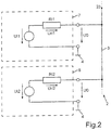
- FIG. 2 shows a circuit diagram of a voltage source and an energy store, according to some embodiments
- FIG. 3 shows characteristic curves for voltages, according to some embodiments
- FIG. 4 shows a diagram in which an instantaneous value of a vehicle electrical system voltage is less than a maximum value, according to some embodiments
- FIG. 5 shows a diagram in which the instantaneous value of the vehicle electrical system voltage is greater than the maximum value, according to some embodiments.
- the described components of the embodiment each represent individual features to be considered independently of one another, which can each also refine the embodiment independently of one another and therefore are also to be considered part of the embodiment individually or in a combination other than that shown. Furthermore, the described embodiment can also be supplemented by further ones of the above-described features of the embodiment.
- FIG. 1 shows a motor vehicle 1 , which can be, for example, an automobile, in particular a passenger automobile.
- the motor vehicle 1 has a vehicle electrical system 2 , in which a vehicle electrical system voltage U is provided, which can be provided, for example, between a positive line 3 of the vehicle electrical system 2 and a ground potential 4 of the motor vehicle 1 .
- the positive line 3 can be formed, for example, by a cable and/or a busbar.
- the ground potential 4 can be formed, for example, by a frame and/or a carrier element of the motor vehicle 1 .
- An electrical supply unit 5 and electrical loads are electrically connected to one another via the electrical system 2 . Only one electrical load 6 of the electrical loads is shown in FIG. 1 .
- the supply unit 5 has a voltage source 7 and an energy store 8 in the example shown.
- the voltage source 7 can be, for example, a lithium-ion battery.
- the energy store 8 can be, for example, a lead accumulator, e.g., a lead-acid battery.
- the voltage source 7 and the energy store 8 are continuously electrically connected to one another via the vehicle electrical system 2 , e.g., continuously or permanently connected in parallel.
- the vehicle electrical system voltage U 0 is generated by the voltage source 7 and the energy store 8 .
- the load 6 can be controlled by a monitoring unit 9 such that the load 6 is started and shut down by the monitoring unit 9 .
- the load 6 can be, for example, an electrical starter for an internal combustion engine (not shown) of the motor vehicle 1 .
- the monitoring unit 9 can be implemented, for example, by an engine control unit.
- a start-stop operation of the motor vehicle 1 by means of the load 6 as a starter can be implemented, for example, by the monitoring unit 9 .
- the load 6 Upon switching on or activation of the load 6 by the monitoring unit 9 , the load 6 consumes or requires a supply current I 0 .
- a voltage value of the vehicle electrical system voltage U 0 results depending on a current strength of the supply current I 0 . The reason is that a part of the electrical voltage generated by the voltage source 7 and the energy store 8 drops in a respective internal resistance Ri 1 , Ri 2 .
- an internal voltage Ui 1 , Ui 2 as is generated by the voltage source 7 or the energy store 8 , drops during a current flow partially by the internal resistance voltage Uri 1 , Uri 2 inside the voltage source 7 and energy store 8 , so that the vehicle electrical system voltage U 0 corresponds to the difference of the internal voltage Ui 1 , Ui 2 and the internal resistance voltage Uri 1 , Uri 2 .
- the vehicle electrical system voltage U 0 has a greater voltage value than in the case in which the supply current I 0 flows with an absolute value greater than 0.
- An instantaneous value Ustart of the vehicle electrical system voltage U 0 can be detected by a voltage measuring unit 10 in a manner known per se in the motor vehicle 1 .
- a control unit 11 can ascertain depending on the instantaneous value Ustart of the vehicle electrical system voltage U 0 whether the sinking of the vehicle electrical system voltage U 0 because of the supply current I 0 can be sufficiently large that further loads will be impaired in the functionality thereof. If this is the case, a blocking signal 12 is thus generated by the control unit 11 , which has the effect in the monitoring unit 9 that the load 6 is not started.
- the monitoring unit 9 therefore represents a vehicle function which is this activated if it is recognized by the control unit 11 that the voltage dip would sink to a final value Uend of the vehicle electrical system voltage U 0 , which is less than a threshold value or minimum voltage value Umin.
- the control unit 11 can predict the voltage dip, e.g., the load 6 does not first have to be activated, but rather the voltage dip is predicted or forecast. For this purpose, the control unit 11 additionally ascertains a current value 13 of the presumably flowing supply current I 0 , as can result upon the start or after the start of the load 6 . For example, the current value 13 can be communicated to the control unit 11 by the monitoring unit 9 .
- the control unit 11 can be implemented, for example, on the basis of a microcontroller or microprocessor.
- FIG. 3 shows, depending on the charge state L of the energy store 8 and a lithium-ion battery as the voltage source 7 , the resulting vehicle electrical system voltage U 0 .
- a generator (not shown) generates a charge voltage Uchar, which can be 15.5 V, for example.
- the voltage source 7 as the lithium-ion battery and the energy store 8 are charged as a result of the charge voltage Uchar.
- a lead accumulator overall itself generates as a result of the overvoltage effect, e.g., without the charge voltage Uchar, in particular at most a terminal voltage or vehicle electrical system voltage which is a maximum value Umax, for example, 13.5 V, which is less than the charge voltage Uchar.
- the energy store 8 If a greater voltage, such as the charge voltage Uchar, is applied at the terminals of the energy store 8 , it thus no longer reacts with a charge current. In the same way, the energy store 8 also does not independently generate a discharge current for the case in which the vehicle electrical system voltage U 0 is in a range between the charge voltage Uchar and the maximum value Umax of the vehicle electrical system voltage. This range is identified in FIG. 3 as the voltage phase SP 1 . If the vehicle electrical system voltage U 0 has a voltage value which is less than or equal to the maximum value Umax, a discharge current also results at the energy store 8 . This voltage situation, in which the energy store 8 also reacts with a discharge current, is identified as the voltage phase SP 2 in FIG. 3 .
- FIG. 4 and FIG. 5 illustrate how the voltage dip 14 to the final value Uend can be prognosticated or forecast by the control unit 11 proceeding from the instantaneous value Ustart of the vehicle electrical system voltage U 0 already before the start of the load 6 on the basis of the current value 13 .
- FIG. 4 illustrates in this case that the voltage phase SP 2 is already provided by the instantaneous value Ustart, e.g., the value Ustart is less than or equal to the maximum value Umax.
- FIG. 4 illustrates two cases for the supply current I 0 . In a first case, the current value 13 for the supply current I 0 has the value I 01 . For a second case, the current value 13 for the supply current I 0 is the current value I 02 , which is greater than the current value I 01 . Since the voltage phase 2 is provided, the control unit 13 presumes that the supply current I 0 is provided both by the voltage source 7 and also the energy store 8 . A partial current 15 , 16 thus results in each case.
- FIG. 5 illustrates the case that the voltage phase SP 1 is signaled by the instantaneous value Ustart of the vehicle electrical system voltage U 0 as the starting situation.
- the instantaneous value Ustart of the vehicle electrical system voltage U 0 is greater than the maximum value Umax.
- the control unit 11 firstly ascertains a source current I 1 , which is exclusively generated by the current source 7 and is sufficiently large that the maximum value Umax would result at the terminals of the voltage source 7 .
- the voltage of the energy store 8 is composed of the internal voltage Ui 2 and in overvoltage (not shown), as is known per se in conjunction with lead accumulators from the prior art.
- a method for the predictive ascertainment of the voltage dip 14 upon current load of the vehicle electrical system 2 by a load 6 with a load current I 0 is thus provided by the control unit 11 . It can be taken into consideration for this purpose that the supply current is provided by multiple electrical stores, namely the voltage source 7 and the energy store 8 . Nonetheless, a correct prediction of the final value Uend of the vehicle electrical system voltage U 0 is possible. Depending on the value Ustart of the vehicle electrical system voltage U 0 applied upon the beginning of the current load in the vehicle electrical system 2 , the voltage dip differs significantly, because two different voltage phases SP 1 , SP 2 can result.
- the control unit 11 differs accordingly between the voltage phases SP 1 , SP 2 for the predictive estimation of the voltage dip 14 .
- the individual current allocation to the voltage source 7 and the energy store 8 is considered depending on the properties of the electrical supply unit 5 used, e.g., the voltage source 7 and the energy store 8 . It is thus ensured that at an arbitrary value Ustart for the vehicle electrical system voltage U 0 , the voltage dip 14 can be correctly ascertained predictively for all possible current values 101 , 102 of the supply current I 0 and for each charge state L.
- the described case differentiation between the voltage phase SP 1 and the voltage phase SP 2 enables the voltage dip 14 to be determined exactly and independently of the starting voltage, as described by the voltage value 9 , and/or the current strength load of the supply current I 0 . A prediction of the voltage dip 14 in the motor vehicle 1 is thus ensured.
- the voltage level of the operating point according to the instantaneous voltage value Ustart upon beginning of the current load according to the supply current I 0 is located below or exactly at the level of the voltage value of the idle voltage including the overvoltage of the energy store 8 , e.g., at the level of or below the maximum value Umax.
- the complete idle voltage curve of the energy store 8 is covered by the voltage source 7 . Therefore, in this case the voltage dip 14 can be computed by a parallel circuit of the store internal resistances Ri 1 , Ri 2 .
- the determination of the voltage dip 14 can be performed in this case both for the voltage at the terminals of the voltage source 7 and also of the energy store 8 , depending on which interconnection topology is presumed.
- the voltage phase SP 1 results as the initial phase or starting phase.
- the voltage dip 14 from the operating point to the maximum value Umax has to be computed separately here.
- the voltage source 7 assumes the complete current value I 1 up to the voltage level of the maximum value Umax here. It then changes into the voltage phase SP 2 .
- the voltage dip 14 is ascertained here from the voltage value or maximum value Umax up to the final voltage value Uend by the allocation of the remaining residual current Id onto the two corresponding to the resistances Ri 1 , Ri 2 thereof.
- the partial currents 15 , 16 result.
- the example shows how a method for ascertaining the voltage dip in a multiple battery vehicle electrical system in conventional motor vehicles can be provided by the embodiment.
Landscapes
- Engineering & Computer Science (AREA)
- Power Engineering (AREA)
- General Physics & Mathematics (AREA)
- Physics & Mathematics (AREA)
- Combustion & Propulsion (AREA)
- Chemical & Material Sciences (AREA)
- Microelectronics & Electronic Packaging (AREA)
- Computer Hardware Design (AREA)
- Sustainable Energy (AREA)
- Mechanical Engineering (AREA)
- Transportation (AREA)
- Life Sciences & Earth Sciences (AREA)
- Sustainable Development (AREA)
- Electric Propulsion And Braking For Vehicles (AREA)
- Charge And Discharge Circuits For Batteries Or The Like (AREA)
Abstract
Description
SP2:Uend=Ustart−I0Rp,
-
- wherein Rp=Ri1∥Ri2 (resistances connected in parallel).
SP1:Uend=Ustart−I01Ri1
SP1+SP2:I1=(Ustart−Umax)/Ri1
SP1+SP2:Id=I0−I1
SP1+SP2:Uend=Umax−Id Rp
Claims (16)
Applications Claiming Priority (4)
| Application Number | Priority Date | Filing Date | Title |
|---|---|---|---|
| DE102015012415 | 2015-09-25 | ||
| DE102015012415.3 | 2015-09-25 | ||
| DE102015012415.3A DE102015012415B4 (en) | 2015-09-25 | 2015-09-25 | Prediction of a voltage drop in a motor vehicle |
| PCT/EP2016/001233 WO2017050404A1 (en) | 2015-09-25 | 2016-07-15 | Prediction of a voltage dip in a motor vehicle |
Publications (2)
| Publication Number | Publication Date |
|---|---|
| US20180275174A1 US20180275174A1 (en) | 2018-09-27 |
| US10670640B2 true US10670640B2 (en) | 2020-06-02 |
Family
ID=56555355
Family Applications (1)
| Application Number | Title | Priority Date | Filing Date |
|---|---|---|---|
| US15/762,718 Active 2036-10-01 US10670640B2 (en) | 2015-09-25 | 2016-07-15 | Prediction of a voltage dip in a motor vehicle |
Country Status (4)
| Country | Link |
|---|---|
| US (1) | US10670640B2 (en) |
| CN (1) | CN108028534B (en) |
| DE (1) | DE102015012415B4 (en) |
| WO (1) | WO2017050404A1 (en) |
Families Citing this family (5)
| Publication number | Priority date | Publication date | Assignee | Title |
|---|---|---|---|---|
| DE102018108101A1 (en) * | 2018-04-05 | 2019-10-10 | Seg Automotive Germany Gmbh | Electronic measuring device for a starter of an internal combustion engine, starter and method for determining a state of an on-board voltage network connected to the starter |
| US11342705B2 (en) * | 2018-04-17 | 2022-05-24 | Aptiv Technologies Limited | Electrical power supply device and method of operating same |
| US11652315B2 (en) | 2018-04-17 | 2023-05-16 | Aptiv Technologies Limited | Electrical power supply device |
| DE102021101600B4 (en) * | 2021-01-26 | 2025-09-04 | Audi Aktiengesellschaft | On-board power system for a motor vehicle, motor vehicle and method for operating an on-board power system |
| CN116061957A (en) * | 2021-10-29 | 2023-05-05 | 上海汽车集团股份有限公司 | Method, device and equipment for predicting failure of redundant power supply system of vehicle |
Citations (14)
| Publication number | Priority date | Publication date | Assignee | Title |
|---|---|---|---|---|
| US6275001B1 (en) * | 1998-09-17 | 2001-08-14 | Volkswagen Ag | Dual-battery system |
| US20010035757A1 (en) * | 2000-03-09 | 2001-11-01 | Rainer Maeckel | Method and apparatus for identification of an external power supply in a motor vehicle |
| US20030042872A1 (en) * | 2001-08-30 | 2003-03-06 | Larson Gerald L. | Vehicle battery charging system |
| DE10232539A1 (en) | 2002-07-18 | 2004-02-05 | Robert Bosch Gmbh | Energy/load management in on-board electrical system involves determining available peak power before load switch-on, delaying switch-on if insufficient power, increasing power and/or reducing load |
| US20100224157A1 (en) | 2009-03-03 | 2010-09-09 | Denso Corporation | Apparatus for detecting the state of battery |
| DE102009001300A1 (en) | 2009-03-03 | 2010-09-09 | Robert Bosch Gmbh | Method and device for determining a characteristic quantity for detecting the stability of the vehicle electrical system |
| US20110001352A1 (en) | 2009-07-01 | 2011-01-06 | Denso Corporation | Power source apparatus for vehicle |
| US20110027626A1 (en) * | 2009-07-31 | 2011-02-03 | Thermo King Corporation | Electrical storage element control system for a vehicle |
| DE102011014811A1 (en) | 2011-03-23 | 2011-10-06 | Daimler Ag | Bus e.g. electric bus, has electrical energy storage comprising energy battery, where energy battery including higher power density and lower energy density than that of power battery |
| DE102011054582A1 (en) | 2010-10-19 | 2012-04-19 | Denso Corporation | Device for controlling battery system of vehicle, has variable adjustment unit for adjusting target charging amount based on state variable that stands in relation with regenerative charging condition and/or unloading state of battery |
| EP2469070A1 (en) | 2010-12-21 | 2012-06-27 | Eberspächer Controls GmbH & Co. KG | Limitation of the drop in starting voltage in the electrical system of a motor vehicle |
| US20130158776A1 (en) * | 2011-12-14 | 2013-06-20 | Guy T. Rini | Electrical system health monitor (eshm) system and method |
| DE102012217184A1 (en) | 2012-09-24 | 2014-06-12 | Bayerische Motoren Werke Aktiengesellschaft | Energy management for motor vehicle with coupling storage device |
| US20170106758A1 (en) * | 2013-07-31 | 2017-04-20 | Sanyo Electric Co., Ltd. | Power source system for a vehicle |
Family Cites Families (7)
| Publication number | Priority date | Publication date | Assignee | Title |
|---|---|---|---|---|
| NZ229179A (en) * | 1989-05-17 | 1992-09-25 | Pita Witehira | Dual battery power distribution system for cars |
| JP4572840B2 (en) * | 2006-02-10 | 2010-11-04 | 株式会社明電舎 | DC power storage device |
| US7840969B2 (en) * | 2006-04-28 | 2010-11-23 | Netapp, Inc. | System and method for management of jobs in a cluster environment |
| JP4201050B2 (en) * | 2006-10-11 | 2008-12-24 | トヨタ自動車株式会社 | Electric load control device, electric load control method, electric load control device, and electric load control method |
| FR2983435B1 (en) * | 2011-12-05 | 2014-01-24 | Peugeot Citroen Automobiles Sa | METHOD FOR MANAGING THE ELECTRIC ENERGY OF A MOTOR VEHICLE AND MOTOR VEHICLE USING SUCH A METHOD |
| US9556860B2 (en) * | 2012-04-27 | 2017-01-31 | Medtronic, Inc. | Implantable infusion device having selective voltage boost circuit with charge pump circuit for generating control signals using first and second profiles |
| CN204205591U (en) * | 2014-12-11 | 2015-03-11 | 三峡大学 | A kind of electric automobile can the high reliability DC distribution net of flexible access |
-
2015
- 2015-09-25 DE DE102015012415.3A patent/DE102015012415B4/en active Active
-
2016
- 2016-07-15 US US15/762,718 patent/US10670640B2/en active Active
- 2016-07-15 CN CN201680055594.3A patent/CN108028534B/en active Active
- 2016-07-15 WO PCT/EP2016/001233 patent/WO2017050404A1/en not_active Ceased
Patent Citations (15)
| Publication number | Priority date | Publication date | Assignee | Title |
|---|---|---|---|---|
| US6275001B1 (en) * | 1998-09-17 | 2001-08-14 | Volkswagen Ag | Dual-battery system |
| US20010035757A1 (en) * | 2000-03-09 | 2001-11-01 | Rainer Maeckel | Method and apparatus for identification of an external power supply in a motor vehicle |
| US20030042872A1 (en) * | 2001-08-30 | 2003-03-06 | Larson Gerald L. | Vehicle battery charging system |
| DE10232539A1 (en) | 2002-07-18 | 2004-02-05 | Robert Bosch Gmbh | Energy/load management in on-board electrical system involves determining available peak power before load switch-on, delaying switch-on if insufficient power, increasing power and/or reducing load |
| US20100224157A1 (en) | 2009-03-03 | 2010-09-09 | Denso Corporation | Apparatus for detecting the state of battery |
| DE102009001300A1 (en) | 2009-03-03 | 2010-09-09 | Robert Bosch Gmbh | Method and device for determining a characteristic quantity for detecting the stability of the vehicle electrical system |
| US20110001352A1 (en) | 2009-07-01 | 2011-01-06 | Denso Corporation | Power source apparatus for vehicle |
| US20110027626A1 (en) * | 2009-07-31 | 2011-02-03 | Thermo King Corporation | Electrical storage element control system for a vehicle |
| DE102011054582A1 (en) | 2010-10-19 | 2012-04-19 | Denso Corporation | Device for controlling battery system of vehicle, has variable adjustment unit for adjusting target charging amount based on state variable that stands in relation with regenerative charging condition and/or unloading state of battery |
| EP2469070A1 (en) | 2010-12-21 | 2012-06-27 | Eberspächer Controls GmbH & Co. KG | Limitation of the drop in starting voltage in the electrical system of a motor vehicle |
| DE102011014811A1 (en) | 2011-03-23 | 2011-10-06 | Daimler Ag | Bus e.g. electric bus, has electrical energy storage comprising energy battery, where energy battery including higher power density and lower energy density than that of power battery |
| US20130158776A1 (en) * | 2011-12-14 | 2013-06-20 | Guy T. Rini | Electrical system health monitor (eshm) system and method |
| DE102012217184A1 (en) | 2012-09-24 | 2014-06-12 | Bayerische Motoren Werke Aktiengesellschaft | Energy management for motor vehicle with coupling storage device |
| US20150191100A1 (en) | 2012-09-24 | 2015-07-09 | Bayerische Motoren Werke Aktiengesellschaft | Energy Management for a Motor Vehicle Having Coupled Energy Storage Devices |
| US20170106758A1 (en) * | 2013-07-31 | 2017-04-20 | Sanyo Electric Co., Ltd. | Power source system for a vehicle |
Non-Patent Citations (7)
| Title |
|---|
| English-language abstract of European Patent Application Publication No. EP 2469070 A1, published Jun. 27, 2012; 1 page. |
| English-language abstract of German Patent Application Publication No. DE 102009001300 A1, published Sep. 9, 2010; 2 pages. |
| English-language abstract of German Patent Application Publication No. DE 102011014811 A1, published Oct. 6, 2011; 1 page. |
| English-language abstract of German Patent Application Publication No. DE 102011054582 A1, published Apr. 19, 2012; 1 page. |
| English-language abstract of German Patent Application Publication No. DE 10232539 A1, published Feb. 5, 2004; 1 page. |
| International Preliminary Report on Patentability directed to related International Patent Application No. PCT/EP2016/001233, dated Apr. 5, 2018; 9 pages. |
| International Search Report and Written Opinion of the International Searching Authority directed to related International Patent Application No. PCT/EP2016/001233, dated Oct. 17, 2016, with attached English-language translation; 20 pages. |
Also Published As
| Publication number | Publication date |
|---|---|
| CN108028534B (en) | 2021-07-06 |
| WO2017050404A1 (en) | 2017-03-30 |
| DE102015012415A1 (en) | 2017-03-30 |
| DE102015012415B4 (en) | 2021-06-10 |
| CN108028534A (en) | 2018-05-11 |
| US20180275174A1 (en) | 2018-09-27 |
Similar Documents
| Publication | Publication Date | Title |
|---|---|---|
| US10670640B2 (en) | Prediction of a voltage dip in a motor vehicle | |
| US20150336523A1 (en) | Vehicle power supply apparatus and vehicle power regeneration system | |
| CN104737412B (en) | Power-supply management system and method for managing power supply | |
| KR20160114133A (en) | Electrical system and method for operating an electrical system | |
| CN109906169B (en) | Operating method for a dual-voltage battery | |
| CN103635347A (en) | Vehicle power source device | |
| KR20070121609A (en) | 2 power vehicle power supply | |
| CN108604812A (en) | Battery balancing apparatus and method | |
| CN105743161B (en) | Supply unit | |
| CN107963040B (en) | Battery pack device, operating method for battery pack device, and vehicle | |
| CN107078535A (en) | Multi-accumulator system for the on-board electrical network of motor vehicles | |
| KR101841559B1 (en) | Method for operation of an onboard power supply | |
| JP2014225942A (en) | Power storage system | |
| US20180292462A1 (en) | State of charge calculation apparatus for secondary battery and storage battery system | |
| US11673485B2 (en) | Method for controlling an electrical system of an electrically drivable motor vehicle having a plurality of batteries, and electrical system of an electrically drivable motor vehicle having a plurality of batteries | |
| US20210261018A1 (en) | Vehicle power supply device | |
| JP2015009654A (en) | Power storage system | |
| CN105383421B (en) | Supply unit | |
| KR20160006443A (en) | Battery System and Method for Operating Internal Resistance | |
| WO2014068864A1 (en) | Vehicle-mounted power storage system | |
| WO2018012302A1 (en) | Power supply device | |
| EP2290388A2 (en) | Battery condition determination | |
| JP2016213969A (en) | Power supply device | |
| JP6409635B2 (en) | Power storage system | |
| JP2015012685A (en) | Power storage system |
Legal Events
| Date | Code | Title | Description |
|---|---|---|---|
| FEPP | Fee payment procedure |
Free format text: ENTITY STATUS SET TO UNDISCOUNTED (ORIGINAL EVENT CODE: BIG.); ENTITY STATUS OF PATENT OWNER: LARGE ENTITY |
|
| AS | Assignment |
Owner name: AUDI AG, GERMANY Free format text: ASSIGNMENT OF ASSIGNORS INTEREST;ASSIGNORS:RENNER, DANIEL;HACKNER, THOMAS;SIGNING DATES FROM 20180326 TO 20180327;REEL/FRAME:046600/0507 |
|
| STPP | Information on status: patent application and granting procedure in general |
Free format text: DOCKETED NEW CASE - READY FOR EXAMINATION |
|
| STPP | Information on status: patent application and granting procedure in general |
Free format text: NON FINAL ACTION MAILED |
|
| STPP | Information on status: patent application and granting procedure in general |
Free format text: RESPONSE TO NON-FINAL OFFICE ACTION ENTERED AND FORWARDED TO EXAMINER |
|
| STPP | Information on status: patent application and granting procedure in general |
Free format text: NOTICE OF ALLOWANCE MAILED -- APPLICATION RECEIVED IN OFFICE OF PUBLICATIONS |
|
| STPP | Information on status: patent application and granting procedure in general |
Free format text: PUBLICATIONS -- ISSUE FEE PAYMENT VERIFIED |
|
| STCF | Information on status: patent grant |
Free format text: PATENTED CASE |
|
| CC | Certificate of correction | ||
| MAFP | Maintenance fee payment |
Free format text: PAYMENT OF MAINTENANCE FEE, 4TH YEAR, LARGE ENTITY (ORIGINAL EVENT CODE: M1551); ENTITY STATUS OF PATENT OWNER: LARGE ENTITY Year of fee payment: 4 |